HAL Id: hal-00510560
https://hal-mines-paristech.archives-ouvertes.fr/hal-00510560
Submitted on 4 Apr 2011HAL is a multi-disciplinary open access
archive for the deposit and dissemination of sci-entific research documents, whether they are pub-lished or not. The documents may come from teaching and research institutions in France or abroad, or from public or private research centers.
L’archive ouverte pluridisciplinaire HAL, est destinée au dépôt et à la diffusion de documents scientifiques de niveau recherche, publiés ou non, émanant des établissements d’enseignement et de recherche français ou étrangers, des laboratoires publics ou privés.
3D FEM simulation of the flow forming process using
Lagrangian and ALE methods
Marie Houillon, Elisabeth Massoni, Eric Ramel, Roland E. Logé
To cite this version:
Marie Houillon, Elisabeth Massoni, Eric Ramel, Roland E. Logé. 3D FEM simulation of the flow forming process using Lagrangian and ALE methods. Materials Processing and Design, Modeling, Simulation and Applications, NUMIFORM ’07: 9th International Conference on Numerical Methods in Industrial Forming Processes, Jun 2007, Porto, Portugal. pp.Pages 257-262, �10.1063/1.2740821�. �hal-00510560�
3D FEM Simulation of the Flow Forming Process Using
Lagrangian and ALE Methods
Marie Houillon*, Elisabeth Massoni*, Eric Ramel**, Roland Loge*
CEMEF, Ecole Nationale Superieure des Mines de Paris, 2 Rue Claude Daunesse, 06904 Sophia Antipolis
marie. houillon(a),ensmp.fr
CEA Valduc, 21120 Is-sur-Tille
Abstract. The process of flow forming is numerically modeled using finite element codes based on the Forge2005®
software. Two numerical approaches are considered. The first one uses an updated Lagrangian formulation. The problem is solved with help of a self-contact management algorithm. The second approach consists in using an ALE formulation that permits to optimize meshing with an adaptive method based on the Zienkiewicz-Zhu error estimation. The ALE method is well adapted to incremental forming processes such as flow forming and allows dealing with difficulties generated by the contact between the work piece and tools. Both formulations are coupled with complex tool kinematics. The Lagrangian formulation gives realistic results. The ALE formulation is promising with regard to computational time, and simulations on simple configurations show fairly good agreements with Lagrangian results.
Keywords: flow forming, finite element method, self-contact, ALE, error estimate, adaptivity.
INTRODUCTION
This paper introduces works and results concerning numerical simulations of the flow forming process. The process is briefly introduced and two numerical approaches are reported. The first uses a Lagrangian formulation and is considered as a reference calculation. Our goal is to obtain results similar to those obtained with the lagrangian formulation but using an ALE formulation with the aim to decrease the computational time. In this paper, preliminary results are reported.
THE FLOW FORMING PROCESS
The flow forming process is a chipless incremental process. It consists in applying a force on a side of a rotating tubular part by means of rollers in such a way that the material is moved along the tube wall in the axial direction (see figure 1). As a result, the tube wall is thinned and elongated. The tube is fixed on a rotating mandrel. The first numerical requirement that must be satisfied to reach a reliable model is the management of material buildup that appears in front of the rollers. This phenomenon may appear in case of large wall reduction rates. This buildup may be stuck again to the workpiece wall due to rollers action. Thus, modelling may take into account self-contact, that is, contact of the tube with itself.
HuCtloc* Backward Spinning
Wortpiaca
3--—
FIGURE 1. Forward and backward flow forming
[10]
The second and main difficulty in modelling flow forming or single point incremental forming is underlined by Jeswiet [11]: the zone of contact between tool and workpiece is much localised, it has a complex geometry, generates locally very important thermomechanical gradients and sweeps most of the surface of the part. Indeed, the zone of contact between a roller and the part covers not more than 0.05% of the surface of the part which will be worked, i.e. the surface potentially in contact with the roller until completion of the flow forming pass.
An accurate modelling of the local material deformation is deeply required so that the cumulated numerical error is acceptable, after several runs of the
tool on the same zone. A fine grid is required on such zone and coarse grid on the remainder of the part. The grid is to be frequently refined and coarsened because this zone is constantly moving. Variables remap that occurs after refinement or coarsening must be efficient since it can generate a loss or a diffusion of information.
THE FINITE ELEMENT MODEL
Two codes have been tested to model the flow forming process. The first one uses an updated Lagrangian formulation supported by the commercial software Forge2005® upgraded with an algorithm that deals with self-contact. The second one uses an ALE formulation.
The Lagrangian Formulation
The Forge2005® code uses an implicit method with a mixed standard Galerkin P1+/P1 velocity/pressure formulation. The mechanical problem is solved on a given increment knowing the previous one. The problem is written in a compact form as follows:
R(X'+A',V'+A',P'+A') = O (l)
where X'+Al, V'+Al and P'+At are respectively the
material coordinates, the velocity and the pressure at increment t + At.
The equation (1) is solved iteratively.
To model the material buildup (as mentioned in the flow forming description), we use an enhanced version of the code that contains an algorithm dealing with self-contact.
This algorithm has been developed by Barboza [1,2,6]. It consists in a two-stage fold detection.
The first stage consists in a geometrical approach. For each centre of mass P of a surface element F of the part, the intersection of the ray intercepted by P and perpendicular to F with other facets belonging to the surface of this same object is investigated as shown on the figure 2. The result of this research gives a set of elements named F'. For instance, on the sketch of figure 2, F' consists of two elements, F'i and F'2.
The second stage consists in submitting this set of elements to another test that consists in calculating the scalar product of both normal vectors of each couple of elements F/F'. If this product is lower than -1/2, then the angle formed by these two normal vectors lies between 120° and 240° and both elements F/F' are potentially in contact. On the sketch of figure 2, the element F'i is still considered as in a potential
situation of self-contact with the element F, whereas the element F'2 is not any more after the second test.
Once surfaces potentially in situation of self-contact are defined, they are dealt with a particular treatment based on an algorithm handling contact between different deformable bodies and that has been adapted to this particular situation, i.e., contact between two surfaces of the same body [1].
FIGURE 2. Determination of potential folds [1]
The ALE Formulation
Mesh management is a complicate issue in modelling metal forming processes involving large deformation such as flow forming, especially with a Lagrangian method. The same initial finite element mesh cannot be used through the whole process. Remeshing must be frequently carried out in order to avoid elements distortion. However, the remeshing stage is time consuming and may result in numerical errors due to variables remap from old to new grid. The ALE method (Arbitrary Lagrangian Eulerian) allows a compromise between the lagrangian formulation that tends to degenerate meshes and the Eulerian formulation that does not allow any mesh motion. Possible movements of the grid relatively to the material limit mesh distortion without any catastrophic increase of computational time.
The Forge2005® ALE code [4] uses the uncoupled ALE method. It consists in solving the problem with a updated Lagrangian formulation and then proceeding to a regularization of the grid which ideally tends to preserve the optimal shapes of elements, keeping nodes connectivity unchanged. The velocity of the grid is derived from specific criteria that are suited to each particular problem. This grid velocity can be zero, equal or different from the velocity of the material. An error estimate is used in order to determine the optimal size of the elements of the mesh and indirectly the velocity of the grid [7,8,9].
The ALE formulation adds to the Lagrangian form the following problem written in the compact form:
D(X'+A',V'+A',W'+A') = 0 (2)
where WnAl is the grid velocity.
Free Surfaces
With the aim of obeying free surfaces conditions, the normal component of the velocity of the surface grid is set equal to the material normal velocity. The problem is complex when it comes to preserve volume and respect the complex geometries of free surfaces at regularization stage. In flow forming, locally deforming surfaces, in contact with the tools, may adopt a complex geometry. A fine grid and a good management of the movement of the surface mesh are necessary. The algorithm used to manage the free surfaces in this code makes it possible to take into account the edges and vertices of the free surface [8,9].
Mesh Adaptation With Error Estimate
An R-adaptation is used in the ALE formulation. It consists in improving the solution by optimization of the position of the nodes without addition of new ones or modification of connectivities. The number of degrees of freedom does not vary from one increment to the next one.
The technique of adaptation implemented in the Forge2005® ALE code was initially developed by Boussetta [3]. It consists in defining an optimized element size map based on the Zienkiewicz-Zhu error estimator [12]. This map is used to carry out an adaptive remeshing. In the ALE code, the same algorithm is used to define the optimal size of the elements and indirectly the velocity of the grid. Adaptive remeshing remains possible however.
Optimization Strategy
A strategy of optimization based on user-imposed
precision is used. This strategy established by Coffignal [5] and Zienkiewicz [12] induces a reduction of the total whole domain error and an error homogenization on all the elements of the domain. The size variation of an element during a remeshing is derived according to the error evaluated on the considered element and the total error tolerated on the domain. The size variation ratio is used as a coefficient
Ce introduced into a geometrical centering carried out
on each node.
x=wr\HCexge n\ eeT„
(3)
where r is the close vicinity of the e element and
x is the centre of the facet of the e element.
The coefficient Ce contains also an adaptation
criterion and a volume quality criterion in order to
moderate elements distortion subjected to the adaptation criterion. The grid velocity is easily obtained from the Lagrangian coordinates and the grid coordinates.
Zienkiewicz-Zhu Error Estimator
The Zienkiewicz and Zhu error estimator (Z2) [12] is based on the computation of a solution closer to the exact solution than the finite element one. This a posteriori derived solution exhibits a higher order compared to the finite element solution. The Z2 error is the difference between this solution and the finite element solution. The solution is expressed as a power norm as follows:
s : \£-£uco )dt 1/2
(4)
This solution is built by using an interpolation of nodally recovered values, namely the SPR technique (Superconvergent Patch Recovery) [3].
NUMERICAL COMPUTATIONS
FIGURE 3 Flow forming including a mandrel, a roller and a closed tube configuration.
The flow forming configuration is shown in figure 3. It is made up of a closed tube, a mandrel and several rollers uniformly distributed around the rotation axis (see figure 3).
Contrary to the real process where the flow formed part is in rotation and translation, the tube is fixed in the FEM model. Therefore, rollers are set in motion as floating dies. Their motion is a combination of a translation along the part axis, a rotation around their own axis and a rotation of rollers axis around the part axis. Translation and the latter rotation velocities are known a priori. But the former roller revolution velocity is considered as unknown and derived from the FEM calculation.
The same configuration is used for testing both numerical codes, Lagrangian and ALE.
RESULTS
Lagrangian Formulation
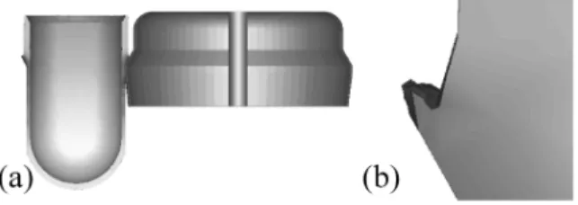
In comparison with simulation without management of the self-contact, we achieved the completion of a flow forming pass. Folds and self-contacts are well behaved (See figure 4). This calculation took more than 30 days with a processor P4 3.20 GHz.
FIGURE 4 (a) Flow forming simulation with self-contact management (b) Zoom on the fold
ALE Formulation
Figure 5 (a) and (b) shows contact zones between workpiece and rollers when using an ALE formulation. The mesh is refined in high strain rate gradients zones.
FIGURE 5 (a) Tube meshing in case of using several
rollers, (b) Optimization of the size of the elements in contact with rollers.
In the ALE method, the elements size is currently only controlled by the Z2 error estimator. It can be noted that the grid is actually refined on the elements exhibiting, at the same time, strong gradients of Von Mises stresses and strain rates.
Nevertheless, apart from the zones exhibiting strong gradients of power, the Z2 error estimator authorizes an increase of the elements size. For instance, the furrow created by the tool, whose geometry is complex, does not exhibit a strong gradient of power after the tool has passed. The elements are coarsened and this complex geometry is not respected. Enforcing a proper elements size on
those kinds of surface will be a first improvement to the regularization algorithm occurring in the ALE formulation.
Comparison Between Lagrangian And
ALE Formulation
The figure 6 shows roller/workpiece contact for a plane flow forming configuration, i.e. a roller rolling on a sheet, computed with three different numerical configurations.
We study this plane configuration so that we can focus on the contact zone and this configuration is not as time consuming as a real flow forming configuration.
The first column shows mesh, contact with roller zone, Von Mises stresses, strain rate, and cumulated strain using a Lagrangian formulation without remeshing. The mesh is fine before calculation on the roller path. This requires a high number of elements, which cannot be conceivable in flow forming simulation because of the extent of the roller path. The second column gives the same data with the same code but authorising remeshings. In that case, mesh size is optimized by means of remeshings at each increment. The remeshing procedure is computationally expensive. The third one shows the same data obtained with an ALE formulation that optimizes elements size by means of mesh regularization.
In comparison with the Lagrangian method, the ALE method results in a computational time reduction connected either to a lower number of elements or to a lower number of remeshings.
For instance, between Lagrangian formulation with remeshings and ALE formulation, the numbers of elements are quite similar, but computational time is 2 times superior using the Lagrangian formulation because of the remeshings occurring at each increment. The stage of grid regularization added to the calculation at each increment in the ALE formulation is far less time consuming than the remeshing.
This ALE adaptation, in the same way as with remeshings, can generate strong gradients of elements size which results in information diffusion as it can be seen on the last row of figure 6. These three pictures show the cumulated strain. The diffusion of the strain occurs with use of remeshing and regularization. This diffusion is due to the variables remap that follows the regularization step or remeshing. It can be noted that the diffusion occurs mainly on the zone that underwent elements coarsening in case where the ALE formulation is used.
Finally, figure 6 (d) and (e) show that the mesh, optimized with an error estimator in the ALE
formulation, is refined so that good instantaneous results are obtained, i.e. Von Mises stresses and strain rates. Those results are pretty close to those obtained
with the "reference" model, i.e., the lagrangian method without remeshing.
Lagrangian formulation without remeshing
Lagrangian formulation with
remeshings ALE formulation
(a) (b) (c) (d) (e)
»
'MS& WM
If
425 403 380 358 335 313 290 268 245 223 200 5 - 4 _ 3 _2 1 - 0J
425 403 380 358 335 313 290 268 245 223 200 5 4 3 _2 1 - o ** V
425 403 380 358 335 313 290 268 245 223 200 1 10.9 0.8 0.7 0.6 0.5i Jo. 4 _0.3 0.2 ~0.1 - 0CONCLUSION
The lagrangian formulation shows good results for flow forming simulation providing folds are being handled properly.
With regard to tool kinematics, contact zones, and deformation localizations, using an ALE formulation to model flow forming is well justified by the incremental nature of this metal forming process. The Z2 estimator permits to impose a fine grid on contact
zones between the roller and the part i.e. on the zones of the part where the instantaneous strain is the largest. On the other hand, the code does not allow a sufficiently fine grid on those surfaces having a complex geometry and where the estimator of Z2 does
not impose refinement.
The aim of our work is to reach the same mechanical fields with the ALE formulation as with the Lagrangian one without remeshings, but lowering significantly the computational time.
The diffusion of information, occurring in case of remeshings for the Lagrangian method, and in case of mesh coarsening for the ALE method, is a problem that must still be solved.
In the future, improvements in variables remap accuracy and free surfaces conservation must still be carried out in the ALE formulation.
Complex geometries will be taken into account in the calculation of the elements size map with a geometrical error estimator.
REFERENCES
1. Barboza, J., "Traitement du contact entre corps deformables et calcul parallele pour la simulation 3D du forgeage multicorps", Ph.D. Thesis, Ecole des Mines de Paris, 2004
2. Barboza J. & Fourment L. "3D contact problem between deformable bodies in forging: parallel and algorithmic aspects", VII International Conference on Computational Plasticity, COMPLAS, Barcelona, April 7-10, 2003 3. Boussetta R., "Estimateurs d'erreur et remaillage
adaptatif: application a la simulation 3D des precedes de mise en forme des materiaux", Ph.D. Thesis, Ecole des Mines de Paris, 2005
4. Chenot J-L., Bellet M., "The ALE method for the numerical simulation of material forming processes",
Simulation of Materials Processing: Theory, Methods and Applications, 1995, p. 39-48.
5. Coffignal G., Optimisation et fiabilite des calculs elements finis en elastoplasticite, Ph.D. Thesis, Universite Pierre et Marie Curie, 1987
6. Fourment L., Barboza J., Popa S. "Master / slave algorithm for contact between deformable bodies and axial symmetries - Application to 3D metal forging", Second M.I.T. Conference on Computational Fluid and Solid, Cambridge, June 17-20 2003
7. Fourment L., Delalondre F., Guerdoux S., "Simulation Numerique 3D de la formation de Bandes de Cisaillement Adiabatique aux Grandes Vitesses", Colloque HSIMP, Senlis, 2007
8. Fourment L., Guerdoux S., "Enhanced transport and remeshing schemes for ALE formulation applied to Friction Stir Welding", Proceedings of the 9th Esaform Conference on Material Forming, Glasgow, United Kingdom, p. 75-78, April 26-28, 2006, edited by N. Juster and A. Rosochowsky, Akapit, Krakow, Poland 9. Guerdoux S., Fourment L., "Error estimation and
accurate mapping based ALE formulation for 3D simulation of Friction Stir Welding", Numiform 2007, Porto, 1 7 - 2 1 June 2007
10. Gur M., Tirosh J., "Plastic flow instability under compressive loading during shear spinning process", Transactions of the ASME, Journal of Engineering for
Industry, Vol 104, 1982, p. 17-22
11. Jeswiet J., Micari F., Hirt G., Bramley A., Duflou J., Allwood J., "Asymmetric Single Point Incremental Forming of Sheet Metal", 55th general assembly of
CIRP, Antalya, Turkey, Keynotes papers, vol. 54, n°2, 2005, p. 623-649.
12. Zienkiewicz O.C., Zhu J.Z., "A simple error estimator and adaptive procedure for practical engineering analysis", International Journal for Numerical Methods
![FIGURE 1. Forward and backward flow forming [10]](https://thumb-eu.123doks.com/thumbv2/123doknet/12996509.379707/2.918.490.805.505.704/figure-forward-backward-flow-forming.webp)
![FIGURE 2. Determination of potential folds [1]](https://thumb-eu.123doks.com/thumbv2/123doknet/12996509.379707/3.918.507.792.226.362/figure-determination-of-potential-folds.webp)