Cathodic Electrodeposition of Metal-Organic Frameworks by Minyuan Miller Li B.S., University of Iowa (2010)
AMM"VE
MASSACHIDSETTS INSTITUTE OF TECHNOLOGYNOV 0
9
2015
LIBRARIES
Submitted to the Department of Chemistryin Partial Fulfillment of the Requirements for the Degree of
Doctor of Philosophy
at the
MASSACHUSETTS INSTITUTE OF TECHNOLOGY
September 2015
2015 Massachusetts Institute of Technology. All rights reserved
Signature of
Author-Signature redacted
Department of Chemistry August 7, 2015Signature redacted
Certified by... .... .... . ...Sig
Accepted by Mircea Dinca Associate Professor of Chemistry Thesis Supervisornature redacted
.... ....
.... .... .... ...
Robert W. Field Haslam and Dewey Professor of Chemistry Chairman, Departmental Committee on Graduate StudentsThis doctoral thesis has been examined by a Committee of the Department of Chemistry as follows:
Signature redacted
Stephen J. Lippard Arthur Amos Noyes Professor of Chemistry Committee ChairmanSignature redacted
Mircea Dincd Associate Professor of Chemistry Thesis SupervisorSignature redacted
Yogesh SurendranathAssistant Professor of Chemistry
Cathodic Electrodeposition of Metal-Organic Frameworks
by
Minyuan Miller Li
Submitted to the Department of Chemistry on August 7h, 2015 in Partial Fulfillment of the Requirements for the
Degree of Doctor of Philosophy in Chemistry
ABSTRACT
Metal-organic frameworks (MOFs) represent a class of functional coordination polymers with long-range order, great synthetic flexibility, and exceptionally high internal surface area. Although they have been proposed for a myriad of potential applications, many of these require that MOFs be processed as thin films or other nanostructures to reach peak performance. Thus, a general and facile fabrication process is still much desired.
In this thesis, I describe cathodic electrodeposition as an alternative approach to MOF crystallization, which is traditionally achieved solvothermally via ligand deprotonation through in-situ formation of base (often by amine release from the decomposition of an amide solvent). In cathodic electrodeposition, electrochemical reduction of probase molecules produces base equivalents to initiate the metal-ligand bond formation and subsequently the self-assembly process. There are three major advantages to this process in the context of producing MOF films: 1) the formation of base can be controlled more precisely, 2) the acid-base reaction is spatially confined close to the electrode surface, and 3) electrodeposition is, by definition, conformal, and therefore lends itself to electrodes of any geometry, as will be shown in Appendix I. Using cathodic electrodeposition, several Zn-BDC (BDC: 1,4-benzenedicarboxylate) MOFs could be formed as polycrystalline coatings on electrodes. In particular, a microporous composite of Zn40(BDC)3,
i.e. MOF-5, and Zn metal could be synthesized at room temperature in less than 15 minutes. This work is described in Chapter 2. By modulating the pH at the electrode surface in the presence of an appropriate probase, biphasic or bilayer structures of different polymorphs could also be accessed with a simple change in the applied potential, thereby providing a facile means of making composite films described in Chapter 4. Lastly, systematic studies of the effects of various variables on the electrodeposition process brought unique mechanistic insights to the early stages of MOF crystallization, as described in Chapter 3. Chapters 1 and 5 provide a context for this research within the larger area of MOF film formation, and a preliminary account on the possible sources of the p4-02- atom in the iconic MOF-5 structure, respectively.
Thesis Supervisor: Mircea Dinca Title: Associate Professor of Chemistry
Table of Contents
ABSTRACT ... 5
Chapter 1. Electrochemistry in Metal-Organic Frameworks: Progress towards Thin-Film Devices ... 13
1.1 Abstract ... 13
1.2 Metal-Organic Frameworks for Electrochemical Applications: Promises and Progress... 13
1.3 M OFs, Electrodes, and Thin Film s ... 14
1.3.1 The M OF-Electrode Interface ... 15
1.3.2 M OF Thin Films ... 17
1.3.3 Electrochemical Fabrication of M OF Thin Films ... 18
1.4 References...20
Chapter 2. Cathodic Electrodeposition: Fabrication and Characterization of MOF-5/Zn Composites on Fluorine-doped Tin Oxide Electrodes... 25
2.1 Abstract ... 25
2.2 Introduction...25
2.3 Results and Discussion ... 27
2.4 Conclusion ... 37
2.5 Experim ental M ethods ... 38
2.6 References...41
Chapter 3. Mechanisms and Transformations: the Impact of Experimental Conditions on the MOF-5/Zn Com posites Synthesized on FTO Electrodes ... 45
3.1 Abstract ... 45
3.2 Introduction...45
3.3 Results and D iscussion ... 46
3.4 Conclusion ... 51
3.5 Experim ental M ethods ... 52
3.6 References...55
Chapter 4. Selectivity through Potential Bias: the Formation of Biphasic and Bilayer MOF Thin Films on Platinum Electrodes ... 57
4.1 Abstract ... 57
4.2 Introduction... 57
4.3 Results and Discussion ... 59
4.4 Conclusion ... 65
4.5 Experim ental M ethods ... 66
4.6 References...68
Chapter 5. The Origin of p4-Oxo in MOF-5 under Cathodic Electrodeposition: Metal Electrode Surface Reactivity and a Probase System w ith 02...71
5.1 Abstract...71
5.2 Introduction...71
5.3 Results and Discussion ... 73
5.4 Conclusion ... 79
5.5 Experimental M ethods ... 80
5.6 References...83
Appendix I. Substrate-Mounted MOF-5 Membranes for Gas Separation: Prototype Development and Performance Evaluation...86
Appendix II. Supplemental Information to Chapter 2--Cathodic Electrodeposition: Fabrication and Characterization of MOF-5/Zn Composites on Fluorine-doped Tin Oxide Electrodes... 99
Appendix III. Supplemental Information to Chapter 3-Mechanisms and Transformations: the Impact of Experimental Conditions on the MOF-5/Zn Composites Synthesized on FTO Electrodes... 118
Appendix IV. Supplemental Information to Chapter 4-Selectivity through Potential Bias: the Formation of Biphasic and Bilayer M OF Thin Films on Platinum Electrodes ... 131
Appendix V. Supplemental Information to Chapter 5-Mechanisms and Transformations: The Origin of p4-Oxo under Cathodic Electrodeposition: Metal Electrode Surface Reactivity and a Probase System with 0 2 ... 16 3 ACKNOW LEDGEM ENTS ... 190
List of Figures
Figure 2.1. Cyclic voltammograms of NaNO3, ZnCl2, and H2BDC on FTO...28
Figure 2.2. Cyclic voltammogram of a MOF-5 deposition bath and the corresponding bulk electrolysis chronoam perogram ... 29
Figure 2.3. PXRD pattern of a MOF-5/Zn composite thin film deposited on FTO...30
Figure. 2.4. XPS survey scan of a MOF-5/Zn thin film deposited on FTO... 31
Figure 2.5. XPS regional scans on C, Cl, 0, and Zn... 32
Figure 2.6. N2 adsorption isotherm for a MOF-5/Zn thin film deposited on FTO... 33
Figure 2.7. 'H NMR spectrum of an acid-digested MOF-5/Zn thin film... 34
Figure 2.8. Surface SEM images of a MOF-5/Zn thin flim...35
Figure 2.9. Cross section SEM images of a MOF-5/Zn thin film...36
Figure 3.1. PXRD patterns of MOF-5 samples that were deposited with varied hydration ... 47
Figure 3.2. PXRD patterns of MOF-5 samples that were deposited with varied zinc precursors ... 48
Figure 3.3. Proposed transformation sequence during MOF-5 electrodeposition ... 50
Figure 3.4. PXRD patterns of MOF-5 samples that were specially handled post electrolysis ... 51
Figure 4.1. Cyclic voltammograms of a dilute solution of Et3NHCl and a dilute solution of Et3NHCl and H 2B D C ... 6 0 Figure 4.2. PXRD patterns of (Et3NH)2Zn3(BDC)4 films deposited on Pt gauze electrodes ... 60
Figure 4.3. SEM image and crystal structure of (Et3NH)2Zn3(BDC)4 ... . .. . . .. . . . .. . . . .. . . ..61
Figure 4.4. PXRD patterns of (Et3NH)2Zn3(BDC)4 films deposited, varied durations ... 62
Figure 4.5. PXRD patterns of (Et3NH)2Zn3(BDC)4 films deposited, varied potentials ... 63
Figure 4.6. SEM images of (Et3NH)2Zn3(BDC)4 films deposited, varied potentials ... 63
Figure 4.7. PXRD patterns of (Et3NH)2Zn3(BDC)4 films during a bilayer deposition sequence...65
Figure 4.8. SEM im ages of a bilayer deposition...65
Figure 5.1. The basic zinc carboxylate cluster, Zn40(O2C-)6, of MOF-5 ... 72
Figure 5.2. PXRD pattern of a MOF-5 sample that was deposited with Zn(NO3)2 in anhydrous environ em ent...73
Figure 5.3. PXRD patterns of MOF-5 samples that were deposited with Zn(CO4)2-6H20 in the absence of n itrate ion s...74
Figure 5.4. PXRD patterns of surface corrosions on Zn in the presence of nitrate ions ... 75
Figure 5.5. Cyclic voltammograms of 02 and 02 with H2BDC...76
Figure 5.7. PXRD patterns of samples that were deposited with Zn(ClO4)2-6H20 under 02 and N2... 77
Figure 5.6. PXRD pattern of a sample that was deposited with Zn(CF3SO3)2 under 02 in anhydrous en v iron em en t...77
Figure 5.8. PXRD pattern of a sample that was deposited with Zn(CF3SO3)2 under N2 in hydrated env ironem ent...78
Figure 5.9. PXRD pattern of cathodically deposited Zn3(BDC)3(H20)2-4DMF... 78
Figure 5.10. PXRD patterns of Zn3(BDC)3(H20)2-4DMF films during a bilayer sequence...79
Figure S1. 1. Schematics of carbon caputre appartus ... 87
Figure S 1.2. Schematics of pressure swing separator ... 88
Figure S 1.3. Schematics of a Wicke-Kallenbach appartus ... 89
Figure S1.4. Schematics of H-cell electrodeposition setups ... 91
Figure S 1.5. Schematics of H-cell electrodeposition setups for porous stainless steel discs...91
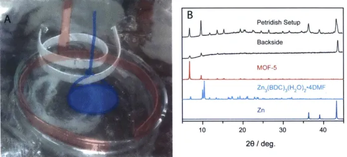
Figure S 1.6. Image and sample PXRD patterns from the Pt-ring/H-cell setup ... 92
Figure S 1.7. Image and sample PXRD patterns from a petridish setup... 92
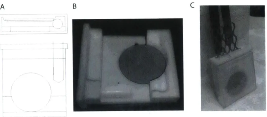
Figute S 1.8. Sample and setup images of PPD 2" ... 93
Figure S1.9. Schematics of PPD 3rd...94
Figure S 1.10. Images and sample PXRD pattern from PPD 3rd ... 94
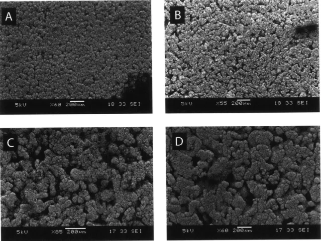
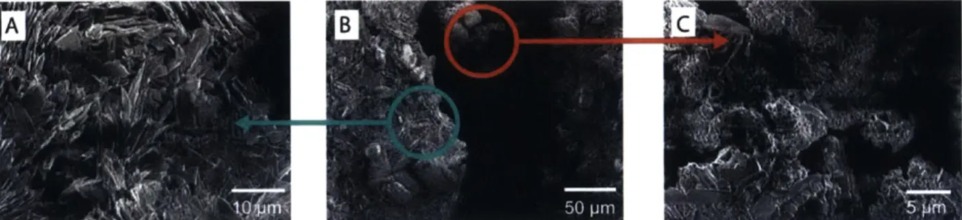
Figure S 1.11. Surface SEM images of PSS samples after deposition ... 95
Figure S 1.12. Cross section SEM images of a PSS sample after deposition ... 95
Figure S 1.13. Schematics of the single gas permeation setup ... 96
Figure S1.14. Permeation data of the PSS samples ... 97
Figure S2.1. First cycle in cyclic voltammograms of NaNO3 on FTO at 10 mV/s...101
Figure S2.2. PXRD patterns of 30-min deposition sample... 102
Figure S2.3. PXRD patterns of samples with various deposition time... 103
Figure S2.4. Linear calibration of Griess reagent determine of N02... 104
Figure S2.5. A dditional X PS survey scans ... 105
Figure S2.6. SEM images of samples with various deposition time...107
Figure S2.7. SEM images of samples with and without stirring... 110
Figure S2.8. PXRD patterns of samples with and without stirring ... 111
Figure S2.9. FIB SEM im ages of cross-sections ... 112
Figure S2.10. FIB TEM im ages of cross-sections ... 113
Figure S2.11. First three cycles in cyclic voltammograms of NaNO3 on FTO at 100 mV/s ... 114
Figure S2.12. First three cycles in cyclic voltammograms of NaNO3 on Zn at 100 mV/s ... 115
Figure S2.13. Chronoamperogram of anodic stripping at -0.4 V... 116
Figure S2.14. PXRD pattern after anodic stripping ... 117
Figure S3.1. PXRD patterns of samples deposited with Zn(C104)2-6H20 ... 120
Figure S3.2. PXRD patterns of samples deposited with Zn(N03)2-5H20, varied hydration... 121
Figure S3.3. PXRD patterns of samples deposited in DMF-anh, varied counter ions... 122
Figure S3.4. PXRD patterns of samples deposited in DMF-hyd, varied counter ions... 123
Figure S3.6. PXRD patterns of samples deposited in DMF-hyd, varied concentrations... 125
Figure S3.7. PXRD patterns of samples deposited in DMF-anh, varied potentials... 127
Figure S3.8. PXRD patterns of samples deposited in DMF-hyd, varied potentials... 128
Figure S3.9. PXRD patterns of samples deposited at -1.25 V on FTO... 129
Figure S4.1. Cyclic voltammograms of NaNO3 on a Pt button electrode... 133
Figure S4.2. Cyclic voltammograms of H2BDC, Zn(N03)2, and Et3NHCl in a stepwise addition... 134
Figure S4.3. SEM images of samples deposited at -1.00 V, [Et3NHCl] = 300 mM ... 135
Figure S4.4. Simulated PXRD patterns of [Zn3(BDC)4]2- frameworks ... 136
Figure S4.5. Additional views of the X-ray crystal structure of [Zn3(BDC)4]2- frameworks ... 137
Figure S4.6. SEM images of samples deposited at -1.50 V for 1 h, [Et3NHCl] = 350 mM... 138
Figure S4.7. SEM images of samples deposited at -1.50 V for 4 h, [Et3NHC] = 350 mM... 139
Figure S4.8. PXRD patterns of samples deposited from -1.40 V to -1.70 V for 30 minutes ... 140
Figure S4.9. PXRD patterns of samples deposited from -1.10 V to -1.70 V for 30 minutes ... 141
Figure S4.10. SEM images of samples deposited at -1.50 V for 30 min, [Et3NHCl] = 100 mM... 142
Figure S4.11. SEM images of samples deposited at -1.70 V for 30 min, [Et3NHCl] = 100 mM... 143
Figure S4.12. PXRD patterns of samples deposited at -1.70 V for 30 minutes ... 144
Figure S4.13. Simulated reference PXRD patterns and their Miller indices ... 145
Figure S4.14. PXRD patterns of a sample deposited at -2.00 V, [Et3NHCl] = 350 mM ... 146
Figure S4.15. SEM images of samples deposited at -1.10 V for 6 h, then at -1.70 V for 5 min ... 147
Figure S4.16. SEM images of samples deposited at -1.50 V for 5 min and 15 min, [Et3NHC] = 350 mM ... 14 9 Figure S4.17. PXRD patterns of samples deposited at -1.50 V, Conc. #1 ... 150
Figure S4.18. SEM images of samples deposited at -1.50 V, Conc. #1... 151
Figure S4.19. PXRD patterns of samples deposited at -1.50 V, Conc. #2... 153
Figure S4.20. SEM images of samples deposited at -1.50 V, Conc. #2... 154
Figure S4.21. PXRD for samples deposited at -1.50 V, Conc. #3 ... 156
Figure S4.22. PXRD patterns of samples deposited with NaNO3 and Zn(C104) 2-6H20 ... 158
Figure S4.23. PXRD patterns of samples deposited with Et3NHCl and Zn(C104) 2-6H20... 159
Figure S4.24. PXRD patterns of samples deposited from control reactions at -1.10 V and -1.50 V ... 160
Figure S4.25. Additional PXRD patterns of samples deposited from a potential step ... 161
Figure S5.1. Crystal structure of (TBA)HBDC ... 165
Figure S5.2. PXRD patterns of samples deposited with metathesized Zn(N0 3)2 for 90 min ... 166
Figure S5.3. Chronoamperogram for deposition with metathesized Zn(N03)2 ... . . .. . . .. . . .. . .. . 167
Figure S5.4. PXRD patterns of samples deposited with metathesized Zn(N0 3)2 for 15 and 45 min ... 168
Figure S5.6. Chronoamperogram for deposition with Zn(ClO4)2-6H20... 170
Figure S5.7. Cyclic voltammograms of H2BDC on a Zn electrode in DMF-anh ... 171
Figure S5.8. Cyclic voltammograms of H2BDC on a Zn electrode in DMF-hyd... 172
Figure S5.9. PXRD patterns of samples deposited with H2BDC and TBAP on Zn electrodes ... 173
Figure S5.10. PXRD patterns of samples deposited with H2BDC and NaNO3on Zn electrodes...174
Figure S5.11. PXRD Figure S5.12. PXRD Figure S5.13. PXRD Figure S5.14. PXRD Figure S5.15. PXRD Figure S5.16. PXRD Figure S5.17. PXRD Figure S5.18. PXRD Figure S5.19. PXRD Figure S5.20. PXRD Figure S5.21. PXRD Figure S5.22. PXRD Figure S5.23. PXRD Figure S5.24. PXRD patterns of patterns of patterns of patterns of patterns of patterns of patterns of patterns of patterns of patterns of patterns of patterns of patterns of patterns of Zn electrodes before and after ethanoal rinse ... 175
precipitates from caustic suspensions of TBAOH and H2BDC... 176
Zn electrodes after sonication in caustic suspensions... 177
samples deposited with Zn(C104)2-6H20 for 15 and 45 min... 178
samples deposited with Zn(C104)2-6H20 under N2 and 02, 30 min ... 179
samples deposited with Zn(C104)2-6H20 under N2 and 2 ... 180
samples deposited with Zn(C104)2-6H20 under N2 and 02 ... 181
samples deposited with Zn(CF303)2 under 2 ... 182
samples deposited with Zn(CF303)2 under N2 ... .. . . .. . . .. . . 183
samples deposited with Zn(C104)2-6H20 for 30 min... 184
samples deposited with Zn(C104)2-6H20 for 1 h... 185
samples deposited with Zn(N03)2-5H20 under 02... 186
samples deposited with Zn(N03)2-5H20 under 02, potential dial ... 187
List of Schemes
Schem e 1.1. M OF-electrode interfaces... 15
Scheme 2.1. Typical crystallization routes for the synthesis of carboxylate-based MOFs... 26
Scheme 2.2. Mechanism for cathodic electrodeposition of crystalline MOFs...27
Scheme 4.1. Cathodically-induced electrochemical deposition of Zn-BDC MOFs ... 58
Scheme 4.2. Formation of a biphasic mixed film and a bilayer mixed film ... 64
List of Tables
Table 3.1. Deposition parameters and solid species identified by PXRD, varied counterions... 49Table S2.1. XPS regional fitting parameters on C, Cl, 0, and Zn ... 106
Table S3.1. Experimental parameters and crystalline phases observed in deposition with varied con centration s ... 126
Table S4.1. Summary of samples deposited with various concentrations of Et3NHCl for various time .148 Table S4.2. Summary of sample deposited with NaNO3 or Et3NHCl at various potentials ... 157
Chapter 1. Electrochemistry in Metal-Organic Frameworks: Progress towards Thin-Film
Devices
1.1 Abstract
The high porosity and the large library of metal-organic frameworks (MOFs) have brought new possibilities to advanced electronic and electrochemical devices. As researchers continue to probe electron transfer reactions at metal nodes, organic linkers, and guest molecules in these novel materials, many challenges remain in interfacing them with traditional electrodes. Thin film processing is a crucial step towards the successful commercial and industrial applications of MOFs, and direct electrochemical fabrication is a versatile method with unique advantages. This chapter summarizes the progress in the fabrication of MOF thin film interfaces with an emphasis on direct electrochemical methods.
1.2 Metal-Organic Frameworks for Electrochemical Applications: Promises and Progress
Metal-organic frameworks (MOFs) are networks of organic ligands and inorganic nodes linked by coordination bonds. They can be conceptualized as the complement of micro- and nanoparticles: ordered arrays containing interconnected and well-defined voids. Because of these voids, MOF lattices can house and interact with various guest molecules, which in turn may induce chemical or physical changes. These unique phenomena have been explored only recently.
Traditionally, the high internal surface area promoted applications of MOFs in the sorption and storage of gases, which have been and still are major research foci.1 Many MOFs exhibit large internal surface areas exceeding 4,000 m2/g, as shown by nitrogen sorption isotherm modeled with the
Brunauer-Emmett-Teller theory. This defining feature has led to a rapid expansion of the field in the past fifteen years. More recently, the inherent structural complexity and vast synthetic flexibility made MOFs truly shine as the next-generation materials for separation, 8 catalysis,9-14 and sensing. '- Beyond high porosity, the ability
to structurally characterize specific functional groups that are appended to the framework allows facile modification and optimization of molecular and bulk properties. Such dynamic features enable rational design of new materials that alter the chemical and physical characteristics for a specific target environment. Notably, there is a growing interest in utilizing MOFs in electronic and electrochemical components for energy storage and signal transduction, among others, many of which rely on having efficient and robust
Making MOFs compatible with electrochemical devices is an ongoing challenge with three foreseeable hurdles. First, the chemical and mechanical stability of these solids can sometimes be inferior to traditional electrode materials, such as noble metals, under standard electrochemical reaction conditions that often involve highly acidic or caustic aqueous solutions. For many MOFs, more thermodynamically favorable acid-base reactions with the solvents cause cleavage of the coordination bond between metal nodes (also called secondary building units, SBUs) and organic linkers, resulting in structural transformations or sometimes complete dissolution. It should be noted, however, that a handful of MOFs are stable even in strongly acidic or caustic aqueous conditions, such as the UiO series with zirconium secondary building units.19 Second, although MOFs became prominent because certain examples in this class maintain permanent porosity upon removal of guest solvent molecules, permanent porosity is not the norm. In fact, many MOFs do not retain permanent porosity, meaning that the void space is not available after the guest molecules are removed. In these cases, the lattice can collapse to a more stable but compact crystalline structure, or in most cases a completely amorphous state. Again, even for those materials that are not stable to typical evacuation routes, more gentle solvent removal techniques, such as treatment with supercritical
C02, can remove occluded solvents to afford porous materials. 201
Finally, MOFs are traditionally poor electrical conductors due to a lack of efficient charge carrier pathways incorporated in crystalline structures. In order to observe meaningful chemical changes in the MOF by electrochemistry, the electrode is required to maintain close contacts with the MOF. In this sense, a thin-film geometry on a high surface area substrate is ideal because signal transduction is optimized. Recent breakthroughs have shrewdly integrated more mobile pathways and engineered systems with greater electric conductivity.2 23
However, based on current case studies, many improvements are still needed to integrate MOFs into existing electronic and
electrochemical devices.
1.3 MOFs, Electrodes, and Thin Films
Because MOFs are usually synthesized as crystalline powders or crystallites, probing their electrochemical properties often requires attaching the loose powders or crystallites to an electrode or otherwise forming a MOF-modified electrode surface. How a given material interfaces with the electrode surface is obviously extremely important in dictating the electronic coupling between the electrode and the MOF, and thus the electrochemical behavior of the latter. Ideally, the interface should maintain ohmic contact while remaining chemically and mechanically robust. Most importantly, the MOF-modified electrodes should display a characteristic response stemming from the framework that is different from the background electrochemical response from the bare electrode. In this context, the direct fabrication of MOF thin films on the electrodes provides a convenient means to obtain responsive and reliable interfaces.
1.3.1 The MOF-Electrode Interface
The interface between a given MOF and the electrode falls into two categories: neat interfaces and
composite interfaces (Figure 1.1). Neat interfaces directly link the MOFs to the electrode surface either by
Van der Waals interactions or by anchored functional groups. Forming neat interfaces is often conceptually simple: functionalization methods include direct mechanical stabilization,24-27 solvothermally crystallized layers,28-3
1 and drop-cast-dry of solvent-suspended crystallites to form surface adsorbed species. 3 2-3
s Alternatively, functional groups can be covalently attached to the electrode surface to provide anchor points for MOFs. Surface functionalization methods may include radical coupling with aromatic diazonium molecules or self-assembly of alkyl monolayers.36 3 8
Composite interfaces are those that employ mixtures of MOFs with other additives meant to either
enhance charge or electrolyte transport, such as electrically conductive carbonaceous materials or ionically conductive membranes, or to simply provide more mechanically and chemically robust films, such as a
Neat Interface
Composite Interface
B C
III
Electrically Conducting Supports
lonically Conducting Supports
Immobilizers and Binders
Scheme 1.1. Illustrations of a neat interface, where MOF crystals are directly attached to an electrode, and a composite interface, where MOF crystals are attached to an electrode through additives. The additives in a composite interface may serve one of three functions: (A) an electrical conducting support that facilitates charge
transfer between the electrode and the MOF crystals, (B) an ionic conducting support that facilitates ion transport to a surface to maintain charge neutrality, and (C) an immobilizer or a binder that exerts physical adhesive force to anchor the MOF crystals to the electrode.
resin or polymer that provides an adhesive force. Both motivations for developing MOF composite films contribute to an enhanced electrochemical response.
Electrically conducting supports. These components can establish more intimate contact and facilitate
electron transfer between the electrode surface and the MOF crystallites. In particular, graphite or carbon black powders are most typically used. Other carbonaceous supports, such as carbon nanotubes or reduced graphene-oxide/graphene, will play greater roles in the foreseeable future.36'39-4'2 Following literature precedents of carbon paste electrodes, MOFs have been suspended in graphite powder and a pasting liquid, such as paraffin oil, to form paste composites or inks that can be applied to electrodes.42
,43 Overall, the extended aromatic structure in graphite is very compatible with often arene-rich MOFs and facilitates adsorption using the drop-cast-dry method. Aside from adsorption via Van der Waals forces, covalently anchored functional groups with available coordination sites can also come into play with chemically modified carbon surfaces. For instance, Jahan et al. decorated reduced graphene oxide with pyridine groups to bind iron porphyrins. This method enhanced charge transfer and ultimately the catalytic properties of the graphene and porphyrin MOF composite. With electrode surface modification by MOFs or carbonaceous materials, the active electrode area could differ significantly before and after modification. A point of caution is that the true current density for a given electrochemical process may be difficult to discern if the increase in current response is partly due to the increase in the active electrode surface area from the carbon incorporation (e.g. capacitive current).
Ionically conducting supports. Porous materials such as Nafion and poly(methylacrylate) can allow
greater cation mobility throughout the composite interface.3 0
,4 445 Nafion is a sulfonated polymer that has high proton conductivity, chemical resistance, and mechanical stability. It can also be modified by exchanging with other cations for applications demanding some degrees of ion selectivity. However, non-exchanged Nafion contains highly acidic sulfonic acid groups and absorbs moisture very effiiently, which can pose a stability challenge for some MOFs if not handled properly.
Immobilizers and binders. Additives such as resins, polymers, and gel coatings may be necessary if
crystallites have low mechanical stability or if the interfacial electrical contact is poor.3 046,47 Similarly, with
magnetic forces, MOF-incorporated Fe304 nanoparticles can be anchored on a specially constructed glassy carbon electrode with a backside magnet.48
Regardless of the type of immobilizer, all are often utilized in conjunction with electrolytes and ionic conductors to form self-supported gel layers.3 0,47,49
Immobilizers imitate a neat electrode-MOF interface and should be chemically and electrochemically inert to both the MOF and the electrode. Ideally, a minimal amount of immobilizer is applied, so the exposed crystallite surface area and consequentially the associated electron/ion transport properties do not change significantly.
The effectiveness of fabricating an electrode-MOF interface is highly dependent on both the properties of the MOF crystallites such as size, surface termination, and ligand aromaticity, and the properties of the electrodes such as hardness, geometry, and hydrophilicity. Reliable observation of electrochemical activity from a MOF requires a shrewd choice of the electrode-MOF interface in addition to more mundane considerations such as the selection of solvents, electrolyte salts, and reference electrodes. Finally, it is imperative that the stability and identity of the final electrode-MOF interface should be investigated thoroughly to establish stability and material uniformity before, during, and after a given study.
1.3.2 MOF Thin Films
In order to integrate MOFs into electronic and electrochemical devices by modern microfabrication techniques, such as lithographic patterning and contact printing, a thin-film geometry is often required for making membranes, coatings, and layered composites. Other industrial applications, for example catalysis and gas separation, also find thin film geometry beneficial. Under large flow throughputs, maximizing heterogeneous interactions requires not only large internal surface area but also large external surface area, which makes microporous functional coatings on hierarchical supports the most desirable. To date, MOF thin films have been created in a variety of ways for applications such as gas separation membranes, electrochemical sensors, and energy conversion devices. Several reviews summarize progress in these areas and are not elaborated here.505 4
Overall, MOF thin films are divided into two categories based on the size of their crystalline domains: single-crystal thin films and polycrystalline films. Single-crystal films offer precisely controlled crystal orientation but their synthesis is very system-dependent. At the other end of the spectrum, there are the polycrystalline films, which are agglomerates of crystallites in random orientations. In these configurations, the lack of strong adhesion at the grain boundaries can lead to structural weaknesses and electronic defects. However, the less stringent orientation requirement has led to a more robust development of techniques aimed at fabricating polycrystalline thin films. Many of the techniques for fabricating polycrystalline films have been applied broadly to various metal-ligand pairs, as they generally yield faster fabrication time.
Access to single-crystal MOF thin films usually involves one of two routes: layer-by-layer liquid epitaxy on a functionalized substrate, and liquid interface lifting. In layer-by-layer liquid epitaxy, a self-assembled monolayer, such as alkylthiol on gold, is first deposited on a smooth surface.55-59 Afterwards,
solutions of metal and ligand precursors are washed over the modified surface in succession, yielding two-dimensional slices of MOFs. In contrast, the liquid interface lifting technique utilizes a Langmuir-Blodgett trough to slowly peel a hydrophobic layer forming on a hydrophilic surface (such as aromatic organic molecules on aqueous solutions) or vice versa.51,0-62 Multiple passes through the solution media allow growth of the stacked layers as a three-dimensional solid. These single-crystalline layers exhibit highly
controlled orientation able to exhibit orientation-dependent guest sorption properties." Thin films obtained by these methods may be readily integrated into electrochemical devices. One example features a redox electron transfer mediator with the encapsulation of ferrocene molecules in the MOF thin film.3 8 Although clearly effective, these methods have not been applied to sufficient systems to demonstrate generality yet, while the multistep processes they usually comprise makes them tedious and time-consuming. Mechanical automation in a flow reactor setup may lead to a wider utilization of these techniques, but the development of other, more streamlined and faster techniques is still important.
The synthesis of polycrystalline MOF thin films has also been dominated by only a few popular techniques thus far, such as direct solvothermal crystallization, secondary seeded growth, and crystallite assembly.4 Because polycrystalline films have randomly oriented crystallites by definition, the surface roughness tends to be tens or hundreds of nanometers if not greater, depending on the crystallite size. Secondary seeded growth disperses a layer of MOF nanocrystals or other materials as sites of nucleation such that the subsequent synthesis of MOFs will create a densely packed intergrown layer rather than segregated individual crystals. Crystallite assembly takes nanocrystals in a colloidal suspension and casts the crystallites on to the surface. Without anchoring functional groups, films synthesized through crystallite assembly and even -seeded growth tend to delaminate from the surface. However, when the underlying surface is pre-functionalized with anchoring groups such as benzoates, the composite interface created may not retain the desired electronic contact. In the case of direct solvothermal crystallization where crystallites are allowed to nucleate on the electrodes, even though there are no specific anchoring groups on the electron transfer from the electrode to the MOF is typically more facile because it is not influenced by the nature of the anchoring group, as is the case with crystallite assembly or seeded growth. In fact, our group has shown that direct solvothermal synthesis can create uniform, micron-scale-thick, and redox-active layers of MOFs
on fluorine- or indium-doped tin oxide, in the absence of any structure-directing or anchoring groups.31 1.3.3 Electrochemical Fabrication of MOF Thin Films
El-ectrochemical methods are best suited to address the challenge of interfacing MOFs with electrode surfaces.6 3'64 Generally, electrodeposition methods find wide utility in industrial settings, where chemical carriers of the reductive or oxidative equivalents could be omitted. At the same time, these methods enable deposition of submicron-sized features only at the electrode-solution interface, do not require line-of-sight instrumental setups, as physical vapor deposition techniques do for instance, and can therefore be used to build conformal coatings on electrodes of virtually any geometry and surface area. Furthermore, because any exposed electrode surface is electrochemically active, the deposition of non-conductive, electrode-passivating films such as MOFs allows for in-situ repairing of defects such as cracks and pinholes. Finally, the electrochemical nature of the process offers additional advantages in that the deposition progress can
be monitored by the amount of passed charge, giving control over film thickness. Indeed, because of scalability, ease of processing, and the ability to work at room temperature, the electrochemical synthesis based on anodic dissolution of the metal component-Cu, Al, Zn-is the method of choice for the
large-scale production of some of the commercially-available MOFs.6 5,6 6
The first case of electrochemically prepared MOF was the anodic dissolution of a Cu electrode in the presence of H3BTC (BTC3-: 1,3,5-benzenetricarboxylate) linkers to precipitate HKUST-l (Cu3(BTC)2).
65
-68 De Vos and coworkers have shown that the electrode surface could be easily patterned with HKUST-1 thin films by physically blocking solution access partially with nonconductive masks.66 In subsequent work,
the same technique afforded dense and uniform thin films on copper mesh substrates.68 Since then, many other frameworks, including MIL-100(Fe),67 MIL-1 OO(Al),6 5 MIL-53(Al), MIL-53-NH2(Al), ZIF-8 (Zn(MIM)2; MIM-: 2-methylimidazolate), Zn3(BTC)2-12H20,69 Zn2(PTP)2(SO4) -H20 (PTP-: 4-(5-(pyrazol-4-ylato)-H-1,2,4-triazol-3-yl)pyridine),70
and MOF-5 (MOF-5, Zn40(BDC)3),71 have been
synthesized in a similar manner by oxidizing an electrode of the appropriate metal in the presence of the ligand. These MOF films can be readily integrated into devices. For example, films of luminescent Tb-doped Gd-BTC and Zn-BTC made by anodic dissolution of Zn and lanthanide metals were reported to detect a TNT analog, 2,4-dinitrotoluene (DNT).72
In addition to the anodic dissolution method, other approaches to electrochemical syntheses showed versatility in fabricating more complex structures. For instance, by placing a metal piece into an electric field established in solution, a difference in polarization could be utilized to induce ZIF-8 and HKUST-1 formation selectively on one part of the metallic substrate to form Janus-type composites.73
In another case, by using the electrophoretic force in a low polarity and non-ionizing solvent, selective and patternable formation of MOF thin films was observed.74
Because anodic dissolution is limited to metallic substrates, a more universal approach is needed to synthesize MOF thin films on electrode surfaces. Utilizing cathodic conditions could provide another path to access MOFs directly on electrodes. Instead of electrolyzing the metallic electrode to obtain flux of metal ions for precipitation, probase species, such as N03-, can be reduced to provide base equivalents that facilitate ligand deprotonation/deprotection for the subsequent precipitation. Our lab has pioneered this technique to show its feasibility and scope in the field of MOFs, and it has been well-received in the community. For example, Yang and coworkers prepared [Tb2(BDC)3(H20)4]n thin film on FTO for Cu>
sensing (BDC2 : 1,4-benzenedicarboxylate) and also Eu(HBPTC)(H2O)2-2DMF thin film for anion sensing
(HBPTC3-: monoprotonated benzophenone-3,3',4,4'-tetracarboxylate). 7 76 Recently, Ameloot and
coworkers have reported both anodic and cathodic approaches to deposit patterned films of UiO-66 for miniaturized sorbent traps.77 In the following chapters, we will describe the synthetic methodology for the
cathodic deposition of MOF-5/Zn composite on FTO (FTO: fluorine-doped tin oxide) electrodes at room temperature in just 15 minutes.78 Then, we will show that more complex architectures, such as biphasic
mixture or bilayer composites, could be realized with sequenced potential steps.79 Furthermore, systematic
studies aimed at a mechanistic understanding of the electrochemical and chemical transformations occurring under cathodic bias in our deposition baths will be outlined.80 We expect that the cathodic
approach towards MOF thin film synthesis will be an important asset in the toolbox of MOF-based device fabrication.
1.4 References
(1) Murray, L. J.; Dincd, M.; Long, J. R. Chem. Soc. Rev. 2009, 38 (5), 1294-1314. (2) Suh, M. P.; Park, H. J.; Prasad, T. K.; Lim, D.-W. Chem. Rev. 2012, 112 (2), 782-835.
(3) Sumida, K.; Rogow, D. L.; Mason, J. A.; McDonald, T. M.; Bloch, E. D.; Herm, Z. R.; Bae, T.-H.;
Long, J. R. Chem. Rev. 2012, 112 (2), 724-78 1.
(4) Brown, A. J.; Brunelli, N. A.; Eum, K.; Rashidi, F.; Johnson, J. R.; Koros, W. J.; Jones, C. W.;
Nair, S. Science 2014, 345 (6192), 72-75.
(5) Peng, Y.; Li, Y.; Ban, Y.; Jin, H.; Jiao, W.; Liu, X.; Yang, W. Science 2014, 346 (6215), 13
56-1359.
(6) Shah, M.; McCarthy, M. C.; Sachdeva, S.; Lee, A. K.; Jeong, H.-K. Ind Eng. Chem. Res. 2012, 51
(5), 2179-2199.
(7) Li, J.-R.; Sculley, J.; Zhou, H.-C. Chem. Rev. 2012, 112 (2), 869-932. k) i, J.-R.; IKuppler, R_. J.; hou, H.-C. Chem. Soc.
Aev.
2009,
3 (), 147--1504.(9) Mueller, U.; Schubert, M.; Teich, F.; Puetter, H.; Schierle-Arndt, K.; Pastrd, J. J Mater. Chem. 2006, 16 (7), 626.
(10) Ma, L.; Abney, C.; Lin, W. Chem. Soc. Rev. 2009, 38 (5), 1248-1256.
(11) Corma, a; Garcia, H.; Llabres i Xamena, F. X. Chem. Rev. 2010, 110 (8), 4606-4655. (12) Yoon, M.; Srirambalaji, R.; Kim, K. Chem. Rev. 2012, 112 (2), 1196-1231.
(13) Gascon, J.; Corma, A.; Kapteijn, F.; Llabrds i Xamena, F. X. A CS Catal. 2014, 4 (2), 361-378. (14) Liu, J.; Chen, L.; Cui, H.; Zhang, J.; Zhang, L.; Su, C.-Y. Chem. Soc. Rev. 2014, 43 (16),
(15) Heine, J.; MUller-Buschbaum, K. Chem. Soc. Rev. 2013, 42 (24), 9232-9242.
(16) Kreno, L. E.; Leong, K.; Farha, 0. K.; Allendorf, M.; Van Duyne, R. P.; Hupp, J. T. Chem. Rev.
2012, 112 (2), 1105-1125.
(17) Cui, Y.; Yue, Y.; Qian, G.; Chen, B. Chem. Rev. 2012, 112, 1126-1162. (18) Morozan, A.; Jaouen, F. Energy Environ. Sci. 2012, 5 (11), 9269-9290.
(19) Cavka, J. H.; Jakobsen, S.; Olsbye, U.; Guillou, N.; Lamberti, C.; Bordiga, S.; Lillerud, K. P. J.
Am. Chem. Soc. 2008, 130 (42), 13850-13851.
(20) Nelson, A. P.; Farha, 0. K.; Mulfort, K. L.; Hupp, J. T. J. Am. Chem. Soc. 2009, 131 (2), 458-460.
(21) Cooper, A. I.; Rosseinsky, M. J. Nat. Chem. 2009, 1 (1), 26-27.
(22) Sheberla, D.; Sun, L.; Blood-Forsythe, M. A.; Er, S.; Wade, C. R.; Brozek, C. K.; Aspuru-Guzik, A.; Dinca, M. J. Am. Chem. Soc. 2014, 136 (25), 8859-8862.
(23) Campbell, M. G.; Sheberla, D.; Liu, S. F.; Swager, T. M.; Dinca, M. Angew. Chem. Int. Ed. 2015,
54, 4349-4352.
(24) Leong, C. F.; Chan, B.; Faust, T. B.; D'Alessandro, D. M. Chem. Sci. 2014, 5, 4724-4728.
(25) Halls, J. E.; Hernan-Gomez, A.; Burrows, A. D.; Marken, F. Dalton Trans. 2012, 41, 1475-1480. (26) Miles, D. 0.; Jiang, D.; Burrows, A. D.; Halls, J. E.; Marken, F. Electrochem. Commun. 2013, 27,
9-13.
(27) Halls, J. E.; Ahn, S. D.; Jiang, D.; Keenan, L. L.; Burrows, A. D.; Marken, F. J. Electroanal.
Chem. 2013, 689, 168-175.
(28) Kobayashi, Y.; Jacobs, B.; Allendorf, M. D.; Long, J. R. Chem. Mater. 2010, 22 (14), 4120-4122.
(29) Hirai, K.; Uehara, H.; Kitagawa, S.; Furukawa, S. Dalton Trans. 2012, 41 (14), 3924-3927.
(30) Domenech, A.; Garcia, H.; Dom6nech-Carb6, M. T.; Llabres-i-Xamena, F. Electrochem. Commun. 2006, 8 (12), 1830-1834.
(31) Wade, C. R.; Li, M.; Dincd, M. Angew. Chem. Int. Ed. 2013, 52 (50), 13377-13381.
(32) Kung, C.-W.; Wang, T. C.; Mondloch, J. E.; Fairen-Jimenez, D.; Gardner, D. M.; Bury, W.;
Klingsporn, J. M.; Barnes, J. C.; Van Duyne, R.; Stoddart, J. F.; Wasielewski, M. R.; Farha, 0. K.;
Hupp, J. T. Chem. Mater. 2013, 25 (24), 5012-5017.
(33) Mazzeo, P. P.; Maini, L.; Braga, D.; Valenti, G.; Paolucci, F.; Marcaccio, M.; Barbieri, A.;
Ventura, B. Eur. J Inorg. Chem. 2013, 2013 (25), 4459-4465.
(35) Lei, J.; Qian, R.; Ling, P.; Cui, L.; Ju, H. TrAC Trends Anal. Chem. 2014, 58, 71-78. (36) Jahan, M.; Bao,
Q.;
Loh, K. P. J. Am. Chem. Soc. 2012, 134 (15), 6707-6713.(37) Dragasser, A.; Shekhah, 0.; Zybaylo, 0.; Shen, C.; Buck, M.; W611, C.; Schlettwein, D. Chem.
Commun. 2012, 48 (5), 663-665.
(38) Heinke, L.; W611, C. Phys. Chem. Chem. Phys. 2013, 15 (23), 9295-9299.
(39) Ferey, G.; Millange, F.; Morcrette, M.; Serre, C.; Doublet, M.-L.; Grenbche, M.; Tarascon,
J.-M. Angew. Chem. Int. Ed. 2007, 46 (18), 3259-3263.
(40) Fateeva, A.; Horcajada, P.; Devic, T.; Serre, C.; Marrot, J.; Greneche, J.-M.; Morcrette, M.;
Tarascon, J.-M.; Maurin, G.; Ferey, G. Eur. J. Inorg. Chem. 2010, 2010 (24), 3789-3794.
(41) Hinogami, R.; Yotsuhashi, S.; Deguchi, M.; Zenitani, Y.; Hashiba, H.; Yamada, Y. ECS
Electrochem. Lett. 2012, 1 (4), H17-H 19.
(42) Li, Y. Y.; Huangfu, C.; Du, H.; Liu, W.; Li, Y. Y.; Ye, J. J. Electroanal. Chem. 2013, 709, 65-69.
(43) Wang, Y.; Wu, Y.; Xie, J.; Hu, X. Sensors Actuators B Chem. 2013, 177, 1161-1166.
(44) Kozachuk, 0.; Yusenko, K.; Noei, H.; Wang, Y.; Walleck, S.; Glaser, T.; Fischer, R. A. Chem.
Commun. 2011, 47 (30), 8509-8511.
(45) Gong, Y.; Hao, Z.; Meng, J.; Shi, H.; Jiang, P.; Zhang, M.; Lin, J. ChemPlusChem 2014, 79 (2),
266-277.
(46) Dom6nech, A.; Garcia, H.; Domenech-Carb6, M. T.; Llabres-i-Xamena, F. J Phys. Chem. C 2007, 111 (37), 13701-13711.
(47) Usov, P. M.; Fabian, C.; D'Alessandro, D. M. Chem. Commun. 2012, 48 (33), 3945-3947.
(48) Hu, L.; Wu, N.; Zheng, J.; Xu, J.; Zhang, M.; He, P. Anal. Sci. 2014, 30 (6), 663-668.
(49) Yang, L.; Kinoshita, S.; Yamada, T.; Kanda, S.; Kitagawa, H.; Tokunaga, M.; Ishimoto, T.; Ogura,
T.; Nagumo, R.; Miyamoto, A.; Koyama, M. Angew. Chem. Int. Ed. 2010, 49 (31), 5348-535 1. (50) Zacher, D.; Shekhah, 0.; W611, C.; Fischer, R. A. Chem. Soc. Rev. 2009, 38 (5), 1418-1429.
(51) Makiura, R.; Motoyama, S.; Umemura, Y.; Yamanaka, H.; Sakata, 0.; Kitagawa, H. Nat. Mater.
2010, 9 (7), 565-571.
(52) Shekhah, 0.; Liu, J.; Fischer, R. A.; W611, C. Chem. Soc. Rev. 2011, 40 (2), 1081-1106.
(53) Bradshaw, D.; Garai, A.; Huo, J. Chem. Soc. Rev. 2012, 41 (6), 2344-2381. (54) Betard, A.; Fischer, R. A. Chem. Rev. 2012, 112 (2), 1055-1083.
(55) Liu, B.; Tu, M.; Fischer, R. A. Angew. Chem. Int. Ed. 2013, 52 (12), 3402-3405.
(56) Shekhah, 0.; Wang, H.; Kowarik, S.; Schreiber, F.; Paulus, M.; Tolan, M.; Sternemann, C.; Evers,
F.; Zacher, D.; Fischer, R. A.; W611, C. J. Am. Chem. Soc. 2007, 129 (49), 15118-15119.
(57) Hermes, S.; Schr6der, F.; Chelmowski, R.; W611, C.; Fischer, R. A. J Am. Chem. Soc. 2005, 127 (40), 13744-13745.
(58) Zacher, D.; Yusenko, K.; Betard, A.; Henke, S.; Molon, M.; Ladnorg, T.; Shekhah, 0.; SchUpbach,
B.; de los Arcos, T.; Krasnopolski, M.; Meilikhov, M.; Winter, J.; Terfort, A.; W611, C.; Fischer,
R. A. Chem. Eur. J. 2011, 17 (5), 1448-1455.
(59) Shekhah, 0.; Hirai, K.; Wang, H.; Uehara, H.; Kondo, M.; Diring, S.; Zacher, D.; Fischer, R. A.; Sakata, 0.; Kitagawa, S.; Furukawa, S.; W611, C. Dalton Trans. 2011, 40 (18), 4954-4958. (60) Motoyama, S.; Makiura, R.; Sakata, 0.; Kitagawa, H. J. Am. Chem. Soc. 2011, 133 (15),
5640-5643.
(61) Otsubo, K.; Haraguchi, T.; Sakata, 0.; Fujiwara, A.; Kitagawa, H. J Am. Chem. Soc. 2012, 134 (23), 9605-9608.
(62) Xu, G.; Yamada, T.; Otsubo, K.; Sakaida, S.; Kitagawa, H. J. Am. Chem. Soc. 2012, 134 (40),
16524-16527.
(63) Gurrappa, I.; Binder, L. Sci. Technol. Adv. Mater. 2008, 9 (4), 043001.
(64) Al-Kutubi, H.; Gascon, J.; Sudh6lter, E. J. R.; Rassaei, L. ChemElectroChem 2015.
(65) Joaristi, A. M.; Juan-Alcaniz, J.; Serra-Crespo, P.; Kapteijn, F.; Gascon, J. Cryst. Growth Des. 2012, 12 (7), 3489-3498.
(66) Ameloot, R.; Stappers, L.; Fransaer, J.; Alaerts, L.; Sels, B. F.; De Vos, D. E. Chem. Mater. 2009,
21 (13), 2580-2582.
(67) Campagnol, N. N.; Van Assche, T.; Boudewijns, T.; Denayer, J.; Binnemans, K.; De Vos, D.;
Fransaer, J. J. Mater. Chem. A 2013, 1 (19), 5827-5830.
(68) Van Assche, T. R. C.; Desmet, G.; Ameloot, R.; De Vos, D. E.; Terryn, H.; Denayer, J. F. M.
Microporous Mesoporous Mater. 2012, 158, 209-213.
(69) Li, W.-J.; LU, J.; Gao, S.-Y.; Li, Q.-H.; Cao, R. J. Mater. Chem. A 2014, 2, 19473-19478.
(70) Zhang, M. M.; Gong, Y.; Zhang, P.; Shi, H. F.; Lin, J. H. Dalton Trans. 2014, 43, 17129-17135.
(71) Yang, H. M.; Song, X. L.; Yang, T. L.; Liang, Z. H.; Fan, C. M.; Hao, X. G. RSCAdv. 2014, 4
(30), 15720-15726.
(72) Campagnol, N.; Souza, E. R.; De Vos, D. E.; Binnemans, K.; Fransaer, J. Chem. Commun. 2014, 50 (83), 12545-12547.
(73) Yadnum, S.; Roche, J.; Lebraud, E.; Ndgrier, P.; Garrigue, P.; Bradshaw, D.; Warakulwit, C.;
Limtrakul, J.; Kuhn, A. Angew. Chem. Int. Ed. 2014, 53 (15), 4001-4005.
(74) Hod, I.; Bury, W.; Karlin, D. M.; Deria, P.; Kung, C. W.; Katz, M. J.; So, M.; Klahr, B.; Jin, D.; Chung, Y. W.; Odom, T. W.; Farha, 0. K.; Hupp, J. T. Adv. Mater. 2014, 26 (36), 6295-6300. (75) Liu, H.; Wang, H.; Chu, T.; Yu, M.; Yang, Y. J. Mater. Chem. C 2014, 2 (41), 8683-8690.
(76) Wang, Y.; Chu, T.; Yu, M.; Liu, H.; Yang, Y. RSCAdv. 2014, 4, 58178-58183.
(77) Stassen, I.; Styles, M.; Van Assche, T.; Campagnol, N.; Fransaer, J.; Denayer, J.; Tan, J.-C.;
Falcaro, P.; De Vos, D.; Ameloot, R. Chem. Mater. 2015, 27 (5), 1801-1807.
(78) Li, M.; Dincd, M. J. Am. Chem. Soc. 2011, 133 (33), 12926-12929.
(79) Li, M.; Dincd, M. Chem. Sci. 2014, 5 (1), 107-111.
Chapter 2. Cathodic Electrodeposition: Fabrication and Characterization of MOF-5/Zn
Composites on Fluorine-doped Tin Oxide Electrodes
2.1 Abstract
Electroreduction of oxoanions affords hydroxide equivalents that induce selective deposition of crystalline MOFs on conductive fluorine-doped tin oxide surfaces. The method is illustrated by cathodic electrodeposition of a composite containing Zn40(BDC)3 (MOF-5, BDC = 1,4-benzenedicarboxylate),
which is deposited at room temperature in only 15 min. Although many crystalline phases are known in the Zn2+/BDC2- system, MOF-5 is the only one observed under these conditions. This fast and mild method of
synthesizing MOFs is amenable to direct surface functionalization and could impact applications requiring conformal coatings of these materials, such as gas separation membranes and electrochemical sensors.
2.2 Introduction
Owing to their high surface areas, regular pore sizes and pore shapes, and potential for chemical tunability, MOFs have enjoyed tremendous popularity in recent years. Among many proposed applications, the most prominent uses are in gas storage,1-3 gas separation,"4 catalysis,7-12 and luminescent sensors.13-15 Many anticipated applications require that these materials be deposited on various surfaces, for instance as membranes for gas separation or thin films in sensors.'6-8 However, this requirement poses significant difficulties, because bulk MOFs are made as brittle crystals or insoluble powders that are not amenable to common surface processing techniques. To address this issue, membrane or thin film growth techniques initially developed for zeolites and molecular materials, such as seeded and epitaxial growth, have recently been adapted to MOFs.18"9 However, the development of facile and generally applicable methods of growing frameworks on surfaces remains an open challenge with significant implications in gas separation and electrochemical sensing, among others.
In trying to develop new methods to integrate MOFs with surfaces, we noted that in-situ deprotonation of neutral ligands is a key requirement for crystallizing materials based on anionic ligands. Indeed, the synthesis of virtually all frameworks containing carboxylates or azolates, for instance, starts from the respective carboxylic acids or azoles (see Scheme 2. 1).20,21 To optimize crystal growth, base equivalents
must be introduced very slowly either by vapor diffusion, as in the original synthesis of MOF-5,22 or by the in-situ formation of dialkylamines from dialkylformamides, the more popular approach.23 25 In these cases,
A NEt3 (g) B COW
air air
liquid liquid
(o
slow diffusion Me2 - HO 2~ slowdecomposition
HNEt NEt3() Me2NH2 Me2NH
Ar-CO2H Ar-CO2 Ar-CO2H Ar-CO2
Mnj crystallization M crystallization
Scheme 2.1. Typical crystallization routes for the synthesis of carboxylate-based MOFs: (A) slow vapor diffusion of triethylamine, and (B) slow thermal decomposition ofN,N-dimethylformamide.
because ligand deprotonation takes place in the bulk reaction medium, nucleation and growth of MOF crystals occur indiscriminately on any surface exposed to this medium. Moreover, because the rate of formamide decomposition depends on many factors including metal ion concentration, solution pH, and reaction temperature, it is often difficult to predict the rate at which a given MOF is assembled. As such, reaction times required to form various frameworks vary widely from case to case, and the search for appropriate crystallization conditions becomes the bottleneck in the material discovery process. 26-29
A convenient means to provide base equivalents is the electrochemical reduction of a base precursor (also called a probase). For example, generation of the Bronsted base can be achieved by the reduction of water or oxoanions such as N03 (Scheme 2.2). Cathodic generation of HO- creates a pH gradient near the
electrode surface, which has traditionally been used for electrodepositing metal oxide and hydroxide films.30
-32
In certain cases, however, this method is also utilized to electrodeposit non-oxide materials such as CaHPO4 and CaCO3.33-35 Inspired by these reports, we surmised that cathodic generation of HO- in the
presence of neutral bridging ligands and metal ions should cause ligand deprotonation and consequent growth of MOFs directly on the electrode surface. Moreover, we anticipated that the method should be amenable to many metal-ligand combinations, if the only species relevant to MOF precipitation was the electrochemically deprotonated ligand. Our approach contrasts with anodic dissolution deposition methods that rely heavily on anode corrosion to form metal cations and initiate precipitation, where the identity of the electrode limited the choices of MOFs that could possibly be deposited.36
Proof-of-principle experiments were therefore conducted on the cathodic electrodeposition of Zn40(BDC)3 (MOF-5), arguably one of the most iconic MOF materials.
22
In addition, MOF-5 was also one of the first MOFs that has been accessed with synthetic procedures at room temperature, simplifying the
air
liquid
base delively and crystallizaton are confined to the surface
N~e
Ar-C02H
9,.- n(9 .Ar-CO 2 M"Stffzfo
22
N0
2Scheme 2.2. Mechanism for the cathodic electrodeposition of crystalline MOFs. In contrast with other methods, cathodic electrodeposition should allow accumulation of HO~ anions near the conductive surface, thus confining MOF crystallization to the electrode.
electrochemical reaction appatarus.2 2,37 Furthermore, we noticed that solution syntheses of molecular
clusters Zn40(CO2-R) (R = alkyl or aromatic moieties) historically have only been in basic conditions, 38-40
which implied that a cathodic base-generation method had more in common with literature precedents than an anodic dissolution method.
2.3 Results and Discussion
To determine the reaction conditions for bulk electrolysis, we first probed the electrochemical behavior of each reagent with cyclic voltammetry (CV) on inert fluorine-doped tin oxide (FTO) working electrodes (Dimension 2.5 x 1.0 x 0.22 cm3, L x W x H). In Figure 2.1 A, cyclic voltammograms of NaNO3 and ZnCl2 were obtained in a DMF/H20 (100:1 v/v)41 solution and referenced against a silver-silver cryptand couple
(Ag/Ag(cryptand)'), which is stable in NN-dimethylformamide (DMF).4 2 3 Water was deliberately introduced in all the DMF solutions used for electrochemical experiments, because it is required for hydroxide generation from oxoanions.41
At a scan rate of 100 mV/s, Zn plating from the ZnCl2 solution was observed at -1.00 V. In contrast,
the onset of NO3- reduction did not occur until approximately -1.75 V on FTO, as anticipated for uncatalyzed multielectron redox processes, which usually require large overpotentials.44 Owing to the more anodic Zn plating potential compared to N03- reduction on FTO, we projected that zinc deposition should be favorable at potentials when nitrate began to be reduced, leaving an electrode surface mixed with oxide and metal.
A B 1 mA-cm-2 0.5 mA-cm-2 12 mAcm a -S I I I c i ' I 1 0 -1 -2 1 0 -1 -2 E (vs Ag/Ag(cryptand)*) I V E (vs Ag/Ag(cryptand)+) / V Figure 2.1. (A) Cyclic voltammograms of solutions of NaNO3 (red, 300 mM) and ZnCb2 (blue, 150 mM) on FTO
working electrodes in DMF/H20 (100:1 v/v) with 0.1 M TBAPF, at a scan rate of 100 mV/s. The inset shows a
cyclic voltammogram of a 300 mM NaNO3 solution using a Zn plate working electrode in DMF/H20 (100:1 v/v). Dashed traces represent background CV scans.
(B) A cyclic voltammogram (green) of a 50 mM solution ofH2BDC in a DMF/H20 (100/1, v/v) solution containing
0.1 M TBAPF6 electrolyte obtained at room temperature using an FTO working electrode at a scan rate of 100
m V/s. The black solid trace corresponds to a background CV scan of the solvent.
As a consequence, in a mixed solution containing both Zn2+ and , the overpotential for NO3-reduction would be decreased by the catalytic effect of the electroplated metal deposit.45-8 Indeed, a cyclic voltammogram from a solution of NaNO3 in DMF/H20 (100:1 v/v) using Zn metal foil as the working
electrode showed that the onset of NO3- reduction on Zn was anodically shifted by approximately 250 mV relative to FTO (Figure 2.1 A, inset). This shift in potential suggested that in a MOF-5 deposition bath containing Zn(N03)2 and H2BDC, N03 reduction would occur below -1.50 V. In a control experiment
with H2BDC in DMF/H20 (100:1 v/v), we observed proton reduction at approximately - 1.10 V (Figure 2.1
B). The current density from proton reduction was much smaller than zinc reduction at -1.50 V but still significant. Overall, the cyclic voltammogram of the deposition bath containing Zn(N03)2 and H2BDC
reflected the combination of individual redox events we have observed. Accordingly, a deposition bath was prepared by dissolving Zn(N03)2 and H2BDC in the same DMF/H20 (100:1, v/v) solvent solution
containing TBAPF6 electrolyte, and an FTO electrode immersed in this solution was polarized at a constant
potential of -1.60 V for 15 min. H-cells with frit-separated working and counter compartments were utilized to minimize cross-contamination. During electrolysis, the cathodic current density increased steadily from
-5.41 to -6.56 mA-cm-2, after an initial decay phase of approximately 26 sec (Figure 2.2 B). The increasing
-8E
I
E 0.5 mAcm-2 S-4W CC T3) 0 a I I I I I I I 1 0 -1 -2 0 200 400 600 800 E (vs Ag/Ag(cryptand)+) / V Time / sFigure 2.2. (A) A cyclic voltammogram of a MOF-5 deposition bath in a DMF:H20 (100:1, v/v) solution containing
0.1 M TBAPF6 at a scan rate of 100 m V/s on FTO working electrode. The black solid trace indicates the solvent background, and the purple solid trace corresponds to the deposition bath. [Zn2+] = 200 mM, [NO
3
]
= 400 mM,and [H2BDC] = 50 mM The large cathodic feature with an onset of -i.]] V is ascribed to Zn deposition and proton reduction from H2BDC, while the large anodic feature centered at Ep,a = -0.48 Vis ascribed to Zn stripping.
The smaller anodic feature centered at Epa = -0.86 V is assigned to oxidation of hydrogen formed during the cathodic scan.
(B) Chronoamperogram of electrolyzing a MOF-5 deposition bath prepared from Zn(NO3)2 and H2BDC in a DMF/IH20 (100:1, v/v) solution containing 0.1 M TBAPF. [Zn2
+] = 150 mM, [NO3-] = 300 mM, and [H2BDC] =
50 mM 1.1 x 1.1 cm2
, of an FTO working electrode was exposed to the deposition bath. Immediately after the potential step from open circuit to deposition potential (-1.6 V vs Ag/Ag(cryptand)), the current density peaked at
-6.42 mA -cm2 and underwent a typical exponential decay. In total, 6.5 C of charge were passed.
current density over time suggested that the electrode surface was likely modified for greater activity to overcome any possible passivation events. Typical decay in current density due to the limitation in mass transfer was not observed. After completion, nitrate reduction was subsequently probed using the Griess reagent, which tested positive for the presence of N02- in the post-electrolysis bath.49 To obtain the nitrite concentration post electrolysis, the characteristic absorption at 530 nm was quantified by Beer's Law after constructing a linear calibration curve with solutions of known nitrite concentrations (Figure S2.4).
Figure 2.3 shows the powder X-ray diffraction (PXRD) pattern of the film that was deposited on the FTO electrode during the 15 min electrolysis. The expected patterns identifying SnO2 and Zn metal account for the diffraction peaks at 20 = 26.40, 33.70, and 37.7 and 20 = 36.4', 39.0', and 43.2', respectively. Remarkably, the diffraction pattern simulated from single crystal data of MOF-5 accounts for all the remaining peaks below 20 = 25' from the electrodeposited film. Crystallization of MOF-5 under these conditions demonstrates that cathodic electrodeposition is applicable to the functionalization of surfaces with MOFs. Intriguingly, extending the deposition time to 30 min increased the intensity of the Zn peaks relative to those of MOF-5 (Figure S2.3). We tentatively assign this to the reduction of intra-framework Zn2
+ ions to metallic Zn, as observed for instance in the reduction of Cu2 to metallic Cu in composite


![Figure Si.]. Carbon capture apparatus with the following approaches: (top) Pre-combustion separation](https://thumb-eu.123doks.com/thumbv2/123doknet/14205771.480909/87.918.165.715.96.871/figure-carbon-capture-apparatus-following-approaches-combustion-separation.webp)