HAL Id: in2p3-00591014
http://hal.in2p3.fr/in2p3-00591014
Submitted on 26 Oct 2011
HAL is a multi-disciplinary open access
archive for the deposit and dissemination of
sci-entific research documents, whether they are
pub-lished or not. The documents may come from
teaching and research institutions in France or
abroad, or from public or private research centers.
L’archive ouverte pluridisciplinaire HAL, est
destinée au dépôt et à la diffusion de documents
scientifiques de niveau recherche, publiés ou non,
émanant des établissements d’enseignement et de
recherche français ou étrangers, des laboratoires
publics ou privés.
Fusion-evaporation studies with the Super Separator
Spectrometer (S3) at Spiral2
A. Drouart, A.M. Amthor, D. Boutin, F. Déchery, J.A. Nolen, H. Savajols
To cite this version:
A. Drouart, A.M. Amthor, D. Boutin, F. Déchery, J.A. Nolen, et al.. Fusion-evaporation studies with
the Super Separator Spectrometer (S3) at Spiral2. 5th International Conference FUSION11, May
2011, Saint Malo, France. pp.14004, �10.1051/epjconf/20111714004�. �in2p3-00591014�
Fusion-evaporation studies with the Super Separator spectrometer (S
3) at
Spiral2
A. Drouart1, A. M. Amthor2, D. Boutin2, F. Déchery1, J. A. Nolen3 and H. Savajols2 for the S3 collaboration 1Irfu/SPhN, CEA Saclay, 91191 Gif/Yvette Cedex, France
2GANIL 14000 Caen, France.
3Argonne National Laboratory, Argonne, IL, USA
aPresent address: Bucknell University, Lewisburg, PA, USA
Abstract. The Super Separator Spectrometer S3 is a device designed for experiments with the very high
intensity stable ion beam of the superconducting linear accelerator of the SPIRAL2 facility. Its Physics goals cover the study of radioactive ions produced by fusion-evaporation reactions, like superheavy elements or neutron deficient nuclei close to the proton drip line, but also neutron rich nuclei produced by multi-nucleon transfer reactions as well as ion-ion atomic interactions. It is composed of a two-step separator, with a momentum achromat followed by a mass spectrometer. Superconducting multipole triplets, combining quadruple, sextuple and octupole fields, allow a combination of high transmission and mass resolution. A specific open multipole has been designed to stop the high beam power at the first momentum dispersive plane. A decay spectroscopy detection set-up or a low energy branch can be coupled to S3 for a wide range of studies.
1 Motivation
The superconducting linear accelerator of SPIRAL2 will be able to provide not only deuteron beams, but also intense beams of heavy ions, from carbon to uranium, with energies from 2 to 14 MeV/u. Depending on ion source developments and the nature of the ion, currents up to 1mA could be reached, with a high transmission to the experimental areas and flexible beam energy. This opens new possibilities to study low cross-section reactions and their products. Of specific interest are the fusion-evaporation residues produced with near coulomb barrier energies. Two regions of the nuclear chart are particularly implicated:
- The region of superheavy elements with the ultimate goal of the synthesis of new elements to extend the Periodic Table of Mendeleev. With the expected properties of S3, a 10 femtobarn limit could be reached in
only 3 months of beam time, making possible the synthesis of unknown elements with 120 protons or more. Also, detailed studies (decay spectroscopy, mass measurements, etc.) of “lighter” superheavy nuclei will be possible.
- The region of nuclei at the proton drip line, especially in the region of the self-conjugate doubly-magic nucleus 100Sn considered to be one of the critical
benchmarks of nuclear structure far from the valley of stability.
With the S3 project, it will be possible to produce,
select and study these nuclei using complementary detection methods, like spectroscopy of their decay (e.g. alpha, electron and gamma-ray spectroscopy of 274Ds or
super-allowed beta decay of 108Xe-104Te-100Sn) or by
measurements of ground state properties (e.g. resonant laser spectroscopy of 94Ag, masses of the
neutron-deficient nuclei involved in the astrophysical rp-process, chemistry of superheavy elements, etc.).
Also, at higher energies, multi-nucleon transfer reactions can be used to produce neutron rich nuclei that are not reachable by the fission of uranium. Additional details on the physics cases can be found in [1] and in the Letters of Intent for S3 [2].
This program also has strong synergies with the Atomic Physics community, specifically in interaction studies in the unknown regime of fast ion-slow ion collisions. The project “Fast Ion Slow Ion Collisions” (FISIC) addresses the remaining open question of energy deposition by charged particles in matter that takes place in irradiated materials when the ion stopping power is at its maximum. Of course, better knowledge of the mechanisms involved in this regime would have important outcomes in different domains such as inertial confinement fusion or the characterization of stellar and interstellar plasmas but also when the matter corresponds to living cells as in the case of hadron therapy. The dedicated FISIC set-up will not be described here.
© Owned by the authors, published by EDP Sciences, 2011
This is an Open Access article distributed under the terms of the Creative Commons Attribution-Noncommercial License 3.0, which permits unrestricted use, distribution, and reproduction in any noncommercial medium, provided the original work is properly cited.
EPJ Web of Conferences
2 Characteristics
In order to address these important questions, S3 has to
meet or exceed their challenging experimental requirements.
The very high beam intensities require, first, a target that can sustain the high beam power. For that purpose, the incoming beam profile will have a large vertical size, in order to spread the beam over a larger surface area on the target. Moreover, we will use a high speed rotating wheel to support the thin targets, to reduce the maximum temperature and the effects of radiation damage.
The primary beam must also be physically separated from the nuclei of interest. In S3, the first selection stage
is a p/q (momentum over charge) dispersive plane. It is intended to provide for a first rough rejection of the primary beam (to the level of 10-3) either by stopping the
beam charge states out of acceptance or within the acceptance, if required, using “fingers” to block the geometrically focused beam trajectories. The second selection step is at the achromatic focus at the entrance to the mass spectrometer, where all the nuclei of interest are focussed, while any scattered ions are more randomly distributed. The third level of selection is performed by the mass spectrometer, which has an energy (mv2/q)
dispersive plane and at the end an m/q dispersive plane. The optical properties will be presented in a later section.
The high intensities of the beam can also induce a significant amount of radioactivity in the stopping material (through the production of radioactive nuclei) and in the surrounding equipment due to activation by the high neutron fluxes. Therefore the beam dump area is designed to support highower deposition (up to 50kW in extreme cases) and is shielded (locally with lead and with concrete walls) in order to limit exposure to radiation and neutron activation of equipment and to ease human intervention for the operation or maintenance of the spectrometer.
The second main feature of the reaction products is linked to their relatively low energy, from a few MeV/u (transfer products), down to a few 10s of keV/u (for fusion-evaporation residues produced in highly asymmetric direct kinematics). This implies that they have a large angular as well as momentum distribution, due to the straggling in the target and from particle evaporation. Hence the acceptance of S3 will be more
than ±50mrad and the momentum acceptance ±10%. Products’ charge state distributions can also be very wide, so a ±10% in q is also required.
For the reactions of interest, the exit channels can vary with the large variety of nuclei. The mass resolution of S3 (M/dM=300 FWHM) will help to physically select
only isobaric contaminants, and also to measure the mass of the nuclei if needed. A proper detection system can also help to identify the transmitted nuclei (e.g. by alpha spectroscopy).
The last important, aspect of the project is the versatility required by the different physics cases. The momentum achromat has, therefore, a high maximum rigidity (1.8Tm) to transmit high energy ions (transfer reactions). At the achromatic point, secondary reactions
can be performed, either with a solid target or with a low energy beam (FISIC project).
We will now describe the different elements that compose the S3 line.
3
Description
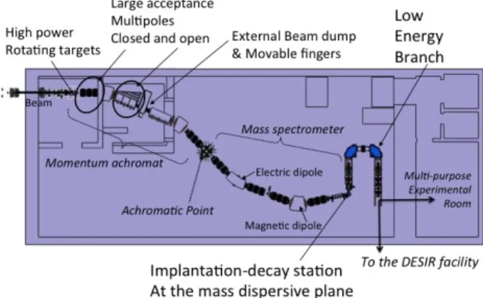
The basic design of S3 (Figure 1) involves the
following main equipment:
- An upstream beam line leading to rotating targets that can sustain the high power beams either on stable or radioactive actinides.
- The Separator-Spectrometer itself, with high transmission and high resolving power in two stages using a combination of magnetic and electric dipoles with large aperture multipole triplets. First, a momentum achromat collects most of the interesting reaction products and extracts most of the high intensity beam in a specific dump area. Second, a mass spectrometer further purifies the transmitted nuclei and allows for their mass measurement
- A standard detection system dedicated to implantation-decay experiments, for decay spectroscopy (e-, p, α, γ) of the interesting nuclei.
- Alternatively to this detection system, a low energy branch, with a high current gas catcher and subsequent RFQ accelerator, coupled to a ultra high resolution spectrometer in order to measure ground state properties of nuclei with an appropriate detection system (β-decay station, ion trap, chemistry apparatus, etc.) or, in future, to transmit the purified low emittance beam to the DESIR facility.
Fig. 1. Basic Layout of S3 with the low energy branch.
3.1. Target system
The roughly three meters of space between the last primary beam focusing quadrupole (before the production target) and the first multipole of S3 will be principally
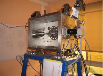
occupied by beam diagnostic detectors, steering and beam raster dipoles, fast-acting vacuum isolation valves and the rotating target box. Two target stations are foreseen. The first is a large (36cm radius) wheel supporting targets made of stable materials, with a rotation speed above 2000rpm. The second is a smaller (8cm radius) wheel that can host actinide targets and can rotate up to 5000rpm. A prototype is currently being tested at GANIL (Figure 2). Targets’ integrity is
continuously monitored by various diagnostics, notably an electron gun.
Fig. 2. Prototype of the actinide target station.
3.2 Separator-Spectrometer
S3 is a two-stage system. The first stage is a magnetic
momentum achromat, which allows the separation of the primary beam from the recoil products. It is followed by a mass separator, which includes an electrostatic dipole and a magnetic dipole for mass selection.
In the magnetic momentum achromat, the different charge states of the primary beam follow different trajectories after the first magnetic dipole. Some of them are no longer within the system acceptance and would normally hit the following multipole magnets; this situation has to be avoided. To enable primary beam extraction, these magnets have to be opened on one side, which requires a specific, original design of room temperature magnets with superimposed quadrupole and sextupole fields.
The needed characteristics of S3 and the ion optical
simulations have led to dedicated multipole designs (for 21 closed multipoles and 3 open multipoles). In order to meet the requirements of the optics, the multipole magnets must have a large aperture of 300 mm diameter and embedded quadrupole, sextupole and octupole coils. For this purpose, we are currently designing closed superconducting magnets that are able to provide superimposed quadrupole, sextupole and octupole fields.
Fig. 3. Picture of the open magnets.
3.3 Beam dump system
The magnetic triplet following the first dipole is “open” so that the high-power beam dump can be located outside the multipole magnets in a shielded area; when required (e.g. if a manned maintenance is required in the beam dump area), the beam dump elements can be completely isolated by movable lead shielding. The beam dump is made of fixed and multi-finger movable stopping parts (to be placed according to the specific experiment running) and includes also fixed and movable shielding for secondary radiation from these elements. A static plate—the high magnetic rigidity beam dump—receives most of the beam intensity for most experimental cases. When some populated beam charge states are within the acceptance of the spectrometer, adjustable fingers can be placed to block these spatially localized charge states while stopping only a small part of the nuclei of interest.
3.4 Standard detection system
The “standard” detection of the spectrometer is an implantation-decay station (see Figure 4). It should be position sensitive, both for the measurement of mass, when placed at the spectrometer focal plane, and for the spatial correlation of implantation-decay sequences. Energy and time of flight measurements are required for a better selection of the nuclei and for charged particle spectroscopy. Coincident gamma-ray spectroscopy is also required and can provide additional selectivity in some cases.
These properties are obtained by a combination of several detectors: emissive foil tracking detectors (measuring trajectories and time of flight), implantation double sided stripped silicon detector (energy and time measurement as well as space-time correlation), “Tunnel” silicon detector (detection of charged particle decays: alphas, protons and electrons) and germanium detectors for gamma spectroscopy. The active area of the focal plane implantation detectors is 10x10cm2.
Fig. 4. Schema of the detection set-up.
3.5 Low energy branch
For the wide range of measurements of ground state properties, S3 must be connected to a low-energy branch.
This branch includes: a gas catcher that stops the ions at the end of the spectrometer and a low energy beam line
EPJ Web of Conferences
that reaccelerates the ions up to 40keV and transports them to a secondary detection set-up. In cases where laser spectroscopy can advantageously be done directly at the source, the initial gas catcher could be replaced by the KU Leuven laser ion source, which is element selective and allows LIST laser spectroscopy measurements on exotic isotopes. The purified ions will then be transported by the low-energy branch to various detection systems, such as an ion trap for collinear laser spectroscopy, a penning trap for mass measurement, a beta-NMR station or a chemistry set-up.
The DESIR facility, also planned to be installed at SPIRAL2, will have most of these instruments. The connection between DESIR and S3 will provide an
exceptional array of possibilities to study the ground state properties of radioactive ions that are difficult to produce by the ISOL method such as heavy and superheavy or refractory elements. For some specific applications, it is also possible to install a detection set-up in the multi-purpose, low-energy experimental room of S3.
4 Optics & performances
The first standard optical mode of S3 is a high mass
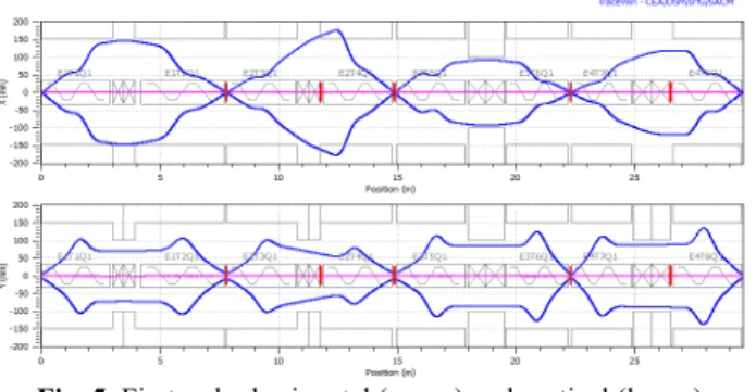
resolution mode. Optics optimization is done in two steps with the Tracewin [4] software. Additional details can be found in [3]. For both the momentum achromat and the mass spectrometer the quadrupoles are tuned in first order to obtain a given (momentum or mass) resolution at in intermediate dispersive plane and an achromatic point at the end (Figure 5). All the triplets have the same polarity (focussing-defocussing-focussing in horizontal). All the distances take into account the encumbrance of all the required equipment (steerers, beam profilers, valves, etc.). Then the sextupoles are optimized in order to maximize the mass resolution, with a full ray-tracing simulation of the spectrometer. Realistic 3D field maps represent all the magnets, except the dipoles that use an analytical model. In that configuration, the angular acceptance is ±50mrad in vertical and -50/+40mrad in horizontal, with aberrations observed for increasing angles (Figure 6, left).
Fig. 5. First order horizontal (upper) and vertical (lower)
envelopes with standard optics.
Using this tuning with the reaction products from 58Ti + 46Ti → 100Sn + 4n, with σ
θ=20mrad gives a transmission
of 56%. Since four charge states of the primary beam are within the momentum acceptance of the system, fingers
must be used in this case. Fingers 1cm wide reduce the transmission of 100Sn to 46%. Five charge states of 100Sn
are transmitted to the final m/q dispersive focal plane. The average mass resolving power is 379 (FWHM). For very large emittance reactions, a different optical mode is proposed. In this mode, the vertical acceptance goes to ±70mrad and the horizontal to -70/+40mrad (figure 4, right). For the reaction 22Ne+238U → 255No + 5n,
which has a very broad angular distribution (σθ=70mrad)
the transmission is then 15%. Two charge states of the beam must be blocked with fingers. In order to most powerfully reduce primary beam scattering, large fingers of 3cm width (equivalent to ±10σ of the primary beam spot width) can be used. This reduces the transmission of
255No to 10%. Only two charge states of 255No are
transmitted, since the populated charge states are very low (only 8+). The mass resolving power is also reduced for this case to 170, since aberrations grow with the larger transmitted emittance. This resolution is no longer sufficient to discriminate between evaporation channels, but is enough to separate target-like ions. The evaporation residues are then identified by their spectroscopic properties.
Fig 6. Horizontal and vertical acceptances in the high resolution
mode (left) and high acceptance mode (right).
This work was partially supported by the U.S. Department of Energy, Office of Nuclear Physics, under Contract No. DE-AC02-06CH11357 and by the E.C. FP7-INFRASTRUCTURES- 2007, SPIRAL2 Preparatory Phase, Grant agreement No.: 212692. We greatly thank A. Popeko (JINT, Dubna) for discussions and advice on the secondary particle distributions.
References
1. A. Drouart & al., Int Jour of Mod Phys. E, 18 2160 (2009)
2.
http://pro.ganil- spiral2.eu/spiral2/instrumentation/s3/working-documents/loi-day-1-experiments
3. D. Boutin & al., International Particle Accelerator
Conference (IPAC 2010), Kyoto : Japon, 4464
(2010)
4. D. Uriot, TraceWin code:
http://irfu.cea.fr/Sacm/logiciels/index3.php