HAL Id: hal-01073884
https://hal.archives-ouvertes.fr/hal-01073884
Submitted on 10 Oct 2014
HAL is a multi-disciplinary open access
archive for the deposit and dissemination of
sci-entific research documents, whether they are
pub-lished or not. The documents may come from
teaching and research institutions in France or
abroad, or from public or private research centers.
L’archive ouverte pluridisciplinaire HAL, est
destinée au dépôt et à la diffusion de documents
scientifiques de niveau recherche, publiés ou non,
émanant des établissements d’enseignement et de
recherche français ou étrangers, des laboratoires
publics ou privés.
Synthesis and characterization of La2NiO4+δ coatings
deposited by reactive magnetron sputtering using
plasma emission monitoring
Jérémie Fondard, Alain Billard, Ghislaine Bertrand, Pascal Briois
To cite this version:
Jérémie Fondard, Alain Billard, Ghislaine Bertrand, Pascal Briois. Synthesis and characterization of
La2NiO4+δ coatings deposited by reactive magnetron sputtering using plasma emission monitoring.
Solid State Ionics, Elsevier, 2014, vol. 265, pp. 73-79. �10.1016/j.ssi.2014.07.017�. �hal-01073884�
To link to this article :
doi:10.1016/j.ssi.2014.07.017
URL :
http://dx.doi.org/10.1016/j.ssi.2014.07.017
O
pen
A
rchive
T
OULOUSE
A
rchive
O
uverte (
OATAO
)
OATAO is an open access repository that collects the work of Toulouse researchers and
makes it freely available over the web where possible.
This is an author-deposited version published in :
http://oatao.univ-toulouse.fr/
Eprints ID : 12091
To cite this version :
Fondard, Jérémie and Billard, Alain and
Bertrand, Ghislaine and Briois, Pascal Synthesis and
characterization of La2NiO4+δ coatings deposited by reactive
magnetron sputtering using plasma emission monitoring. (2014)
Solid State Ionics, vol. 265 . pp. 73-79. ISSN 0167-2738
Any correspondance concerning this service should be sent to the repository
administrator:
staff-oatao@listes-diff.inp-toulouse.fr
Synthesis and characterization of La
2
NiO
4 + δ
coatings deposited by
reactive magnetron sputtering using plasma emission monitoring
J. Fondard
a,b,⁎
, A. Billard
a,b, G. Bertrand
c, P. Briois
a,baIRTES-LERMPS, EA 7274, 90010 Belfort, France bFR FCLab 3539, 90000 Belfort, France
cCIRIMAT UMR5085, INPT-ENSIACET, 4 allée E. Monso, BP 44362, 31030 Toulouse Cedex 4, France
a b s t r a c t
Keywords: La2NiO4
Reactive magnetron sputtering Plasma emission monitoring Structural investigation Electrical properties
This work focuses on the structural and electrical characterization of La–Ni–O coatings deposited by reactive magnetron sputtering using Plasma Emission Monitoring (PEM) which allows high deposition rate. The optimal regulation setpoint for lanthanum deposition is determined and then the current dissipated on the nickel target is adjusted to obtain the convenient La/Ni ratio to achieve the K2NiF4structure. After an appropriate annealing
treatment, all coatings exhibit crystalline structures that depend on the La/Ni ratio. Some cracks appear on sam-ples deposited on alumina substrates depending to the argon flow rate and influence their electrical behavior.
1. Introduction
It is well known that the short life time and the high cost of the components of nowadays Solid Oxide Fuel Cells (SOFC) are induced by their high operating temperature (1273 K). The challenge, that many researches try to face with, is to reduce this operating temper-ature below 1073 K while maintaining the fuel cell performances (IT-SOFC). However at low operating temperature, the electrocatalytic activity of the standard cathode (lanthanum strontium oxide such as LSM: La1 − xSrxMnO3) decreases, leading to high overpotential and reduced power density. These lanthanum strontium oxides have also been involved in the formation of secondary phases at the interface with the YSZ electrolyte (La2Zr2O7or SrZrO3) leading to degradation in cell performance. So there is a need to develop new cathode materials that will operate at low temperature with high reliability and chemical stability. Amongst others, A2MO4 + δ compounds with K2NiF4structure have recently been investigated as promising substitutes for LSM. Indeed, these materials are mixed ionic and electronic conductors (MIECs) that moreover exhibit rath-er high electrocatalytic proprath-erties. It could then be attempted to syn-thesize them as dense materials for SOFC cathodes. A specific
attention was focused on lanthanum nickelate La2NiO4 + δbecause it exhibits convenient electrochemical characteristics[1–5]. Its thermal expansion coefficient (TEC) is very close to those of the most commonly used electrolyte materials (13 · 10− 6K− 1[2], 11.9·10− 6K− 1and 11.6·10− 6K− 1for La
2NiO4 + δ, CeO2–Gd2O3(CGO) and ZrO2–Y2O3 (YSZ) respectively). Moreover, its TEC value is very close to the one re-corded for ferritic steel interconnect materials (11.0–12.5·10−6K−1) [9]which are essential in the last generation metal supported SOFC stack. Its oxygen surface exchange coefficient (k) and oxygen diffusion coefficient (D*) are interesting and seem much better than those of LSM and La1 − xSrxCo1 − yFeyO3(LSCF), the most commonly used cathodes (Table 1).
La2NiO4coatings have already been produced in our laboratory implementing conventional reactive magnetron sputtering[10]. In this study, we investigate the feasibility of producing thin and dense La2NiO4+ δcoatings as performed in the literature[11–13]by reactive magnetron sputtering under unstable conditions using Plasma Emission Monitoring (PEM)[14,15]. This technique is assumed to allow the depo-sition of oxide coatings with high sputtering rate. Four point probe elec-trical analyses were performed on annealed lanthanum nickelate films in static air at room temperature and in the temperature range from 293 to 1273 K every 25 K. On the one hand, measurements were carried out after 60 min stabilization in order to follow the effect of the as-deposited sample crystallization. On the other hand, the electrical con-ductivity is followed after 20 min stabilization for K2NiF4structure's samples.
⁎ Corresponding author at: IRTES-LERMPS, EA 7274, 90010 Belfort, France. Tel.: +33 384 583 730; fax: +33 384 583 737.
E-mail address:jeremie.fondard@utbm.fr(J. Fondard).
2. Experimental details 2.1. Deposition device
The experimental deposition device is a 100 L Alcatel SCM 650 sputtering chamber pumped down via a system combining XDS35i Dry Pump and a 5401CP turbo-molecular pump. The sputtering cham-ber is equipped with three 200 mm in diameter magnetron targets and with a 620 mm in diameter rotating substrate holder parallel to the targets at a distance of about 110 mm. The La and Ni targets were supplied with a pulsed DC Advanced Energy dual generator allowing the control of the discharge current. The discharge current was fixed at 2.5 A on the La target and was varied on the Ni target to obtain the convenient composition of the K2NiF4structure. The substrates were made of alumina and YSZ pellets as well as glass slides positioned on the substrate holder at 170 mm from its center point. Argon and oxygen flow rates were controlled with Brooks flowmeters and the pressure was measured using a MKS Baratron gauge. The deposition stage was monitored using a closed loop control PEM (Plasma Emission Monitor-ing) system relying on an optical emission spectroscopy device (OES) [15,16]. This technique is based on the measurement of the optical in-tensity of the 394.91 nm La emission line (ILa⁎) emitted from a volume near the target. The signal is collected through an optical fiber and di-rected to a Ropper Scientific SpectraPro 500i spectrometer, with a 1200 groove mm− 2grating and a photomultiplier tube (Hamamatsu R 636). Then, the information is transferred to a computer where a homemade software developed with Labview® monitors the oxygen flow rate to maintain the intensity of the optical signal ILa⁎ at a fixed value.
2.2. Structural, morphological and optical characterizations
The morphology of the coatings was characterized by Scanning Elec-tron Microscopy (SEM) using a JEOL JSM 5800 LV equipped with Energy Dispersive Spectroscopy (EDS) for chemical measurements. The struc-tural features of the coatings were identified in Bragg–Brentano config-uration X-ray diffraction using a BRUKER D8 focus diffractometer (CoKα1 + α2radiations) equipped with the LynxEye linear detector. XRD patterns were collected at room temperature during 10 min in the [20°–80°] scattering angle range by steps of 0.019°. The coating thickness was determined using the “step” method (a small surface of the sub-strate is covered with a tape that is removed after deposition leaving a step due to the coating thickness) with an Altysurf profilometer from Altimet allowing an accuracy of about 20 nm. Before each measurement, the calibration of the experimental device was realized with a reference sample number 787569 accredited by CETIM, France.
The optical transmittance measurements were performed with a UV–visible-NIR Shimadzu UV-3600 Spectrophotometer controlled by UV probe 2.33 software. All measurements were carried out on glass substrates between 380 and 780 nm.
2.3. Electrical measurements
The electrical resistivity measurements were performed with a HP 3458A multimeter on La–Ni–O films deposited on alumina substrates. With regard to its high insulating character, it is assumed in the follow-ing that the substrate has no significant contribution to the electrical conductivity. The four-point-probe technique with four Pt aligned elec-trodes was used. Two outer probes behaved as the current-carrying electrodes (I1, I2) and the two inner ones were used to measure the voltage (E1, E2). Two cell configurations were used for the measure-ments: cell 1 was used to define the resistivity at room temperature (Jandel, Linslade, UK). It is a standard and certified cell allowing the ac-curate determination of the geometric factor. The second cell developed by the LEPMI laboratory (Grenoble, France) allows measurements at various temperatures. The cell is placed inside an alumina tube and po-sitioned into a furnace (Pekly, Thions Gardais, France). The comparison of the resistance measured at room temperature with cell 1 and cell 2 was used to determine the geometric factor of cell 2.
Table 1
Surface exchange (k) and oxygen diffusion coefficients (D*) for different cathode materials. D* (700 °C) k (700 °C) La2NiO4 3.4 · 10−8[2], 1.6 · 10−8[6], 5.0 · 10−8[7] 1.7 · 10−7[2], 1.3 · 10−7[6], 2.0 · 10−6[7] LSM 3.2 · 10−16[8] 1.0 · 10−9[8] LSCF 3.2 · 10−9[7], 7.2 · 10−9[8] 1.0 · 10−7[7], 6.1 · 10−7[8]
3. Result and discussion
3.1. Determination of the optimal regulation setpoint
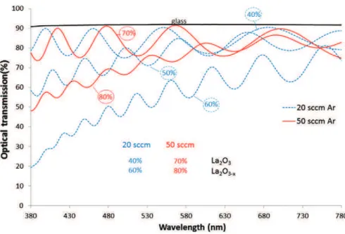
In DC or pulsed DC mode, the optical signal of the sputtered metal atoms IM⁎ measured by OES in a pure Ar atmosphere varies as the square function of the discharge current[18,19]. When oxygen gas is intro-duced into the discharge, a hysteresis loop appears on the oxygen par-tial pressure versus oxygen flow rate curve related to the instability of the sputtering conditions. So, the transition between the fast metallic and the slow ceramic deposition rates occurs suddenly. The Plasma Emission Monitoring (PEM) system allows the deposition of oxide coat-ings in these unstable sputtering conditions by fixing the intensity of the plasma emission line of the metallic atoms sputtered from the target with a closed loop as previously detailed in[14]. Indeed, PEM is a very suitable technique to allow high growth rate of oxide coatings[14,20]. As the main element of La2NiO4is La, the PEM control was performed on the La target at a fixed 2.5 A discharge current in order to deposit coatings with high sputtering rate without consuming too much the tar-get. In the first set of experiments, the optical emission signal collected in pure argon atmosphere was allocated to 100%. Then, the PEM setpoint ILa⁎ was varied from 30 to 80% in order to deposit transparent coatings.
Fig. 1shows the evolution of the optical transmission of La–O coat-ings deposited at 2.5 A applied on the La target for various Ar flow rates and regulation setpoints. For coatings deposited with 20 sccm Ar flow rate, a regulation setpoint fixed at 40% produces an unattenuated optical signal, which reveals the transparency (low extinction coeffi-cient k) of the coating. The optical signal value is between 75 and 90%, the latter value is similar to the one recorded for glass. Moreover, the optical transmission signal is more and more attenuated for higher setpoints. In a previous study dedicated to the optical emission spec-troscopy study of the deposition of TiO2[16], it was shown that increas-ing the setpoint decreases the coatincreas-ing transparency and then the stoichiometry of the coating. Indeed, the sputtered flow of metal atoms increases with the setpoint, which was associated with a reduc-tion of the oxygen partial pressure in the reactor. Higher Ar flow rate in-duces higher total pressure in the device and then theoretically less dense and more columnar coatings with lower deposition rate. Such be-havior means that the La–O based film is fully oxidized for setpoints lower than 40% and sub-stoichiometric for higher setpoints. Indeed, as
shown by Briois et al. for YSZ coatings characterized by spectrophotom-etry and EPMA, transparent coatings are fully oxidized[21]. By increas-ing the Ar flow rate at 50 sccm, the transition between stoichiometric and under-stoichiometric oxide deposits appears at higher setpoints (i.e. 70%). The choice of the optimal setpoint must also be guided by the deposition rate of the coatings.Fig. 2shows that the deposition rate is varying linearly with the setpoint values. A deposition rate around 0.65 μm/h is achieved at a setpoint of 30% whatever the Ar flow rate whereas if the setpoint is doubled it is of 1.6 and 0.9 μm/h for 20 and 50 sccm, respectively. By increasing the Ar flow rate, the de-position rate becomes less sensitive to the variation of the regulation setpoint. A setpoint of 50% was then chosen for the 20 sccm Ar flow rate flow rate because it presents a good compromise between deposi-tion rate and stoichiometry of the coating. In addideposi-tion, the difference be-tween the atomic radii of La (187 pm) and Ni atoms (124 pm) would probably lead during the deposition of the cathode layer to an amor-phous coating because of the confusion principle. This phenomenon im-poses the realization of a crystallization annealing treatment which may saturate the film. For higher Ar flow rate (i.e. 50 sccm), the differences between the deposition rates at 70% and 80% are not significant enough. So the coatings will be deposited with the conditions allowing the depo-sition of a transparent coating (i.e. 70% setpoint).
3.2. Elaboration of La–Ni–O coatings
The experimental parameters for the synthesis of the films are sum-marized inTable 2. The coatings are deposited by the co-sputtering of La and Ni targets in Ar–O2mixtures for which the oxygen flow rate is con-trolled by the PEM system.Fig. 3presents the metallic La/Ni ratio
Fig. 2. Deposition rate of La2O3coatings as a function of I⁎Lafor 20 and 50 sccm Ar.
Table 2
Main deposition conditions of the study.
Ar flow rate = 20 sccm Ar flow rate = 50 sccm
Total pressure (Pa) 0.30 0.44
Setpoint (%) 50 70
Oxygen flow rate (sccm) 5.5–6.2 4.5–4.9 Run duration (h) 1 h 30 min–2 h 2 h–2 h 20 min Discharge current for La (A) 2.5 2.5 Frequency (Hz) — toff (μs) 50–5 50–5 Discharge current for Ni (A) 0.25–0.45 0.55–0.65 Frequency (Hz) — toff (μs) 50–5 50–5
determined by EDS analyses versus the discharge current applied to the Ni target while the La target current is fixed at 2.5 A. EDS measurement is sufficiently accurate to determine the cationic composition of thin films because this technique is well adapted to measure heavy elements as shown elsewhere[21]. For both Ar flow rates, the metallic ratio de-creases linearly with the increase of the current. In addition, a higher current is needed to deposit the same metallic ratio at high Ar flow rate. To obtain the La2NiO4composition a current discharge of 0.3 and 0.57 A with 20 and 50 sccm Ar flow rates (1.94 and 2.04 La/Ni ratio) must be supplied, respectively. The linear evolution of the composition with the current applied on the Ni target reveals that the oxygen flow
rate is sufficient to deposit a ceramic instead of a metallic layer. The reg-ulation ensures then a constant oxidation rate of the La target and sub-sequently a constant sputtering rate of the La atoms. As expected, XRD performed on as-deposited samples shows the presence of an amor-phous structure whatever the composition. In order to crystallize the La2NiO4phase, different annealing temperatures (973 K–1273 K for 2 h) were tested in a previous study[22]with samples presenting that a La/Ni ratio of about 2. 1173 K for 2 h was found to be the optimal ther-mal treatment. It has to be noticed that these coatings are annealed at higher temperature than those deposited with stable sputtering condi-tions [10].Fig. 4 presents the XRD patterns of annealed coatings
Fig. 3. Evolution of atomic composition ratio La/Ni measured by EDS as a function of current dissipated on the Ni target for different Ar flow rates ( ILa= 2.5 A).
Fig. 4. XRD spectra as a function of La/Ni metallic ratio for 20 sccm and 50 sccm Ar flow rates after annealing at 1173 K for 2 h. JCPDS files: 00-033-0710, 00-050-0243, 071-1126, 01-083-1344, 01-089-3460.
elaborated at 20 (Fig. 4a) and 50 sccm (Fig. 4b) of Ar flow rates and var-ious discharge currents, which means varvar-ious atomic La/Ni ratios. The crystalline structure of the La–Ni–O coatings evolves with the metallic ratios. When the Ni content is high (La/Ni ratio below 1.5, seeFig. 4b), coatings crystallize mainly in the LaNiO3structure. By decreasing the Ni content (La/Ni ratio between 1.5 and 2), a mixture of phases is iden-tified that includes LaNiO3, La4Ni3O10and La2NiO4. La2NiO4is the only phase identified for the coatings elaborated with ratios around 2 (1.91 and 1.94 at 20 sccm 2.04 and 2.17 at 50 sccm). For a La/Ni ratio superior to 2, the diffraction peaks are moved to the lowest angles, implying an increase of the lattice parameter due to an excess of La in which atomic radius is bigger than the Ni one. When La2NiO4phase is oxygen saturat-ed, La2O3is crystallizing. These results are in agreement with the La–Ni– O phase diagram in air[23]. Same behavior is noticed for both Ar flow
rates studied in this work. However, increasing the Ar flow rate seems to enhance the crystallization but the coating appears to be oriented along the (113) crystallographic plane.
Morphological features were observed by SEM on the surfaces of the coatings (Fig. 5) and on the brittle-fracture cross sections (Fig. 6) of as-deposited and annealed coatings. The observation of the sur-face of the as-deposited films (Fig. 5a and c) reveals an adherent and covering film with a top morphology reproducing that of the alumi-na substrate. These coatings are then conformal. This observation is confirmed by the arithmetic roughness measurements (Ra) of the sam-ples before and after deposits which are 0.49 ± 0.01 μm and 0.51 ± 0.01 μm respectively. The good adherence of these films is pointed out by the observation of the cross section of the films (Fig. 6) which also denotes a slightly columnar aspect. The thickness of these films is in
Fig. 5. SEM view of surface of samples deposited on alumina substrate with 20 sccm (a, b) and 50 sccm (c, d) Ar as-deposited (a, c) and annealed in air for 2 h at 1173 K (b, d) with La2NiO4
structure. View of a coating deposited at 50 sccm Ar on YSZ after annealing (e).
Fig. 6. Brittle fracture cross section of samples deposited with 20 sccm (a, b) and 50 sccm (c, d) Ar on alumina substrate as-deposited and annealed in air for 2 h at 1173 K with La2NiO4
good agreement with 3D measurements (i.e. ≈3.5 μm). The crystalliza-tion thermal treatment allows the densificacrystalliza-tion of the coatings (Fig. 6b and d) but some cracks appear on the surface (Fig. 5b and d). These cracks are more visible on the films deposited with an Ar flow rate of 20 sccm (Fig. 5b) than 50 sccm (Fig. 5d). Indeed, a lower pressure causes a higher coating density, which increases the mechanical strains due to the different thermal expansion coefficients between the film and the substrate during the annealing treatment at high temperature. Alumina TEC is much lower than the coating one, 7 and 13 · 10−6K−1 respectively. Cracking of films could then happen during cooling. In order to check this hypothesis, films were synthesized on YSZ sub-strates (conventional material of SOFC electrolytes) in which TEC is around 11 · 10−6K−1, closest to the coating one as compared to alumi-na. The surface and cross section observations after the thermal treat-ment for the coatings realized with Ar flow rate of 50 sccm show no cracks, which is favorable for the SOFC materials commonly used (Figs. 5e and6e).
3.3. Electrical analyses
In order to assess the effect of the crystallization on the sample con-ductivities, electrical measurements were performed implementing a four point probe method on as-deposited samples presenting a metallic ratio of about 2 as reported inFig. 7. Changes in the resistance versus temperature curve slopes are clearly identified on this graph and in-volve structural, microstructural or chemical modifications of the films. The correlation with XRD measurements performed on the sam-ples deposited with 50 sccm Ar after annealing at increasing tempera-tures[22]shows that amorphous coatings are highly resistive and that the coating resistance decreases with its crystallization. During the in-crease in temperature, different crystallographic phases appear. La2O3 and La4Ni3O10orthorombic phases are the first phases to crystallize. La2NiO4tetragonal phase starts to crystallize from 1123 K[22]. More-over, the crystallization seems to occur at lower temperature for the sample deposited with 50 sccm of Ar flow rate.
In order to determine the characteristics of the well-crystallized films, samples were annealed at 1173 K for 2 h under air before performing the electrical measurements. The resistivity of the annealed coatings as a function of their La/Ni ratio at room temperature (286 K) and after 20 min stabilization at 973 K is reported inTable 3. The in-crease of the Ni content in the samples permits to obtain the highest
conductivities. As expected, the most favorable behavior is obtained for the samples which crystallized mainly as a perovskite LaNiO3 struc-ture. However the La2NiO4structure presents reasonable conductivities. For the same metallic ratios and also the same structure (La/Ni = 1.69– 1.75 and 1.95–2.04), the electrical conductivity of the samples deposited with 50 sccm Ar is higher than with 20 sccm at 973 K. This difference is certainly due to the presence of cracks on the surface of the samples de-posited with 20 sccm Ar. There is probably no effect of the density of the coatings because the four point probe technique takes place only on the surface of the samples and not through its thickness.
Samples with a La/Ni ratio of about 2, which means a La2NiO4 struc-ture after annealing 2 h at 1173 K, were especially studied from 293 to 1273 K after 20 min stabilization at each temperature (Fig. 8). The con-ductivity of these samples increases with temperature and tends to be stabilized over 773 K. The electrical behavior of the corresponding bulk materials is quite different. The conductivity of these samples in-creases up to a temperature around 773 K and dein-creases at higher tem-peratures. This diminution is explained by an oxygen loss in the structure of the bulk materials[2,3,17]. Consequently, it could be as-sumed that oxygen stoichiometry of thin layers seems to be less sensi-tive to temperature.Fig. 8highlights that the electrical conductivity of the films (30–60 S·cm) is in the same order of magnitude than the one of bulk materials in SOFC application domain. As explained before, samples deposited with 20 sccm and 50 sccm Ar flow rates present dif-ferent conductivities certainly induced by the presence of cracks but their different crystallographic orientations may also assume a role in their electrical behavior. Electrical tests were also repeated for several cycles during the heating and the cooling stages of the sample deposited
Fig. 7. Resistance of as deposited coatings of La2NiO4composition deposited with 20 sccm (La:Ni = 1.94) or 50 sccm Ar (La/Ni = 2.04) as a function of the annealing temperature.
Table 3
Resistivity of La–Ni–O crystallized samples with different Ar flow rates. Ar flow rate Samples' conductivity at room temperature and at
700 °C (S·cm) La/Ni ratio 1.25 1.41 1.57 1.69 1.75 1.95 2.04 2.32 2.49 20 sccm 293 K 275.5 116.2 10.9 2.3 0.01 973 K 295.0 157.7 45.4 43.5 27.5 50 sccm 293 K 144.0 16.2 2.2 0.06 973 K 292.3 62.3 52.2 22.1
with 50 sccm Ar flow rate. All the tests showed the same electrical be-havior with quite the same electrical conductivity values.
5. Conclusion
La–Ni–O coatings were deposited by magnetron sputtering on different substrates by co-sputtering of La and Ni metallic targets in the presence of reactive argon–oxygen mixture gas. The use of a closed loop control which consists of controlling the introduced re-active gas flow rate in order to fix the system in unstable sputtering domain allows obtaining optimal deposition rates under chosen op-erational conditions. As-deposited coatings with La/Ni ratios of about 2 are amorphous and crystallize under a tetragonal La2NiO4 phase after an annealing treatment at 1173 K for 2 h under air. A higher Ar flow rate, i.e. a higher pressure, coupled with a lower setpoint allows minimizing the crack formation during the treat-ments and leading thus to a higher electrical conductivity. La2NiO4 coatings present an electrical conductivity of 30–60 S·cm in the tem-perature range for intermediate temtem-perature solid oxide fuel cells (873–1073 K). These values are in the same order of magnitude than the values reported for bulk samples in the literature.
Acknowledgments
The authors thank the Pays de Montbéliard Agglomeration for their financial support during this study.
References
[1] V.V. Vashook, I.I. Yushkevich, L.V. Kokhanovsky, L.V. Makhnach, S.P. Tolochko, I.F. Kononyuk, H. Ullmann, H. Altenburg, Solid State Ionics 119 (1999) 23–30.
[2] E. Boehm, J.-M. Bassat, P. Dordor, F. Mauvy, J.-C. Grenier, Ph. Stevens, Solid State Ionics 176 (2005) 2717–2725.
[3] V.V. Kharton, E.V. Tsipis, E.N. Naumovich, A. Thursfield, M.V. Patrakee, V.A. Kolotygin, J.C. Waerenborgh, I.S. Metcalfe, J. Solid State Chem. 181 (2008) 1425–1433.
[4] A.L. Shaula, E.N. Naumovich, A.P. Viskup, V.V. Pankov, A.V. Kovalevsky, V.V. Kharton, Solid State Ionics 180 (2009) 812–816.
[5] J. Dailly, S. Fourcade, A. Largeteau, F. Mauvy, J.C. Grenier, M. Marrony, Electrochim. Acta 55 (2010) 5847–5853.
[6] R. Sayers, R.A. De Souza, J.A. Kilner, S.J. Skinner, Solid State Ionics 181 (2010) 386–391.
[7] H. Zhao, F. Mauvy, C. Lalanne, J.-M. Bassat, S. Fourcade, J.-C. Grenier, Solid State Ionics 179 (2008) 2000–2005.
[8] B.C.H. Steele, K.M. Hori, S. Uchino, Solid State Ionics 135 (2000) 445–450.
[9] J. Wu, X. Liu, J. Mater. Sci. Technol. 26 (4) (2010) 293–305.
[10] P. Briois, F. Perry, A. Billard, Thin Solid Films 516 (2008) 3282–3286.
[11]T. Mukai, S. Tsukui, K. Yoshida, M. Adachi, K. Goretta, Electrochem. Soc. Trans. 57 (2013) 1885–1891.
[12]H.-S. Noh, K.J. Yoon, B.-K. Kim, H.-J. Je, H.-W. Lee, J.-H. Lee, J.-W. Son, Electrochem. Soc. Trans. 57 (2013) 969–973.
[13]N. Hildebrand, B.A. Boukamp, P. Nammensma, D.H.A. Blank, Solid State Ionics 192 (2011) 12–15.
[14] A. Billard, C. Frantz, Surf. Coat. Technol. 59 (1993) 41–47.
[15] S. Schiller, G. Beister, W. Sieber, Thin Solid Films 111 (1984) 259–268.
[16] F. Perry, A. Billard, C. Frantz, Surf. Coat. Technol. 94–95 (1997) 681–685.
[17] G. Amow, I.J. Davidson, S.J. Skinner, Solid State Ionics 177 (2006) 1205–1210.
[18] F. Sanchette, T. Czerwiec, A. Billard, C. Frantz, Surf. Coat. Technol. 96 (2–3) (1997) 184–190.
[19] A. Billard, F. Perry, C. Frantz, Surf. Coat. Technol. 94-95 (1997) 345–351.
[20] P.-L. Coddet, M.C. Pera, A. Billard, Surf. Coat. Technol. 205 (2011) 3987–3991.
[21]P. Briois, F. Lapostolle, V. Demange, E. Djurado, A. Billard, Surf. Coat. Technol. 201 (2007) 6012–6018.
[22] J. Fondard, A.Billard, G.Bertrand, P.Briois, Proceeding of 5th International conference FDFC2013, P059, Structural and electrical characterization of K2NiF4 structure coat-ings deposited by magnetron sputtering.
[23] M. Zinkevich, F. Aldinger, J. Alloys Compd. 375 (1-2) (2004) 147–161.