OATAO is an open access repository that collects the work of Toulouse
researchers and makes it freely available over the web where possible
Any correspondence concerning this service should be sent
to the repository administrator: [email protected]
This is an author’s version published in: http://oatao.univ-toulouse.fr/27635
To cite this version:
Degeneve, Arthur and Vicquelin, Ronan and Mirat, Clément
and Caudal, Jean and Schuller, Thierry Impact of co- and
counter-swirl on flow recirculation and liftoff of non-premixed
oxy-flames above coaxial injectors. (2021) Proceedings of the
Combustion Institute, 38 (4). 5501-5508. ISSN 1540-7489.
Official URL:
https://doi.org/10.1016/j.proci.2020.06.279
Impact of co- and counter-swirl on flow recirculation and lifto
ff
of non-premixed
oxy-flames above coaxial injectors
A. Degenevea,b,∗, R. Vicquelina, C. Mirata, J. Caudalb, T. Schullera,c
aLaboratoire EM2C, CNRS, CentraleSup´elec, Universit´e Paris-Saclay, 3, rue Joliot Curie, 91192 Gif-sur-Yvette cedex, France bAir Liquide, Centre de recherche Paris Saclay, Chemin de la Porte des Loges, B.P. 126, 78354 Les Loges en Josas, France
cInstitut de M´ecanique des Fluides de Toulouse, IMFT, Universit´e de Toulouse, CNRS, Toulouse, France
Abstract
Controlling the flame shape and its liftoffheight is one of the main issues for oxy-flames to limit heat transfer to the solid componentsof the injector. An extensive experimental study is carried out to analyze the effects of co- and counter-swirl on the flow and flame patterns of non-premixed oxy-flames stabilized above a coaxial injector when both the inner fuel and the annular oxidizer streams are swirled.A swirl level greater than 0.6 in the annular oxidizer stream
is shown to yield compact oxy-flames with a strongcentral recirculation zonethat are attached to the rim of central fuel tube in absence of inner swirl. It is shown that counter-swirl in the fuel tube weakens this recirculation zone leading to more elongated flames, while co-swirl enhances it with more compact flames. These results obtained for high annular swirl levels contrast with previous observations made on gas turbine injectors operated at lower annular swirl levels in which central recirculation of the flow is mainly achieved with counter-rotating swirlers. Imparting a high inner swirl to the central fuel stream leads to lifted flames due to thepartialblockage of the flow at the injector outlet by thecentral recirculation zonethat causes high strain rates in the wake of the injector rim. Thispartialflow blockage is more influenced by the level of the inner swirl than its rotation direction. A global swirl number is then introduced to analyze the structure of the flow far from the burner outlet where swirl dissipation takes place when the jets mix. A model is derived for the global swirl numberwhich well reproducesthe evolution of the mass flow rate of recirculating gases measured in non-reacting conditions and the flame liftoff heightwhen the inner and outer swirl levels and the momentum flux ratio between the two streams are varied.
Keywords:
Co-/counter-rotating, Swirl, Oxy-combustion, Liftoff, Flame stabilization
Colloquium: Stationary System/ low Carbon Length of the paper determined using Method 2. Total length of the paper: less than 7.5 pages
The authors will pay color reproduction charges if ap-plicable.
∗
Corresponding author:
Email address: [email protected] (A. Degeneve)
Introduction
Conferring a rotational motion to the flow is widely used to extend the operational range of industrial injec-tors and increase flame compactness. A well-known ad-vantage of a swirled flow is the formation of a central recirculation zone (CRZ) above a swirl threshold level. The CRZ favors flame stabilization downstream the in-jector thanks to low velocities and recirculation of hot burned gases [1].
In non-premixed systems, swirl is also known to im-prove mixing between a fuel jet injected in the center of a swirled annular oxidizer stream [2–7]. Swirl can also be conferred to the central fuel stream [8–10]. Adding inner swirl was shown to help lifting CH4-air and H2
-air flames from the injector rim [8]. It was also used to control the liftoff height of C3H8-air flames [9]. In
these studies, the outer-to-inner momentum flux ratio between the two streams is small J 1. The way com-pact non-premixed swirled lifted flames could be stabi-lized above a coaxial injector was studied in [10] for a large range of momentum flux ratios 0.75 ≤ J ≤ 3, in-ner and outer swirl levels and mass fractions of O2 in
the annular oxidizer stream 0.23 ≤ YO2,2 ≤ 0.5. It was
shown that the inner S1and outer S2swirl numbers are
two independent parameters that can be tuned to adjust the flame liftoff height and flame shape. In these pre-vious studies, swirl in the central and annular streams is conferred in co-rotating direction. The present study aims at covering counter-rotating configurations to re-veal how the flow and flame structures are altered with respect to co-rotating operation.
Counter-swirl coaxial injectors are used in gas tur-bines operating in stratified premixed conditions [11– 14] or in rocket engines with non-premixed flames [15, 16]. Counter-swirl increases the shear stress in the wake of the central injector rim [11–14] which favors mixing and atomization when the inner stream is liquid fuel or liquid O2[15].
For moderate swirl levels S2 < 0.6 in the annular
stream, it was established that counter-swirl in the cen-tral stream S1enhances gas recirculation in the CRZ for
non-reacting jets [11–14]. Conversely, the CRZ disap-pears [12] or weakens [11, 14] when the same experi-ments are repeated without inner swirl S1 = 0 or with
an inner co-rotating swirler. Counter-swirl configura-tions therefore help the formation of a compact swirl-stabilized flame, when the inner S1 and outer swirl S2
levels are moderate [12]. Too large swirl levels lead to flashback or unacceptable pressure drop through the in-jector of gas turbines.
Many other industrial burners operate at a higher
swirl level S2 ∼ 1 in the annular channel and feature
a distinct behavior [17–19]. In these cases, a large CRZ prevails above the coaxial injector even in absence of inner swirl S1= 0. In co-rotating conditions, gas
recir-culation is enhanced and the CRZ is pushed further up-stream because the inner swirl reduces the penetration of the central jet in the CRZ [18, 19]. The same trends are reported in reacting conditions [17]. A co-rotating inner swirler leads to a better mixing between the cen-tral fuel stream, the annular oxidizer swirled stream and the recirculating burned gases [18]. More recently, a counter-rotating swirler was shown to alter the shape of the CRZ of highly swirled flames stabilized above a coal burner [20].
This short literature review highlights how the flow produced by co- and counter-rotating swirlers leads to opposite effects on flow recirculation when a coaxial in-jector is operated at a moderate S2< 0.6 or at a high
an-nular, say S2> 0.8, swirl number. These previous
stud-ies focus on a combustion region lying close to the injec-tion plane z/d1< 2,where z denotes the axial coordinate along the combustor centerline axis and d1the diameter
of the central fuel injector. Non-premixed flames are often anchored to the fuel nozzle rim z/d1 = 0, but in
many cases theymay also stabilizefurther downstream z/d1 > 6 [8–10]. Turbulent non-premixed methane/air
swirling flames are almost never attached to the injector rim at ambient conditions [21], but O2-enriched flames
exhibit a wider variety of topologies [10]. These two features have motivated this studyin whichthe impact of co- and counter-rotating swirl on the flame and flow patterns is characterized both at the outlet of the injector z/d1 = 0 and further downstream up to z/d1 = 15 with
the help of optical diagnostics.
1. Experimental setup
Experiments are carried out on the Oxytec combus-tor, already used to investigate scaling relations for the length of non-premixed swirling oxy-flames [7] and the effects of inner co-swirl on flame stabilization [10].
The combustion chamber represented in Fig. 1(a) has a square cross section. The injector sketched in Fig. 1(b) comprises a central tube of inner diameter d1 = 6 mm
and thickness e= 1 mmthat conveys the methane flow
and an annular channel of outer diameter d2 = 20 mm
filled with O2-enriched air.
Rotation is provided to both the central (1) and the annular (2) streams. Two swirl numbers Si, i= 1, 2, are
defined as Si = 2Gi,θ/(diGi,z), where Gi,θ and Gi,z are
the tangential and axial momentum fluxes in the axial direction. These fluxes are determined by integration of 2
Figure 1: Sketch of the combustor. (a) Schematic of the Oxytec test rig. (b) Axial cut of the coaxial injector. (c) Isometric view of the axial inner swirler. (d) Transverse cut through the annular swirler.
the axial uz and azimuthal uθ velocities over the cross
sections areas A1 and A2of the central tube and of the
annular channel: Gi,z = RA iρu
2
zdS is always positive,
whereas Gi,θ = RAiρruθuzdS is positive when uθ > 0
(counter-clockwise rotation), and negative when uθ< 0
(clockwise rotation).
The injection plane of the coaxial injector is located 5 mm above the back plane of the combustor to ease imaging the flame root and flame liftoff height. This in-jection plane defines the axial origin z = 0, and there is no recess between the central and the outer injection channel outlets. Four tangential slits generate a swirling motion, with swirl number S2, in the annular oxidizer
stream, as shown in Fig. 1(d). The distribution of the axial Q2,z and tangential Q2,θ volume flow rates
pro-vides an adjustable swirl level S2. Assuming a
solid-body rotation of the flow and a uniform axial velocity, the geometrical swirl number S2in the annular channel
is given by S2= Sm/(1+Q2,z/Q2,θ), where Sm= 1.23 is
deduced from geometrical considerationsas in [7]. The inner stream is swirled with the help of seven remov-able sets of axial twisted vanes with trailing edge angles θ1 = −60, -50, -30, 0, 30, 50 and 60◦, as illustrated in
Fig. 1(c). The central fuel and annular oxidizer streams are counter-rotating when θ1< 0 and co-rotating
other-wise. With the same hypotheses on the velocity profiles as in the annular channel, the geometrical swirl number S1in the central tube is given by S1= 1/2 tan(θ1).
The operating conditions covered in this study are re-ported inTable 1. The oxygen mass fraction is set to YO2,2 = 0.40 in the oxidizer stream as in [10]. This
oxygen concentration leads to a broad range of liftoff transitions and changes of flame topology.
Except for dataset D4, the momentum flux ratio J
between the annular (2) and central (1) streams is set to J = ρ2u2z,2/ρ1u2z,1 = 0.75, which is achieved by
fixing the axial velocity in the inner fuel stream to
uz,1 = 23.3 m.s−1 and the axial velocity in the annular oxidizer stream to uz,2 = 15 m.s−1. This sets the
ther-mal powerPth = 21.7 kW, the global equivalence ratio
φ = 0.91 and the annular flow in the turbulent regime with a Reynolds number Re2 = ρ2uz,2Dh/µ2 = 12, 000
based on the hydraulic diameter Dh= 12 mm. The swirl
number in the central fuel stream is systematically var-ied from S1 = −0.87 to 0.87. The swirl number in the
annular channel is initially fixed to S2= 0.85.
These conditions are used to investigate the structure of the flow with Particle Image Velocimetry (PIV) with liquid (datasetD1) and solid particles (datasetD2).The spatial resolution of the PIV measurements is δx = 0.6
and 1.2 mm for the non-reacting and reacting condi-tions, respectively. A sensitivity analysis, not shown here, has been carried out to verify that the velocity measurements and the position of the CRZ are left un-changed when slightly modifying the seeding of the flow and the duration time between the two laser im-pulses. For measurements in non-reacting conditions, the O2-enriched mixture is replaced by air, but the
in-ner stream is filled with methane to keep approximately the same gas density ratio as in reacting conditions. In reacting-conditions, PIV is synchronized with OH-PLIF measurements to track the unsteady position of the CRZ and the flame front (D2). The Q1(6) band of the
hy-droxyl radical is excited at λ = 282.93 nm with a laser delivering a 20 mJ energy pulse cadenced at 10 Hz. A full description of the optical diagnostics and image post-processing can be found in [22].
Abroaderset of flames (datasetD3andD4) has been
investigated with OH∗chemiluminescence to determine
the flame liftoff height zf with respect to the nozzle rim
when the inner swirl S1, the outer swirl S2and the
mo-mentum flux ratio J are parametrically varied.The OH∗ intensity is collected at the wavelength λ = 310 nm, and the recording time∆t = 30 ms is long compared to the largest turbulent time scales of the flow. Images are averaged over 100 snapshots. The Otsu thresholding method [23] is chosen to infer the flame front location from images [7, 24]. The flame liftoff height zf is
de-termined as the lowest point of the Otsu contour. The standard deviation of the liftoff height zf,rms is limited
Table 1: Operating conditions. All experiments are conducted with a fixed O2-fraction YO2,2=0.4 and a Reynolds number Re2=12, 000.
Set Diagnostic Conditions S1 S2 J
D1 PIV non-reac. ±0.87 0.85 0.75
D2 PIV/PLIF reac. ±0.87 0.85 0.75
D3 OH∗chem. reac. ±0.87 0.75 0.75
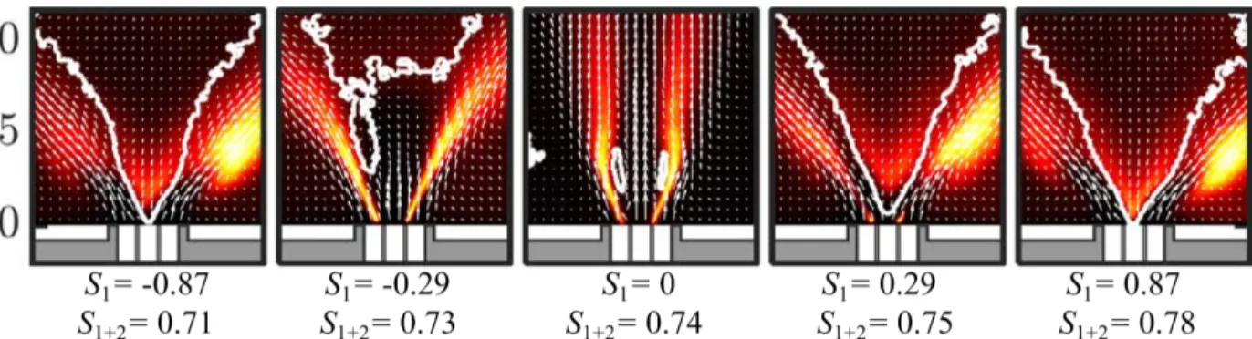
Figure 2: Mean axial velocity uzfor five coaxial jets in non-reacting conditions (D1dataset) for S2= 0.85, J = 0.75. S1is varied from −0.87 to
0.87.The recirculation zone is delineated by the thick white contour. to 10 % of its mean value zf. A sensitivity analysis has
been carried out to verify that the Otsu contour is left un-altered when the image brightness and contrast are var-ied. Finally, numerical simulations of one-dimensional flames have been performed to ensure that the tempera-ture and OH∗ peaks bothlie close to thereaction layer
at z= zst(see suplemental material in [7]).
2. Impact of S1on thenon-reactingflow
Impact of inner swirl on the structure of the non-reacting flow is investigated with PIV for five coax-ial jets (D1 dataset) at a fixed annular swirl number
S2 = 0.85 and momentum flux ratio J = 0.75. The
mean component of the axial velocity uzis shown in an
axial plane in Fig. 2. The azimuthal velocity profiles uθ
in a transverse plane are provided as supplemental ma-terial. The magnitude of S1and the swirl direction have
a considerable impact on the CRZ position delineated in white in Fig. 2. The location of the CRZ depends on the absolute value |S1| of the inner swirl number.
In theabsence of inner swirl S1 = 0, the central fuel
stream pushes the CRZ away from the injector. When |S1| increases, the CRZ moves upstream and establishes
closer to the injector outlet. Let Qr be the
recirculat-ing volume flow rate in the CRZat some fixed distance above the injector, Qr= −π R
r∗
−r∗uzrdr, where r
∗denotes
the radial coordinate where the axial velocity is zero: uz(−r∗) = uz(r∗) = 0. This flowrate isdetermined at
Table 2: Recirculating volume flow rate Qr divided by the injected
volume flow rate Q0 = 16.6 m3.h−1,ratio of tangential momentum
flux and global swirl number S1+2as a function of inner swirl S1for different heights z/d1above the injector. S2= 0.85. J = 0.75.
S1 z/d1 −0.87 −0.29 0 0.29 0.87 Qr/Q0(%) 1 4.4 1.4 0 5.0 5.8 Qr/Q0(%) 6 0 0.02 0.37 0.39 1.3 Gθ,1+2/GS1=0 θ,1+2 4 0.86 0.99 1.0 1.07 1.05 S1+2(Eq. 1) 0.71 0.73 0.74 0.75 0.78
the heights z/d1= 1 and 6, represented as white dashed
horizontallines in Fig. 2.Results are shown inTable 2. Results are first analyzed close to the injector out-let, at height z/d1 = 1. The recirculating flowrate
Qr increases with the swirl number S1 for both
co-and counter-rotating directions, indicating that the in-ner swirl locally favors stabilization of the CRZ at the outlet of the injector. This feature highlighted here for a fixed annular swirl number S2 = 0.85 contrasts with
the dynamics observed above a gas turbine injector op-erated at a lower swirl level S2 ' 0.5 [11–14]. In this
latter case, the CRZ is enhanced only with counter-swirl flow and disappears in co-rotating direction. The origin of this difference is discussed at the end of the section.
Figure 2 also shows that the impact of S1on the
flow-field is totally different further downstream away from the injector outlet. In the far-field, the presence of a CRZ and the magnitude of the recirculating flowrate Qr
also depend on the rotation direction of the two swirling jets. At z/d1 = 6, Qr is maximum for co-swirl when
S1= 0.87 and decreases with S1until the CRZ vanishes
for a counter-swirl at S1= −0.87.
The far-field structure of the swirling flow may be interpreted with the help of a global swirl number S1+2 = 2G1+2,θ/(d2G1+2,z) when the inner and outer
jets have mixed. Noting that G1+2,k = G1,k+ G2,k for
k = z, θ and that the axial momentum fluxes are linked by G2,z/G1,z = J(A2/A1), the global swirl number S1+2
therefore only depends on S1, S2and J and may be
writ-ten as: S1+2=
d1
d2
αS1+ (1 − α)S2 (1)
where α = (1 + JA2/A1)−1lies between 0 and 1. The tangential momentum flux G1+2,θmeasured at the height
z/d1= 4 is reported in Table 2.It is found thatG1+2,θis
minimum for counter-rotating swirls at S1= −0.87 and
maximum for co-rotating directionwhenS1 = 0.29 or
0.87. In agreement with previous studies [11, 12, 20], the swirling motion decreases more rapidly for counter-4
swirl jets. This evolution leads to the disappearance of the CRZ at z/d1 = 6 for S1 = −0.87 after the jets have
mixed in Fig. 2.
The global swirl number S1+2 predicted by Eq. (1)
is also reported in Table 2. As discussed later, S1+2
only slightly changes when S1 is variedbecause S1+2
is less sensitive to variations of S1 than to
modifica-tions ofS2. The evolution of the recirculating flowrate
Qr measured at height z/d1 = 6 shows a good
corre-lation with the global swirl number S1+2. This feature
confirms that the presence of a CRZ far from the in-jector outlet results from the global swirl motion after the inner and the outer jets have mixed. When the jets are counter-rotating with S1 = −0.87, the global swirl
number S1+2 = 0.71 is minimum, leading to the
dis-appearance of the CRZ observed at z/d1 = 6 in Fig. 2.
Conversely, when co-rotating, the tangential momentum G1,θ and G2,θ accumulate while mixing, which yields
the highest recirculation flow rate Qr for S1 = 0.87 at
z/d1= 6.
The mainobservations are synthesized. In the present study S2= 0.85 is high, swirling the inner stream leads
to two distinct near-field and far-field behaviors. (i) At the injector outlet, inner swirl promotes the formation of a CRZ depending on the absolute value of S1. Change
of the jet rotation direction barely alters the CRZ in the near-field region. (ii) Further downstream, the inner jet also affects stabilization of the CRZ. In thisregion, the rotation direction has a major influence on the CRZ, which is well captured by considering the global swirl level S1+2defined by Eq. (1).
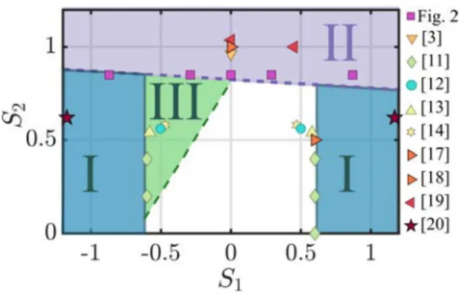
The mechanisms leading to the formation of the CRZ above a coaxial injector are now further scrutinized by reporting the results from Fig. 2 together with results frompast studies inadiagramshownin Fig. 3. Rise of the adverse pressure gradient ∂p/∂z on the centerline axis in a swirling flow originates from the decay of the azimuthal velocity given by [3, 11, 12]:
∂p ∂z r=0 ' −2 Z R 0 ρ|uθ| r ∂|uθ| ∂z dr (2)
where r= R is the radial position at the sidewalls. A first configuration leading to the formation of a CRZ in Fig. 2 is associated to a high value of the inner swirl number |S1|> 0.6.This region is noted I in Fig. 3.
Decay of uθin the central stream is sufficient to increase
the adverse pressure gradient in Eq. (2) leading to a CRZ located at the outlet of the central tube. This mechanism prevails in [20] or in Fig. 2 with S1 = ±0.87. Another
combination is when |S1| < 0.6. If S2 is high enough,
the tangential momentum remaining after mixing of the
Figure 3:Map of the different regimes with a CRZ above the coaxial
injector as a function of S1and S2. I) Region with |S1|> 0.6. II)
Re-gion with global swirl number S1+2> 0.7. III) Counter-swirl region
with S2< 0.6
central and the annular jets can generate a CRZ. This second mechanism takes over further downstream the injector outlet and is well predicted by the global swirl number S1+2defined byEq. (1).A rough limit is defined
byS1+2 & 0.7thatis added in Fig. 3and delineates re-gion II. This situation is observed when S1= 0 in [3, 5],
for S1 ≥ 0 in [17–19] or in Fig. 2 for S1 ≥ 0. The last
situation corresponds to coaxial jets with moderate swirl levels S1andS2 ∼ 0.5 that producea CRZ only when they are counter-rotating. In this configuration, noted III in Fig. 3, the decay of the azimuthal velocity ∂|uθ|/∂z is
faster for counter-swirling jets, leading to the formation ofaCRZ[11, 12].
The three regimes identified in Fig. 3 enable to re-port the results from many past studies in whichaCRZ has been obtained for differentswirl levelsin the inner or outer streams, and with different swirler geometries.
This diagram highlights that coaxial jets with moder-ate swirl levels feature an intense CRZ when counter-rotating [11–14] and a weak [12] or no CRZ [11, 14] when co-rotating. The experiments conducted in this study with a high swirl level in the annular jetindicate
that swirling the inner jet in counter- and co-rotating di-rection leads to the formation of a CRZ and that its po-sition directly depends on the values of |S1| and S1+2.
3. Impact on S1on the flame structure and flow field
The structure of the reacting flow is analyzed with the PIV/OH-PLIF setup for the same injection conditions as in Fig. 2 (datasetD2). Mean OH-PLIF images are
rep-resented in Fig. 4 superimposed to the velocity field in the axial plane of the burner. Instantaneous snapshots of the synchronized PIV and OH-PLIF diagnostics are provided in the supplemental material for the same op-erating conditions.
Figure 4: OH-PLIF/PIV measurements for flames at S2= 0.85, J = 0.75 and S1(D2dataset) varying from S1= −0.87 to 0.87. Mean OH-PLIF
signal is shown in color scale. The average velocity field is superimposed with white arrows. The recirculation zone is delineated by the thick white contours.
Figure 4 shows that combustion has disrupted the flow field. In the absence of inner swirl S1 = 0, the
CRZ is pushed downstream compared to non-reacting operation in Fig. 2. The flame lies in this case in the jet-like regime in agreement with results from Chen et al. [5]. When the inner swirl level slightly increases to |S1| = 0.29, the flame features a CRZ for both co- and
counter-rotating directions. In these cases, the width and length of the CRZ are drastically enhanced com-pared tonon-reacting conditions in Fig. 2. Enhance-ment of gas recirculation is also in agreeEnhance-ment with pre-vious studies reporting thattheheat release pushes the CRZ of swirl-stabilizedflamesmore upstream [3, 12]. The inner swirl level therefore has a considerable im-pact on the flame topology. A slight increase of |S1| in
Fig. 4 leads tothetransition of the flame from a jet-like regime for S1 = 0 to a CRZ regime when |S1| = 0.29
but the flame remains anchored on the central tube. It can be noticed that flame with S1 = −0.29 is not
per-fectly symmetric. This is attributed to asmall tilting of
the inner tubewith respect to the axis ofthe outer chan-nel. This asymmetry remains however small. Whenthe inner swirl is further increased to|S1|= 0.87, the CRZ
is pushed closer to the injector outlet, and the reaction layer becomes detached from the central injector rim.
The position of the CRZ in Fig. 4 is used to explain the flame liftoff transition as sketched in Fig. 5. When |S1| ≤ 0.29, the flame is anchoredon the central fuel
rim. A reaction layer starts in the wake of the injector rim at the interface between the central fuel stream and the annular oxidizer stream. When |S1|= 0.87, the CRZ
protrudes inside the central injector leading to apartial flowblockage of the inner fuel stream. The central jet is thusdivertedin the radial direction with high velocities. This drastically increases the shear stress in the wake of thefuelinjector rim. Enhancement of strain leads to
ex-|S
1|=0.87
Reaction layer:low velocity zone CH4/oxidizer CH4/burned gases oxidizer fuel
gases
Figure 5: Schematic representation of the two causes leading to flame liftoff when |S1|= 0.87.
tinction of the diffusion reaction layer in the wake of in-jector rim and the flames stabilizes further downstream close to the CRZ.
When the inner swirl number is high enough |S1| ≥
0.6 to sustain a CRZ by itself,partial flowblockage of the central fuel stream locally occurs for both co- and counter-rotating directions. The flame liftoff height is in this case the same for S1= ±0.87 as shown by Fig. 4.
When the inner swirl drops below |S1| < 0.6, the
pres-ence of the CRZ at the injector outlet also depends on the interaction between the two swirling jets. In that case, the CRZ in Fig. 4 is located more upstream for S1= 0.29 than for S1= −0.29.
Impact of the co- and counter-rotating direction of the inner swirlhas beeninvestigated for a broader range of operating conditions(D4dataset)by varying S1
be-tween −0.87 and 0.87, S2 from 0 to 1.1 and J from
0.75 to 3, leading to about 340 operating conditions.
This parametric analysis confirmsthat the rotation di-6
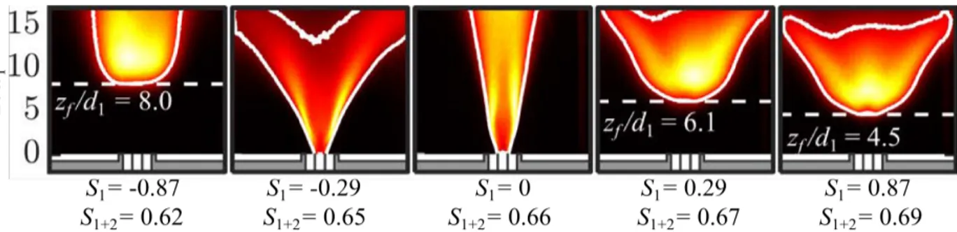
Figure 6: OH∗Chemiluminescence intensity signalforoxy-flames featuring different inner swirl numbers from S
1 = −0.87 to S1 = 0.87 (D3
dataset,S2 = 0.75 and J = 0.75). The Otsu contour [23]corresponds to the thickenedwhite contour. The global swirl numberS1+2definedby Eq. (1) is reported at the bottom of each flame.
Figure 7:Dimensionlessliftoff height zf/d1with respect to the global
swirl number S1+2as definedbyEq. (1). Only flames with a liftoff height higher than zf/d1 > 0.4 have been retained. Data points are
colored bythe value of theinner swirl number (D4dataset).
rection barely alters the flame liftoff transition when the inner swirl number is high enough |S1| > 0.6. For
low swirl numbers |S1| < 0.6, an example where the
rotation direction changes the liftoff transition is dis-played in Fig. 6 with OH∗chemiluminescence images
(D3 dataset). In this case, the flame is lifted above the injector for S1 = 0.29 and anchored to the nozzle rim
for S1= −0.29.
4. Impact of S1for lifted flames
Impact of inner swirl S1 in co- and counter-rotating
directions is now investigated only for the lifted flames stabilized downstream the coaxial injector. Three of them are represented in Fig. 6 showing that the flame leading edge position zf is very sensitive to the
rota-tion direcrota-tion, and therefore to the amount of swirl re-maining after the jets have mixed. The value of the global swirl number S1+2 indicated in Fig. 6 shows a
very good correlation with the evolution of the liftoff
height zf. When S1 is counter-rotating, S1+2decreases
and the flame is pushed downstream, whereas S1+2
in-creases and zf decreases when S1is co-rotating.
The analysis proceeds by plotting the flame liftoff height zf/d1 with respect to S1+2 in Fig. 7 for all the
lifted flames investigatedwhenzf/d1 > 0.4. This
cor-responds toa series of190 flames obtained for different
values ofS1, S2and J. The flames operated at S1 = 0
or -0.29could not belifted and are therefore discarded [10]. Data colored bythe value of theinner swirl num-ber S1collapse on a single curve in Fig. 7forboth
co-and counter-rotating configurations. The liftoff height zf/d1decreases when S1+2increases.
Analysis of Eq. (1) for S1+2is used to get further
in-sight on the structure of flow exhausting from a dual swirl coaxial injector.A first order perturbation analysis yields δS1+2= (d1/d2)αδS1+(1−α)δS2+βα2A2/A1δJ,
with β= (S2− d2/d1S1).The ratio A2/A1is often large
for coaxial injectors (9.3 in the present study) leading to small values for α when J is nottoosmall. In this case, changing the outer swirl number S2has a much bigger
impact on S1+2 than changing S1. This explains why
variations of the inner swirl number from S1 = −0.87
to 0.87 in Fig. 6 only reduce zf/d1 from 8.0 to 4.5. In
configurations withasmall annular velocity, α is equal to unity: the coaxial jet is governed by the inner swirl number S1, as in [8, 9].
For all the investigated lifted flames, the parame-ter β is positive β > 0. Increasing the momentum flux ratio J therefore reduces S1+2, leading to a
reduc-tion of the flame liftoff height zf/d1. By noticing that
S2− S1+2= αβ, the relationship between the inner and
the outer swirl numbers β > 0 also shows that the global swirl number is smaller than the one in the annular chan-nel S1+2 < S2. This number S1+2 must however not
be used to interpret detachment of the flame front from the central injector rim. In Fig. 6, the flame is lifted for S1+2= 0.62, 0.67 and 0.69 but anchored for S1+2= 0.65
and 0.66. Liftoff of O2-enriched flames is controlled by
the value of S1 leading to apartialblockage of the fuel
stream at the outlet of the central injector as described in the previous section.
The global swirl number S1+2therefore constitutes a
useful dimensionless number to determine the evolution of the flame liftoff height zf/d1 of oxy-flames
exhaust-ing from a dual swirl injector. It models the influence of S1, S2and J relying on the hypothesis that the inner
and outer jet momentums have mixed.
Conclusion
Impact of co- and counter-rotating directions of swirl in a coaxial injector has been investigated for O2
-enrichedair methane diffusionflames with a parametric approach and the help of optical diagnostics in reacting and non-reacting conditions. It has been found that the dynamics of a counter-rotating swirl injector with a high annular swirl number exhibits a different behavior than the flow obtained from injectors with a moderate annu-larswirl number. In this work, counter-swirlin the inner fuel streamweakens the central recirculation zone while co-swirl enhances it. One major outcome of this study regarding co- and counter-swirls is to separate near-field effects occurring at the outlet of the injector from swirl dissipation happening further downstream after the jets have mixed.
At the outlet of the injector, transition to liftoff for O2-enriched flames is caused by thepartialblockage of
the inner fuel stream when the central recirculation zone stabilizes at the outlet of the fuel injector. This flow blockage leads to high transverse velocities and high strain rates in the wake of the injector rim and is more influenced by the magnitude of the inner swirl number |S1| than its rotation direction.
Further downstream, after the inner and outer jets have mixed, the liftoff height zf/d1of the non-premixed
oxy-flames exhausting from a dual swirl injector has been shown to scale with a global swirl number S1+2
defined by Eq. (1)for a large range of operating condi-tions −0.87 ≤ S1≤ 0.87, 0.6 ≤ S2≤ 1.1, 0.75 ≤ J ≤ 3,
for both co- and counter-swirl configurations.
References
[1] N. Syred, N. Chigier, J. Beer, Flame stabilization in recirculation zones of jets with swirl, Proc. Comb. Inst. 13 (1) (1971) 617– 624.
[2] N. A. Chigier, J. M. Be´er, Velocity and static-pressure distri-butions in swirling air jets issuing from annular and divergent nozzles, J. Basic Eng. 86 (4) (1964) 788–796.
[3] V. Tangirala, R. Chen, J. F. Driscoll, Effect of heat release and swirl on the recirculation within swirl-stabilized flames, Com-bust. Sci. Technol 51 (1-3) (1987) 75–95.
[4] R.-H. Chen, J. F. Driscoll, The role of the recirculation vortex in improving fuel-air mixing within swirling flames, Proc. Comb. Inst. 22 (1) (1989) 531–540.
[5] R.-H. Chen, J. F. Driscoll, J. Kelly, M. Namazian, R. Schefer, A comparison of bluff-body and swirl-stabilized flames, Combust. Sci. Technol. 71 (4-6) (1990) 197–217.
[6] D. Feikema, R.-H. Chen, J. F. Driscoll, Enhancement of flame blowout limits by the use of swirl, Combust. Flame 80 (2) (1990) 183–195.
[7] A. Degen`eve, R. Vicquelin, C. Mirat, B. Labegorre, P. Jour-daine, J. Caudal, T. Schuller, Scaling relations for the length of coaxial oxy-flames with and without swirl, Proc. Comb. Inst. 37 (4) (2019) 4563–4570.
[8] S. Yuasa, Effects of swirl on the stability of jet diffusion flames, Combust. Flame 66 (2) (1986) 181–192.
[9] M. Cha, D. Lee, S. Chung, Effect of swirl on lifted flame char-acteristics in nonpremixed jets, Combust. Flame 117 (3) (1999) 636–645.
[10] A. Degeneve, C. Mirat, J. Caudal, R. Vicquelin, T. Schuller, Ef-fects of swirl on the stabilization of non-premixed oxygen en-riched flames above coaxial injectors, J. Eng. Gas Turb. Power, accepted.
[11] B. T. Vu, F. Gouldin, Flow measurements in a model swirl com-bustor, AIAA Journal 20 (5) (1982) 642–651.
[12] F. Gouldin, J. Depsky, S.-L. Lee, Velocity field characteristics of a swirling flow combustor, AIAA journal 23 (1) (1985) 95–102. [13] J. Ramos, H. Somer, Swirling flow in a research combustor,
AIAA journal 23 (2) (1985) 241–248.
[14] J. Mehta, H.-W. Shin, D. Wisler, Mean velocity and turbulent flow-field characteristics inside an advanced combustor swirl cup, in: 27th Aerospace Sciences Meeting, 1989, p. 215. [15] Y. Hardalupas, J. Whitelaw, Characteristics of sprays produced
by coaxial airblast atomizers, J. Propul. Power 10 (4) (1994) 453–460.
[16] M. Soltani, K. Ghorbanian, M. Ashjaee, M. Morad, Spray char-acteristics of a liquid–liquid coaxial swirl atomizer at different mass flow rates, Aerosp. Sci. Technol. 9 (7) (2005) 592–604. [17] J. Truelove, T. Wall, T. Dixon, I. M. Stewart, Flow, mixing and
combustion within the quarl of a swirled, pulverised-coal burner, Proc. Comb. Inst. 19 (1) (1982) 1181–1187.
[18] T. Dixon, J. Truelove, T. Wall, Aerodynamic studies on swirled coaxial jets from nozzles with divergent quarls, J. Fluids Eng. 105 (2) (1983) 197–203.
[19] T. Mahmud, J. Truelove, T. Wall, Flow characteristics of swirling coaxial jets from divergent nozzles, Journal of fluids engineering 109 (3) (1987) 275–282.
[20] Y. Sung, G. Choi, Non-intrusive optical diagnostics of co-and counter-swirling flames in a dual swirl pulverized coal combus-tion burner, Fuel 174 (2016) 76–88.
[21] H. K. Kim, Y. Kim, S. M. Lee, K. Y. Ahn, Emission character-istics of the 0.03 mw oxy- fuel combustor, Energy Fuels 20 (5) (2006) 2125–2130.
[22] A. Degen`eve, P. Jourdaine, C. Mirat, J. Caudal, R. Vicquelin, T. Schuller, Effects of a diverging cup on swirl number, flow pat-tern and topology of premixed flames, J. Eng. Gas Turb. Power 141 (3) (2019) 031022.
[23] N. Otsu, A threshold selection method from gray-level his-tograms, IEEE Trans. Syst. Man Cybern 9 (1) (1979) 62–66. [24] Q. Wang, L. Hu, X. Zhang, X. Zhang, S. Lu, H. Ding, Turbulent
jet diffusion flame length evolution with cross flows in a sub-pressure atmosphere, Energy Convers. Manag. 106 (2015) 703– 708.