HAL Id: in2p3-00176117
http://hal.in2p3.fr/in2p3-00176117
Submitted on 2 Oct 2007HAL is a multi-disciplinary open access archive for the deposit and dissemination of sci-entific research documents, whether they are pub-lished or not. The documents may come from teaching and research institutions in France or abroad, or from public or private research centers.
L’archive ouverte pluridisciplinaire HAL, est destinée au dépôt et à la diffusion de documents scientifiques de niveau recherche, publiés ou non, émanant des établissements d’enseignement et de recherche français ou étrangers, des laboratoires publics ou privés.
MAYA: An active-target detector for binary reactions
with exotic beams
C.E. Demonchy, M. Caamaño, H. Wang, W. Mittig, P. Roussel-Chomaz, H.
Savajols, M. Chartier, D. Cortina-Gil, A. Fomichev, G. Frémont, et al.
To cite this version:
C.E. Demonchy, M. Caamaño, H. Wang, W. Mittig, P. Roussel-Chomaz, et al.. MAYA: An active-target detector for binary reactions with exotic beams. Nuclear Instruments and Methods in Physics Research Section A: Accelerators, Spectrometers, Detectors and Associated Equipment, Elsevier, 2007, 583, pp.341-349. �10.1016/j.nima.2007.09.022�. �in2p3-00176117�
MAYA: an Active-Target Detector for Binary
Reactions with Exotic Beams
C.E. Demonchy
1, a, M. Caama˜
no
b,a, H. Wang
2, a, W. Mittig
a,
P. Roussel-Chomaz
a, H. Savajols
a, M. Chartier
c,
D. Cortina-Gil
b, A. Fomichev
d, G. Fr´emont
aP. Gangnant
aA. Gillibert
e, L. Giot
3, a, M.S. Golovkov
d, B. Jurado
1, a,
J.F. Libin
aA. Obertelli
e, E. Pollaco
e, A. Rodin
d,
Ch. Spitaels
aS. Stepantsov
d, G. Ter-Akopian
d. R. Wolski
d,f.
a
GANIL, B. P. 55027, F-14076 Caen Cedex 5, France
bUniv. de Santiago de Compostela, E-15706 Santiago de Compostela, Spain cOliver Lodge Laboratory, University of Liverpool, Liverpool L69 7ZE, U.K.
dFLNR/JINR, Dubna, P.O. Box 79 10100 Moscow, Russia
eCEA/DSM/DAPNIA/S Ph N, Saclay, 91191, Gif-sur-Yvette cedex, France fThe Henryk Niewodniczanski Institute of Nuclear Physics, Krakow, Poland
Abstract
With the recent improvements on production of radioactive beams in facilities such as SPIRAL at GANIL, a larger area of the nuclear chart is now accessible for experimentation. For these usually low-intensity and low-energy secondary beams, we have developed the new MAYA detector based on the active-target concept. This device allows to use a relatively thick target without loss of resolution by using the detection gas as target material. Dedicated 3-D tracking, particle identification, energy loss and range measurements allow complete kinematic reconstruction of reactions taking place inside MAYA.
Key words: radioactive beam, active target, direct reactions, exotic nuclei.
1
present address: Centre d′Etudes Nuclaires de Bordeaux Gradignan - CENBG
UMR 5797 CNRS/IN2P3 Universit´e Bordeaux 1, Chemin du Solarium BP 120 33175 GRADIGNAN Cedex, FRANCE
2 present address: IMP, Lanzhou, China
3 present address: Subatech, Ecole des mines, La chantrerie, 4 rue Alfred Kastler,
BP 20722 44307 Nantes-cedex 3, FRANCE Manuscript
1 Introduction
Among the experimental methods employed to study the structure of nuclei far away from the valley of stability, direct reactions, such as elastic and inelastic scattering or transfer reactions, are important because of their selective nature and their relative simplicity in understanding the experimental observables, giving one of the most powerful and incisive methods to elucidate spectro-scopic and structural characteristics of the particles involved. Such informa-tion is most readily extracted using reacinforma-tions in which one of the participants has a relatively simple structure, e.g. 1H or 4He. For this reason, the
reac-tions induced by radioactive beams usually correspond to inverse kinematics (see e.g. ref. [10]), and therefore detection systems are optimized for these experimental conditions. The information of interest is then extracted from kinematical characteristics of the reaction products such as their scattering angles or energies.
The use of direct reactions with exotic nuclei imply several difficulties that should have to be taken into account. The most exotic nuclei are usually the most interesting nuclei but their production rate decreases exponentially with the increase of the proton-neutron imbalance and they are often available with a few thousand or hundred counts per second. In general this is many orders of magnitude lower than the production rates for primary beams used to study stable nuclei. In order to counterbalance this effect, high-efficiency setups and thick reaction targets are required, leading to large uncertainties in the kinematic reconstruction and energy resolution when low energy particles are involved. Another problem is related to the fact that the detection of a low energy recoil product is often rather difficult. Moreover, the detection in coincidence of the reaction products is desirable in order to enhance the selection of reaction channels and reduce background contamination.
The idea of an active target, in which the target and detection setup are part of the same device, overcomes many of these difficulties. Low rates associated with the production of exotic nuclei are counterbalanced by detection effi-ciencies which can approach 100 % . An event-by-event 3-D tracking allows to eliminate the influence of the energy loss associated with thick targets. In some cases, target thickness can even be increased until the incident beam particles are completely stopped in the target-detector, optimizing in this way the reaction rates. Finally, low recoil energies may be detected with an ex-tremely low energy threshold. In addition, in the case of unbound reaction products, their decay products can also be detected in the production target itself. Another feature consists in the possibility to obtain excitation func-tions for specific reacfunc-tions with a single tuning of the accelerator, and thus optimizing the available beam time.
The active-target concept was rarely applied in nuclear physics research, where only few active-target were developed. Previous devices were planned to be used with specific configurations, resulting in a reduced experimental flexibil-ity. The IKAR detector [1] was developed for beam energy around 1 GeV. It was used with H2 gas at 10 atm. Another detector, MSTPC
(Multiple-sampling and Tracking Proportional Chamber) [2], was developed to be used at atmospheric pressure.
The requirements for the proposed active target detector are reviewed in sec-tion 2, followed by the detector design in secsec-tion 3. The associated electronics and general data analysis are described in section 4. Section 5 presents some experimental results obtained. Further detailed descriptions of the detector results can be also found in [8, 9].
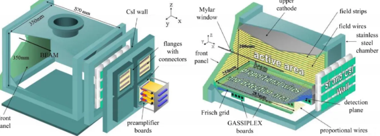
Figure 1. Schematic view of the external design (left) and the internal structure (right) of the MAYA detector.
2 Detector Requirements
The present version of the active-target detector, called MAYA, is built on the basis of a gaseous room-temperature drift chamber, with the filling gas playing the role of reaction target. A wide selection on target species is achieved via the different options for filling gases. Light targets such as H2, D2 or Helium
are mainly available in gaseous form, allowing their use as inverse kinematic reaction targets. At the same time the use of heavier targets, such as carbon or argon, are also possible through mixed compounds.
Target thickness is controlled by the pressure of the filling gas. However, the cost and security requirements are limiting factors for size and operational pressures of gaseous detectors. In the present case the pressure was limited to a maximum of 3 atm.
Concerning the dimensions of the detector, a reasonable drift time of the ionized electron cloud may be obtained applying a relatively high voltage within 20 cm of maximum drift distance. The width of the detector is set to 25 cm with 28 cm of thickness. These dimensions allow to stop and detect most of the SPIRAL [11,12] beams and their reaction products. A 25×20 cm2
wall of Cesium-Iodide, ocassionally preceded with Silicon ancillary detectors, is placed at the back side of the detector in order to get information from those reaction products with enough energy to leave the gas volume.
The information extracted from the reaction products stopped inside the gas volume includes tracking reconstruction and range measurement through the charge collected in a cathode segmented in 5 mm side hexagonal pads. The resolution of position and range measurements with this geometry achieves 1 mm for particle ranges around 10 cm. As a reference, the TRIM code [14] cal-culates a range straggling around 1% at atmospheric pressure for light charge particles with 10 cm ranges. A hexagonal geometry of the cathode pads is adopted in order to reduce the influence of preferential directions in the tra-jectory reconstruction. Finally, the detection of low energy loss particles is assured with a plane of amplification proportional wires placed above the seg-mented cathode. The result is an extremely low detection threshold, suitable for reaching kinematic areas not accessible with standard solid targets.
3 Detector design
3.1 Detector Chamber
The detector chamber is a nearly cubic stainless-steel container, about 40 cm wide, with three large openings at the front, rear and bottom, and flanges on the left, right and top panels used for signal output, gas flow and high voltage input. A frame is inserted between the container and the rear panel for holding 5×5 cm2
ancillary detectors set in four rows of five detectors. The rear panel has also four openings for square flanges, used for signal output. The proportional wires preamplifier cards are directly plugged on one of these flanges on airtight connectors.
The front panel is a machined piece of epoxy with a 1.3 cm diameter Mylar entrance window. The thickness of the entrance window is chosen acording to the gas pressure, which can be safety set up to 3 atm, including for explo-sive gases. As an example a 6 µm thick window was used for a gas pressure of 2 atm. In addition, the vessel construction and materials used have been chosen to minimize out-gassing, since the pollution by even small amounts of impurities can drastically alter the amplitude of the signals, due to
electron-ion recombinatelectron-ion [15]. As an example, during a recent experiment where the detector was filled with D2 at 1 atm and sealed, a change in signal amplitude
less than 20 % was observed after five days of running.
Figure 1 shows a schematic view of the external design of MAYA.
3.2 Internal design
The internal design of MAYA can be divided into three main parts: an active volume containing the filling gas where the reactions and ionization paths oc-cur; a detection area where the ionization patterns are amplified and recorded; and the ancillary detectors wall placed at the back side for detecting escaping particles. The internal structure is fixed to the removable front panel by four machined bars, providing an easy access. A schematic view of the internal design of MAYA is shown in Figure 1.
The active volume defined by the filling gas is a 283 mm long, 258 mm wide and 200 mm high volume. On the top side there is a stainless steel cathode, and on the lower side a Frisch grid separates the active volume from the detection area. The active volume is surrounded by printed circuit boards, mounted on the front and side panels, with copper field strips for assuring the homogeneity of the electric field applied between the upper cathode and the Frisch grid. The strips are 3 mm wide and 1 mm spaced. The forward board of field strips is replaced by a frame holding 50 µm Cu-Be field wires, spaced in 2 mm, to allow escaping particles to reach the wall of ancillary detectors.
The detection area is separated from the active volume with a Frisch grid. This is a plane of 50 µm Cu-Be field wires, 2 mm spaced, perpendicular to the beam direction. Below the Frisch grid the plane of proportional wires is placed at 15 mm. The proportional wires width and their distribution can be chosen depending on the experimental conditions. Gold-plated Tungsten wires of 5, 10 and 20 µm, with 2 or 2.3 mm spacing were already used. The proportional wires are meant to induce signal in the cathode plane 10 mm below. The cathode is segmented in 37×35 5 mm side hexagonal pads, from which 32×32 pads are used for charge collection. The signals induced on the cathode pads are collected and delivered to the acquisition system by GASSIPLEX chips connected underneath the cathode board. This is an eight layers board which includes connections, grounding, and power management.
Finally, the ancillary detector wall used to stop and detect particles escaping from the gas volume may be occupied with different detectors. In experiments performed, 700 µm thick, 5x5 cm2
silicon detectors, and 1 cm thick, 5×5 cm2
CsI crystals, were already used. Further modifications already included beam shielding to avoid collection of charge induced by the beam particles, providing
a better separation for reaction products with lower energy loss.
Figure 2. Upper view of hexagonal cathode pads. The arrow shows the direction of incoming beam particles.
3.3 Detection principle
The charged particles inside the detector ionize the filling gas along their tra-jectories releasing electrons that drift toward the amplification area by means of a high electric field, typically 10 kV to 15 kV, applied between the up-per cathode and the Frisch grid. The electrons traverse the Frisch grid, which shields the wires and the anode from the charge induction by electrons and ions above the grid [16], and they are accelerated around the proportional wires where a high voltage, between -1 kV and -4 kV, is applied. The ac-celerated electrons ionize the surrounding gas releasing positive ions which induce a mirror charge in the pads below. The amplified signal collected on the pads depends on the electric field applied on the wires, reaching factors of 103
up to 104
. The pattern of charges collected in the individual pads result in a projection of the trajectories of the charge particles that loss enough en-ergy to induce a measurable signal. See Figure 3 for a schematic review of the ionization process.
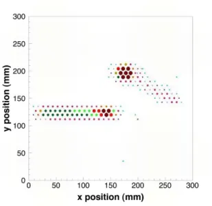
Figure 4 shows experimental and simulated patterns for an elastic p(8
He,8
He)p reaction at 3.9AMeV, with an angle of 60 deg for the proton recoil. The wires corresponding to the beam region in the experimental plot are a factor of two thicker thicker in order to balance the difference in energy lose between the proton and the 8He, making possible the detection of both reaction products
with the same configuration. The amplification of the beam region in the simulated patter is reduced by a factor 10 for reproducing the experimental conditions. We can observe a good agreement between the experimental and simulated events.
Figure 3. Schematic diagram of the ionization process and the MAYA detection principle.
Figure 4. Charge collected in the segmented path corresponding to a simulated (upper panel) and experimental (lower panel) p(8He,8He)p reaction at 3.9 AMeV, within
1060 mbar of C4H10. The reaction takes place at 100 mm from the entrance window,
with a recoil angle for the proton of 60o. The area of each dot is proportional to the
charge collected in the corresponding pad. 4 Electronics and data analysis
4.1 Electronics
The signals released from the proportional wires are used to perform energy and time measurements. Usually, an external beam detector consisting by a small drift chamber [17] located upstream of MAYA provides the start sig-nal for the time measurement. The electronics for the 32 groups of wires are
mounted on three boards, plugged on the rear-panel flange. They consist of a set of preamplifiers for 39 channels, resistors for the high voltage input and the capacitors for decoupling the preamplifiers and the high voltage. These boards are placed outside the vessel for easy maintenance. It is also possible to extract a signal output from groups of wires of the Frisch grid. This output can be used in the acquisition logic or as an auxiliary energy loss measurement. The collected charges on the cathode pads are read out by GASSIPLEX chips followed by a sequencer [18] and a flash-ADC [19]. Each GASSIPLEX chip performs amplification, shaping, and multiplexing for 16 channels. In total, MAYA uses seventeen boards of four chips giving 1088 channels for treating the 1024 (32×32 pads) needed. The gain of the GASSIPLEX is set at 3.6 mV/fC, equivalent to 160 mV/MeV for Si or 16 mV/MeV for a gas detector without amplification. The GASSIPLEX chips memorize the maximum of the amplitudes at the output of the the amplifiers 1.2 µs after the signal is induced in each pad. An external signal from the wires above starts the recording of the amplitudes from the pads, which are kept in memory until another signal provided by a sequencer starts the delivering of the recorded amplitudes to the acquisition system. The reading is controlled by a clock signal provided by the sequencer. For each rising front of the clock the memorized amplitude from each input channel is connected to the output of the GASSIPLEX. The same front is delayed and sent to an Analog to Digital Converter module for synchronizing reading and coding. After a proper calibration of the pads for gain matching it is possible to apply a general threshold for reading only those pads with non-zero induction, reducing the acquisition dead time.
4.2 Data analysis
The data analysis is mainly focused on the reconstruction of the reaction through the tracking of the particles trajectories with the induced pattern on the segmented cathode and the time and energy measurements on the proportional wires. The detector was designed for the study of binary reactions in inverse kinematics, which reduces the complexity of the ionization trace pattern. A single reaction plane exists, and a left scattered particle is always associated with a right scattered particle with respect to the incident beam particle, due to momentum conservation.
The charges induced in the segmented pads are used to reconstruct the origi-nal ionizing path of the particle. The angles projected on the cathode plane of the detected particles are extracted fitting to straight lines the charge pattern. The positions of the charges to be fit are corrected to avoid digitalization due to the finite size of the pads. The correcting methods are usually based on center of gravity calculations around the maxima of charges, performed with the Secant Hyperbolic Squared method (SECHS) [20, 21], which takes into
account the punctual charge induction behaviour. The ranges of the particles are obtained as the distance between the end of the trajectory and the reac-tion vertex, which is usually calculated as the intersecreac-tion of the trajectories of the particles involved. The methods used for estimating the stopping point of each trajectory depend strongly on the experimental conditions. For rela-tively medium energy particles, a well defined Bragg peak can be treated for determining the stopping point with precissions around 1 mm [8]. However, it is possible to treat situations where the ionization path starts after the Bragg peak, typically with particles at energies well below than 1 MeV/u. In this latter case a dedicated treatment of the ionization profile along the trajec-tory can be used for extracting the stopping point with uncertainties around 2 mm [7].
The projected angles and ranges are then corrected with the reaction plane angle. This is calculated with the drift times measured from the ionizing parti-cle tracks up to each anode wire. The drift times are translated into distances via the drift velocity, measured with the well-defined trajectories of the beam particles. A simple fit extracts the reaction plane angle respect to the plane of anode wires and the segmented cathode.
Measurements of the total energy loss in the filling gas are performed either with the sum of the charges induced on the cathode pads along the particle trajectory, either with the sum of the signal collected in the proportional wires. From those particles that do not stop inside the filling gas but they are stopped and detected in the ancillary detector wall measurements of total energy, en-ergy loss and E-∆E identification are available depending on the type of de-tector used. In recent experiments [7], Cesium-Iodide crystals allowed particle identification treating the corresponding slow and fast signals from the CsI light output. Silicon detectors were also used for providing ∆E measurements before stoping the particle in a following CsI detector in other experiments.
5 Experimental results
5.1 Particle and reaction identification and separation.
For those particles stopping inside the filling gas of MAYA, the identification is obtained from the unique relation existing between the energy of the particle and its range in a given material. In general, for a particle of mass M and charge Z, with an energy E:
Range ∝ E
2
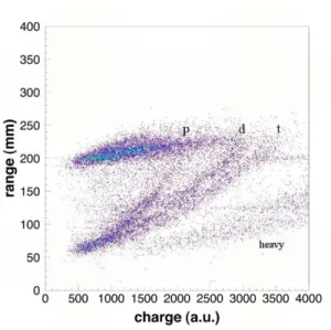
Figure 5. Identification plot for products of a 3.5 AMeV8He beam impinging on 525
mbar of C4H10, with an interaction point corresponding to a reaction energy around
2.6 AMeV.
The measurement of the charge induced on the segmented cathode is assumed to be directly related with the energy loss, that is, the total energy when the particle stops in the gas. Figure 5 shows a typical range-charge identification plot, with products from different reactions occurring for a 8
He beam at 3.5 AMeV in 525 mbar of C4H10, with a reaction energy around 2.6 AMeV.
Lines corresponding to protons, deuterons and tritons are clearly identified for ranges above 100 mm. The upper horizontal line, placed around 200 mm, corresponds to the geometric limits of the detector, populated with particles leaving the active volume. For those particles a E-∆E identification is possible with the help of the ancillary detectors wall placed at the back side, using the charge collected in the gas ionization as ∆E measurement, and added to the energy collected in the ancillary detector where the particle is stopped for a total energy measurement.
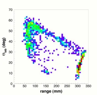
The identification of the different reactions produced in the active volume is performed by the reconstruction of the reaction kinematics along with the selection of the particles involved. Figure 7 shows the correlation between the measured recoil angle and range for protons selected on an identification plot similar to Figure 5 for a 8He+p at 3.5 AMeV. The elastic scattering appears
clearly for ranges above 100 mm, when compared to calculated kinematics showed in Figure 6. The line at 300 mm is due again to the geometry of the detector.
Fig-Figure 6. Calculated kinematic lines for some expected reaction channels in 8He+p
at 2.0 AMeV.
Figure 7. Scattering angle vs. range of protons from elastic scattering of8He at 3.41
AMeV in 1 atm. of C4H10.
ures 8 and 9 show kinematic lines reconstructed with the energy of the recoil partner and the range of the scattered for 8
He(p,p)8
He at 3.5 AMeV after identification of the recoil protons in the ancillary detectors. A resolution in excitation energy of 160 keV (FWHM) is obtained from the elastic correla-tion line. Figure 9 shows the same plot for 8He(p,d)7He after identification of
deuterons. The corresponding kinematic line is in this case broader due to the width of the states in the unbound 7He system and the subsequent neutron
A possible application to the observation of radioactive decay is illustrated by Fig. 10. A 8Li nucleus decays in a β and two α particles and it is observed
after the production of the 8
Li nucleus, the decay is observed in coincidence detection with an uncorrelated event triggered by a beam projectile.
Figure 8. Proton energy vs. helium range from a 3.5 AMeV 8He beam. The lines
represent the kinematics for (p,p) elastic scattering at ground state and at an energy of 1 MeV.
Figure 9. Deuteron energy vs. helium range from a 3.5 AMeV 8He beam. The
lines represent the kinematics for the (p,d) transfer reaction leading to the unbound ground state of 7He, and to excited states at 0.5 and 1 MeV above the ground state
shown for reference. As can be seen by comparison with fig. 8, the width of the distribution is essentially due to the finite width of the states in7He.
Figure 10. Decay event uncorrelated with the beam: the trace in the center is the beam and the one in the upper right corner is the8Li decay in two alpha (the main
spot) and one β (the tail). 5.2 Resolution
A close value to the intrinsic resolution of the trajectory reconstruction was obtained by applying and comparing different reconstruction methods to ex-perimental events, resulting in 0.84 mm (FWHM) of deviation from the fitted trajectory. Estimations on the nominal angular resolution can also be obtained from the position resolution. For a typical range of 100 mm an upper value of the angular resolution is set at 0.7 deg for a trajectory angle of 45 deg. Reaction vertex position resolution can be deduced from trajectory and an-gular resolutions when it is determined as the crossing point of different tra-jectories. In these cases the resolution is mainly dominated by the width of the charge distributions in the cathode plane of the involved trajectories, with typical values around 3 mm. The resolution of the stopping point can be esti-mated comparing measured ranges with predictions from codes such as SRIM. Figure 11 shows the measured range for a collection of events of8He beam
pro-jectiles at 3.9 AMeV stopped in 1 atm of C4H10. The resulting range is 162.4
mm within a 1.2 mm FWHM distribution, where the SRIM code calculates 162.7 mm with a straggling of 3.25 mm. For particles produced in reactions in the filling gas the range is obtained as the distance between the reaction vertex and the stopping point, then the range resolution folds both position resolutions.
dependent on the experimental conditions of particle energy and gas pressure.
Figure 11. Range measurement for a 8He beam at 3.9 MeV/n in isobutane at a
pressure of 1atm. The insert shows a zoom of the peak region with the results for the range and its dispersion.
5.3 Experiments performed with MAYA
The detector was used in several experiments, under very different conditions. Table 1 summarizes the main characteristics of experiments performed up to now with MAYA at GANIL with exotic beams produced either in-flight with SISSI [13] or by the ISOL method with SPIRAL [12]. It shows the versatility and the uniqueness of the active target concept for the detection of slow re-coil particles. As an example, in the case of the 12C(8He,7H)13N reaction, the
properties of the unbound7
H system was deduced from the kinematic charac-teristics of 13
N, for which the range of energies to be considered was between 2 and 15 MeV. Such an experiment would have been impossible by standard methods using a solid target and a charge particle array, since the range of such a low energy ion hardly allows to get out of the target of reasonable thickness.
6 Conclusion
MAYA, an active-target detector to study binary reactions at low energy with radioactive beam was designed and built at GANIL. Electronics based on ASIC
Table 1
Different experiments performed with MAYA.
Beam Reaction Particle(s) detected in the gas Gas HV Cathode
8He at 3.9 AMeV p(8He,8He)p 1+nH,8−nHe C4H10 at 1 bar -16000 8He at 15.4 AMeV 12C(8He,7H)13N Nitrogen C
4H10 at 30 mbar -1600 25,26F at 50 AMeV 2H(25,26F,X)3He 3He D
2 at 2.2 bar -20000 56Ni at 30 AMeV 2H(56Ni,56Ni)2H∗ 2H D
2 at 1 bar -16000
technology, cost effective and already used in other detectors, was used. The experience and skills in building gaseous detectors at GANIL were extended in order to build the detector. The first experiments done with this new de-tector are producing very encouraging results, with resolutions on position reconstruction and angle measurement in good agreement with expectations. In addition, the first experiments with8
He beams have shown the ability of the detector to identify particles down to an energy threshold below 1 AMeV. The capabilities of MAYA for detecting and measuring experimental observables in extreme conditions allow direct measurements of the observables of low energy particles within a target thickness large enough to overcome the low cross sections. In addition, the 3-d tracking avoids common problems of strag-gling with a total reconstruction of the particle trajectory. These features have proved to be extremely useful in future experimental studies with secondary exotic beams near and beyond the drip lines, where large kinematic ranges are needed, including regions not accessible with the standard techniques.
References
[1] A. V. Dobrovolsky et al. Nucl. Phys B214 (1983) 1 [2] Y. Mizoi et al. Nucl. Instrum. Methods A431 (1999) 112 [3] W. Mittig et al. Nucl. Phys A722 (2003) 10c
[4] W. Mittig et al. NENS 2003 Conference Proceedings World Scientific, Singapure (2003) 133
[5] W. Mittig et al. Eur. Phys. J. A25 supplement 1 (2005) 263 [6] C.E. Demonchy et al. J. Phys. G31 (2005) S1831
[7] C.E. Demonchy et al. Nucl. Instr. and Meth. A573 (2007) 145
[8] C.E. Demonchy, ´Etude de R´eactions et d’ ´Etats Isobariques Analogues dans le Syst´eme 8He+p a Basse ´Energie a l’Aide de la Cible Active Maya thesis,
[9] M. Caama˜no, Production and Characterization of the7H Nuclear System thesis,
University of Santiago de Compostela, Spain (2006)
[10] W. Mittig, P. Roussel-Chomaz, Nucl. Phys A693 (2001) 495 [11] www.ganil.fr/spiral/index.html
[12] A.C.C. Villari and the SPIRAL group Nucl. Instrum. Methods B204 (2003) 31
[13] www.ganil.fr/operation/sissi/sissi.html [14] www.srim.org
[15] F.A. Maxfield and R.R. Benedict Theory of gaseous conduction and electronics Mc Craw-Hill Book Company Inc. New-York - London. (1941)
[16] F. Knoll Radiation detection and measurement 3rd edition, J. Winley & sons,
New York. (2000)
[17] M. MacCormick et al. Rapport GANIL R9802 (1998) [18] www.caen.it/nuclear/product.php?mod=V551, Sequencer [19] www.caen.it/nuclear/product.php?mod=V550, ADC [20] I. Endo et al. Nucl. Instrum. Methods A188 (1981) 51-58 [21] K. Lau and J. Pyrlik Nucl. Instrum. Methods A366 (1995) 298