Comparative study of PI and FUZZY DC-voltage control for Voltage
Oriented Control-PWM rectifier
A.FEKIK, H. DENOUN, N.BENAMROUCHE,N. BEYAHIA, M.ZAOUIA,S.HADDAD.
Laboratoire des Technologies Avancées de Génie Electrique
Faculté de Génie Electrique et Informatique
Université Mouloud Mammmeri de Tizi Ouzou, Algeria
arezkitdk@yahoo.fr
Abstract:-This paper deals with control strategies for a pulse width modulation (PWM) rectifier in order to
reduce the harmonics and consequently decrease the total harmonic distortion (THD) ratio of the line current and improve the power factor using voltage oriented control (VOC) based on the usual transformation between stationary coordinates α β and synchronous rotating coordinates d q. Furthermore, a comparative study of the DC voltage control will be undertake between a PI controller and Fuzzy logic controller to ensure a stable active power exchange. The modeling and then the simulation of this system under Matlab/Simulink/SimPowerSystem and Fuzzy logic toolbox showed clearly the supremacy of the second method while comparing the DC voltage responses.
Key-Words:PWM rectifier, VOC, Fuzzy Logic Controller, PI controller, THD, Decoupled controller.
NOMENCLATURE ea, eb, ec :power source voltages. uea, ueb, uec :rectifier voltages ia, ib, ic :power source currents.
R,L, C :line resistance, line inductance, capacitor.
S: Laplace operator.
f :frequency.
ω: supply frequency.
Sa, Sb, Sc: Switching state of the converter.
φ : phase voltage. is: output current. Vdc : direct voltage. id: load current. Rd: load resistance
.
1 Introduction:
With the development of power electronic converter technology, all kinds of inverters based on Pulse Width Modulation (PWM) have been widely used. At present, most of rectifier devices usually adopt non-controlled or semi-controlled rectification technology
[1][2][3]. Among the technical control of three-phase PWM rectifiers to reduce current harmonics and improve the power factor in the power grid, there is the Voltage Orientation Control (VOC) based the voltage estimate [4].
The active power exchange must be stable by insuring a DC voltage equal to its reference so that the PWM rectifier operates with a good efficiency. This can be carried out by using a control system able to regulate the DC voltage [5].
In this paper, two techniques to control the DC-voltage are considered, the first using a PI controller and the second using a fuzzy logic controller. First, the whole system is modeled and then a simulation is undertaken under Matlab environment. The comparative study shows that the performances using the fuzzy logic controller are slightly better that those obtained using a simple PI controller. In fact, the DC voltage response shows good rejections to disturbance of load with good dynamics. Moreover, the output voltage contains less harmonics reducing the THD ratio.
2 Modeling of a PWM rectifier:
The power circuit of the PWM rectifier
contains a bridge of six power transistors with anti-parallel diodes, which is used to carry out the PWM generation as well as the power bidirectional conversion, the general diagram of the PWM rectifier is shown in Fig. 1. The converter is supplied by a voltage source in series with an inductance and a resistance, which model the network. Generally, the network inductance is insufficient [6][10] to eliminate all the harmonics present in the current and voltage waveforms.
To attenuate the ripples due to the switching operation of the PWM rectifier, a series filter having a more significant inductance is needed. A load and a capacitor are connected simultaneously at the output of the converter. The capacitor is used as a voltage source and allows the rectifier to also operate as an inverter [9][10]:
Fig.1. General Diagram of the PWM rectifier The logical states impose the rectifier input voltages and are given as
�uuebea = S= Sab. V. Vdcdc
uec = Sc. Vdc
Thus the operation principle of the rectifier is illustrated by the following matrix system:
�uueaeb uec �=Vdc ⎝ ⎜ ⎛ 2 3 −1 3 −1 3 −1 3 2 3 −1 3 −1 3 −1 3 2 3⎠ ⎟ ⎞ �Sa Sb Sc �
The AC side can be modeled by the following equations: ⎩ ⎪ ⎨ ⎪ ⎧uea = ea− Ria− ldidta ueb = ea− Ria− ldidta uec = ea− Ria− ldidta (3)
AC currents ia, ib and ic are generated by voltage drops at impedances network boundaries (ea-uea), (eb-ueb) and (ec-uec),and then these currents will be modulated through the switches to provide the D.C.current idc such as [5]:
is = Saia+ Sbib+ Scic
The voltages vectors generated by the rectifier can be given by Table 1:
Table.1 Different switches configurations and the corresponding voltage vectors
(4) (2)
(1)
The vector representation of voltages generated by the rectifier is illustrated by Fig.2:
Fig.2. Voltage vectors generated by the rectifier
3
VOC strategy:
As in the Flow Oriented Control (FOC) of induction motors, the Voltage Oriented Control (VOC) and the Virtual Flow Oriented Control (V-FOC) for the grid side of the PWM rectifier is based on the transformation of the coordinates between of the fixe coordinates an (αβ) and the dq coordinates, the principle of the VOC is illustrated in Fig.3, [4][6][9].
For the VOC active and reactive powers are controlled in an indirect way by the intermediary internal loops of the currents.
Fig.4.Basic block of the VOC scheme.
3.1 Study of the loop of the currents:
The use of PI controllers in a three-phase reference frame presents many problems of application leading to static errors not compensated by the controllers.. To solve this problem, the Park transformation which reference frame turns at the frequency of the he network voltage is used.
Thus the alternative variables of the currents are transformed into components of axis d and
q continuous since these signals have the same
frequency as the network, This requires the knowledge of the reference phase angle of the network voltage for the calculation of the transforms However, there is a coupling between the axes of the transformation of Park., therefore a variation on id causes a variation on iq and vice versa [6] [9].
The voltage equations in the revolving frame of reference (d-q) are:
ed = Rid+ Ldidtd+ vd+ wLiq
eq= Riq+ Ldidtq + vq− wLid
Decoupling between the axis d and q is carried out by the variable hdandhq
hd = ed− vd− wliq= Ldidtd + Rid
hq = eq− vq+ wlid = Ldidt + Riq q
The system of uncoupled state is thus presented, by: � did dt diq dt � = �− R L 0 0 −RL � � id iq� + � 1 L 0 0 1L � � hd hq�
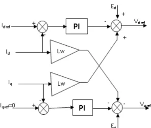
It is possible to order independently the components of the current id and iq by action on hd and hq, thus, it is simple to design the controllers. The principle of the decoupled controller is shown in Fig 5.
(5)
(6)
(7)
Fig .5: Decoupled controller
3.2 DC voltage regulation: A. PI controller:
The controller in the external control loop of the PWM rectifier is used to regulate the DC voltage side and to generate the magnitude of the reference line current which will be multiplied by the dc voltage to obtain the reference of the instantaneous active power to have the current reference Idref [5][7].
To have unity power factor condition, the Iqref current must be equal to zero [8][10]. The regulation function is ensured by a PI controller as shown in Fig .6:
Fig.6: DC voltage regulation with PI controller. The expression of the Pref active power is to obtained by the following expression: pref = vdc ∗ idref
Where Kp and Ki are the proportional and integral controller gains respectively. To determine the parameters of the PI controller, we make the following mathematical development. The relationship between the
power absorbed by the capacitor and the output voltage can be written as
pref =dtd �C ∗ Udc2 �
based on Laplace transformation, we can write Udc2 = pref ∗C∗S2
The transfer function of the PI controller can be expressed by
Kp+KS =i 1 + τSS ∗ T i
The transfer function of the closed loop system is given by F(S) = ω0∗ (1 + τ) S2+ 2ε0ω0S + ω0 With: ω0= � 2 CTi and: ε0= τ �2CTi
After calculation; we find Kp =Tτi and: Ki =T1i
B. Fuzzy controller:
For a good performance of the DC voltage control, in particular in the case of change of DC reference voltage level, the PI controller is replaced by a fuzzy controller
The principal scheme of this control is shown in fig.7
Fig .7: DC voltage regulation with FUZZY controller
The new control structure of the DC voltage preserves the same model adopted when the PI controller was used. These parameters are adjusted in real time according to the disturbance which increases. It is a question of associating the fuzzy regulator output to the proportional and integral actions of the control signal. The fuzzy regulator uses two inputs: The first input is the error between the reference and the measured value of the DC voltage. The second one represents the
(8)
(9)
(10)
(11)
variation of this error. These two signals are expressed by [5][8][10]:
ε(k) = vdcref(k) − vdc(k)
∆ε(k) = ε(k) − ε(k − 1)
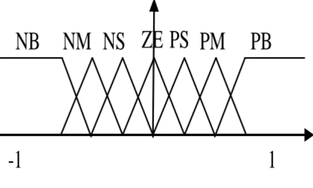
The membership functions representing the input and the output variables are given by Fig 8:
Fig .8: Membership functions of the input and the output variables
NB: Negative Big; NM: Negative Medium; NS: Negative Small; ZE: Zero; PB: Positive Big; PM: Positive Medium; PS: Positive Small.
Fuzzy rules are gathered in an inference matrix shown in Table2
Table.2 Fuzzy rules
4 . Simulation and discussion:
To validate the effectiveness of the control strategy studied in this paper, a digital
simulation was carried out under MATLAB/SIMULINK environment.
The DC voltage control system is tested as well as the VOC method following a DC voltage step variation occurring at t=0.5s from 250V to 300V.
The effectiveness of the DC voltage fuzzy control is illustrated by Fig.6. We can see that the system became more stable and more robust than we used a PI regulator. In this figure the overshoot completely disappears and the response time is reduced.
The system parameters studied in this paper are given in Table.3.
Table.3 System parameters
Fig.9. Control system step response (Vdcref =250 to 300 V)
NB NM NS ZE PS PM PB
-1
1
0 0.1 0.2 0.3 0.4 0.5 0.6 0.7 0.8 0.9 1 -50 0 50 100 150 200 250 300 350 400 Time(S) V ol tage( V ) PI Controller FUZZY Controller Vdcref(13)
Fig.10.Instantaneous active power Fig.10 show that when the DC voltage reaches the new reference value, the active power and consequently the line current increase. For the fuzzy controller, the power increase is limited. This avoids dangerous over currents for the system operation.
To compare the PI and the fuzzy controllers the harmonic spectrums of the current are given in Figs 12 and 13. It is shown that the fuzzy controller is better than the PI controller as far as the harmonic content is concerned (THD= 2,5 with a fuzzy controller compared to 3, 3 with a PI controller).
Fig.11. Line voltage and line current .
Fig.12 Harmonic spectrum and THD of the current with a fuzzy controller.
0 0.1 0.2 0.3 0.4 0.5 0.6 0.7 0.8 0.9 1 -0.5 0 0.5 1 1.5 2 2.5x 10 4 temps(S) P o w e r(W ) FUZZYController PIController 0.6 0.65 0.7 0.75 0.8 0.85 0.9 0.95 1 -500 -400 -300 -200 -100 0 100 temps(S) t ens i on& c our ant ( V & A ) 0.74 0.75 0.76 0.77 0.78 0.79 0.8 -100 -50 0 50 100 temps(S) t ens i on& c our ant ( V & A ) Va Ia PIcontroller IaFUZZYController 0 5 10 15 20 25 30 35 40 45 50 0 0.1 0.2 0.3 0.4 0.5 0.6 0.7 0.8 0.9 1 THD(%)= 2.5862 Rang(h) pu
Fig.13 Harmonic spectrum and THD of the currentt with the a PI controller.
5. Conclusion:
In this paper, we presented a control strategy for a PWM rectifier. It concerns the use of the voltage oriented control using two types of controllers a conventional PI controller and a fuzzy controller.
Simulation results have proven excellent performance of the proposed VOC based on FUZZY controller scheme which is much better than conventional VOC based on a PI controller. The performances are better both in transient and steady state conditions. Moreover, nearly almost sinusoidal waveforms of input currents are successfully achieved and guarantee a good regulation of the output voltage with a power factor near to unity.
Reference
[1] S. Vazquez, J. A. Sanchez, J. M. Carrasco, J. I. Leon, E. Galvan, A model-based direct power control for three-phase power converters, IEEE Transactions on Industrial
Electronics, 55(4),2008, 1647-1657
[2] C. X. Chen, Y. X. Xie, Direct power control of voltage source rectifier [C],
Proceedings of the 29th Chinese Control Conference, Beijing, 2010, 5003-5006
[3] Liwei Zhang , Guoqiang Zheng , Jishun Li Direct Power Control Strategy of Three-phase PWM Rectifier, Journal of Information &
Computational Science 10:9 (2013) 2807 2813
[4] Graziella Giglia, Marcello Pucci “Comparison of Control Techniques for Three-Phase Distributed Generation Based on VOC and DPC” Institute on Intelligent Systems for
the Automation, Palermo – Italy
I.S.S.I.A.-C.N.R..
[5] Abdelhafid SEMMAH, Ahmed MASSOUM, Habib HAMDAOUI, Patrice WIRA ,Comparative Study of PI and Fuzzy DC Voltage Control for a DPC- PWM Rectifier, Electrical Review, ISSN 0033-2097, R. 87 NR 10/2011.
[6] Sylvain LECHAT SANJUAN, Voltage Oriented Control of Three‐Phase Boost PWM Converters Design, simulation and implementation of a 3‐phase boost battery Charger, Department of Energy and
Environment Division of Electric Power
Engineering chalmars university of
technologie Göteborg, Sweden, 2010.
[7] Bhanu Priya K, Dr. Rama Rao P.V.V,fuzzy based three phase voltage source PWM rectifier for rapidily varying active load,
International Journal of Advanced Research in Electrical, Electronics and Instrumentation Engineering, An ISO 3297: 2007 Certified
Organization Vol. 2, Issue 10, October 2013 [8] J. Lamterkati1, M. Khafallah2, L. Ouboubker ,Comparison of PI and Fuzzy logic DC-Link Voltage Controller for DPC PWM-Rectifier, International Journal of Enhanced
Research in Science Technology & Engineering, ISSN: 2319-7463 Vol. 3 Issue 4,
April-2014, pp: (321-332), Impact Factor: 1.252
[9] Daniel Castro Carmona, Javier Fernández Mandiola, Design and Implementation of a Three-Phase Boost Battery Charger with PFC using CompactRIO Control System,
Department of Energy and Environment Division of Electric Power Engineering
chalmars university of technologie Göteborg, Sweden, 2012
[10] A Bouafia F Krim, A fuzzy-logic-based controller for three-phase PWM rectifier with unity power factor operarion, J.Electrical
Systems 4-1 (2008): 36-50. 0 5 10 15 20 25 30 35 40 45 50 0 0.1 0.2 0.3 0.4 0.5 0.6 0.7 0.8 0.9 1 THD(%)= 3.3006 Rang(h) pu