• Aucun résultat trouvé

Active tremor control of human motion disorder

N/A
N/A
Protected

Academic year: 2021

Partager "Active tremor control of human motion disorder"

Copied!
142
0
0

Texte intégral

(1)

Active Tremor Control of Human Motion Disorder

by

Gary Ellis Hall

B.S., Mechanical Engineering

University of Rochester, May 1998

Submitted to the Department of Mechanical Engineering

in partial fulfillment of the requirements for the degree of

Master of Science in Mechanical Engineering

at the

MASSACHUSETTS INSTITUTE OF TECHNOLOGY

June 2001

@ Gary Ellis Hall, 2001. All rights reserved.

The author hereby grants to MIT permission to reproduce and distribute publicly paper

and electronic copies of this thesis document in whole or in part.

Author ...

...

Certified by...

Certified by...

Accepted by ...

...

. ...

.

..

...

Depaf/ment of Mechanical Engineering

May 22, 2001

... ... ...

Kenneth W. Kaiser

Senior Technical Staff

The Charles Stark Draper Laboratory, Inc.

Thesis SuDervisor

Mandayam A.'Srinivasan

Principal Research Scientist & Lecturer

Department of Mechanical Engineering

Thes*

rvisor

...

. .... ... a ~

...

Ain A. Sonin

MASSA INSTITUTE Chairman,

Committee on

Graduate Studies

Department

of

Mechanical Engineering

JUL 16 2001

(2)
(3)

Active Tremor Control of Human Motion Disorder

by

Gary Ellis Hall

Submitted to the Department of Mechanical Engineering on May 22, 2001, in partial fulfillment of the

requirements for the degree of

Master of Science in Mechanical Engineering

Abstract

All humans are subject to a physiological phenomenon known as tremor, which introduces

un-intended, relatively high-frequency movements into various parts of the body. These unintended movements serve to limit human motor performance with respect to normal human performance (for cases in which tremor is severe), and with respect to tasks that require "superhuman" per-formance (for cases in which not even normal tremor is tolerable). For example, the elderly often experience reduced motor control to the point where they can not eat. Similarly, surgeons per-forming eye surgery must have very little tremor to enable them to operate on the small anatomy of the eyes. In both cases, a motion disorder known as essential tremor can be the cause of the insufficient level of human motor performance.

Current treatments for tremor disorders such as essential tremor include a small set of extremes (brain surgery versus doing nothing), with very little "middle ground." A device that could easily be placed onto the body and removed when not needed could fill this niche nicely. Due to the potential for high performance and portability, a new type of tremor stabilizer is proposed that uses a proof mass actuation scheme. This prototype device intended to attenuate human essential tremor along two translational axes was designed, constructed, and tested. Mechanical design, dynamics, and control systems modeling were performed, and the end device built to specifications.

A shaker and experimental mount were constructed to artificially simulate tremor, and all data

were gathered using this setup. The prototype demonstrated a 4:1 reduction in simulated tremor acceleration power from open- to closed-loop operation, as well as a 2:1 reduction in simulated tremor amplitude from open- to closed-loop operation. Medical personnel at Massachusetts General Hospital have suggested that this level of tremor attenuation would be helpful for their patients.

Results were limited to vibrations along one of the two translational axes. Limitations of the prototype are discussed, as well as design strategies to improve performance in future work. Thesis Supervisor: Kenneth W. Kaiser

Title: Senior Technical Staff

The Charles Stark Draper Laboratory, Inc. Thesis Supervisor: Mandayam A. Srinivasan Title: Principal Research Scientist & Lecturer Department of Mechanical Engineering

(4)
(5)

Acknowledgments

I don't know where to begin when it comes to writing the acknowledgements of this thesis. So many people and entities have assisted me along the path to completion of this work that I feel as if I am really completing our thesis. The largest group project in which I have taken part. I'll do the best I can to include everyone.

I would like to thank Professor Mandayam A. Srinivasan, for agreeing to take a slice of his already busy schedule and devote this time to me. I look forward to hearing of future discoveries in the Touch Lab at MIT.

To Draper Laboratory, I would like to extend thanks. As a graduate student, I was well provided-for within Draper, both in terms of material assistance, and access to expert personnel. Numerous people within Draper deserve my regards. To Mitch Hansberry, I would like to extended my gratitude for the excellent work he did in preparing drawings and designs for this thesis. Mitch dispatched all of the bizarre design requests I sent his way quickly and professionally. A special thank you goes out to Tony Emberly and Bob Visser, who tolerated the introduction of a petty thief disguised as a graduate student into their lab. I promise I'll return all of your equipment. Thanks to Bob Faiz, who introduced many useful ideas that were incorporated into the later design revisions of the prototype. Jay Courturier, of Draper Media Services, took nearly all of the photographs seen in this thesis. Thank you, Jay, for you fast and excellent work.

Kenneth Kaiser deserves my greatest thanks. Ken has guided me through this work, found funding for my project, patiently pointed out that my prototypes were not working because wires were reversed or something important was left ungrounded, and survived the wave of thesis drafts I have thrown his way. At the same time, he also provided me with help in all of the classes I've taken. In our frequent discussions, he has also taught me a lot about life, and I will take his perspectives on many issues with me when I leave. I look forward to learning of Ken's progress in future tremor control projects.

I feel a special need to thank Donna Jean Kaiser. She selflessly provided a wonderful source of support at a crucial time in my life. I also learned a great deal from her, both technically and about life, and continue to look to her life and accomplishments as a source of inspiration. Also, Donna has eased the life of this graduate student with frequent trips to Cambridge for food.

Last, but not least, I would like to thank my family. My parents and brother have always loved and supported me, and I'm fortunate to be able to crash at my grandmother's house (with all of

(6)

my laundry) every time I head home for a break. It is easy to look at this thesis and see the pages, the equations, the plots. It is slightly more difficult to see the effort that went into the creation of these things. It is nearly impossible to know that the existence of this thesis is due to the influences of these special people.

This thesis was prepared at The Charles Stark Draper Laboratory, Inc., under Internal Company Sponsored Research Project 13058, Tremor Control.

Publication of this thesis does not constitute approval by Draper or the sponsoring agency of the findings or conclusions contained therein. It is published for the exchange and stimulation of ideas.

(7)

This thesis is dedicated in memory of

(8)
(9)

Contents

1 Introduction

1.1 O verview . . . .

1.2 Previous W ork . . . . 1.3 Proposed Active Tremor Control System Description . 1.3.1 Concept of Correcting Forces . . . . 1.3.2 Concept of Acceleration Feedback . . . . . . . 1.3.3 Concept of Tuned Damping . . . ... 1.3.4 Concept of Shared Proof Mass . . . . 1.4 Thesis Scope . . . . 2 Preliminary Analysis and Modeling

2.1 Overview . . . . 2.2 Analysis Guidelines from Literature 2.3 Sensor Selection . . . ... 2.4 Actuator Selection . . . . 2.5 Summary of Analysis and Modeling

3 Mechanical Design

3.1 Overview . . . . 3.2 Wrist/Actuator Mount . . . . 3.3 Linear Bearings . . . . 3.4 Proof Mass Structure . . . . 3.5 Sensor Mounting . . . . 3.6 Resultant Prototype Characteristics

19 . . . . 19 . . . . . . . 21 . . . . . . . . . 23 . . . . . 24 . . . . 25 . . . . 26 . . . . 28 . . . . 29 31 . . . . . . . . 3 1 . . . . . . . . 31 . . . . 36 . . . . . . . I . . 3 9 . . . . 47 49 . . . . . . ... . . . . 4 9 .. . . . . 5 1 . . . .. . . . . 5 3 . . .. . . . .. I . . . . 5 8 . . . .. . . . . . . . . 6 0 . .. . .. . . . . . . . . . . 6 1

(10)

4 Control System Design

4.1 O verview . . . . 4.2 Lumped-Parameter Model . . . . 4.3 Control Electronics Layout . . . . 4.4 Control Electronics Packaging . . . . 4.5 Control Loop Tuning . . . .

4.5.1 Determination of Absolute Controller Proportional Gain 4.5.2 Determination of Absolute Controller Derivative Gain

5 Experimental Results

5.1 O verview . . . . 5.2 Qualitative Results: Perceived Tremor Reduction . . . . 5.3 Quantitative Results . . . . 5.3.1 Baseline Results . . . . 5.3.2 Levitated Results . . . . 5.3.3 Levitated and Tremor Compensated Results . . . .

6 Conclusions and Suggestions for Future Work

6.1 C onclusions . . . . 6.2 Suggestions for Future Work . . . .

A Mechanical Drawings of Parts Used

B Analyses Utilized in Controller Tuning

B .1 O verview . . . . B.2 System Description . . . . B .3 Special C ases . . . . B.4 Determination of Controller Types . . . . B.5 Attenuation Sensitivity Function . . . . B.6 "Shaping" of the Attenuation Sensitivity Function . . . .

67 . . . . 67 . . . . 67 . . . . 69 . . . . 76 . . . . 80 . . . . 82 . . . . 84 91 . . . . 91 . . . . 92 . . . 93 . . . 96 . . . 97 . . . 100 105 105 107 109 121 121 121 123 126 131 133

(11)

List of Figures

1-1 Free body diagram of single axis proof mass stabilizer. . . . . 24

1-2 Free body diagram of single axis proof mass stabilizer with acceleration feedback. . . 25

1-3 Proof mass stabilizer with acceleration feedback and tuned damping. . . . . 27

1-4 Diagram of proposed active tremor control system. . . . . 29

2-1 Photograph of the PCB Piezotronics 3701 accelerometers. . . . . 37

2-2 Photograph of the Analog Devices ADXL105 accelerometers . . . . . 38

2-3 Photograph of the Analog Devices ADXL202 accelerometers. . . . . 39

2-4 A 2 degree of freedom model to aid in actuator specification. . . . . 41

2-5 Block diagram of the 2 degree of freedom model analyzed on Simulink. . . . . 43

2-6 Plot of actuator stroke x versus m2 for a variety of frequencies. . . . . 45

2-7 Photograph of BEI LA1O--12-027A voice coil assembly, single core assembly, and single coil assem bly. . . . . 47

3-1 Photograph of the wrist/actuator mount of the tremor controller. . . .... . . . . . 51

3-2 Photograph of the tremor control prototype in four different stages of articulation. . 53 3-3 Photograph of Del-Tron model D-1 ball slide used in the fabrication of the prototype. 55 3-4 Schematic of unmodeled dynamic that lead to structural resonance . . . . 56

3-5 Schematic of parts added to eliminate structural resonance. . . . . 57

3-6 Photograph of parts added to eliminate structural resonance. . . . . 57

3-7 Photograph of the proof mass frame. . . . . 59

3-8 Photograph of a Schaevitz 250-MHR LVDT sensor inserted into an ABS mounts with core in the background . . . . . . . . . 62

3-9 Photograph of completed assembly, front view . . . . . . . . . 62

(12)

3-11 Photograph of completed assembly, left view. . . . . 3-12 Photograph of completed assembly, right view. . . . . 4-1 4-2 4-3 4-4 4-5 4-6 4-7 4-8 4-9 4-10 4-11 4-12 of K GD. ... . ... ...

4-13 KGD values obtained by dividing the data from Figure 4-12. . . . 4-14 KGD values obtained by curve fitting method. . . . .

Lumped parameter model of the resonant system .. . . . . Block diagram of the control system electronics, without power supplies. . . . . Inverting summer circuit schematic for the conversion to a MISO system. . . . . Preamplifier circuit schematic for the PCB 3701 accelerometers. . . . . . Bode plot of the response of the PCB 3701 accelerometer preamplifier circuits. . . . Photograph of the equipment mounted inside of the Pelican 1620 case. . . . . Photograph of the equipment mounted inside of the Pelican 1620 case, detailing DMC-2040, power supplies, and power amplifiers. . . . . Photograph of the equipment mounted to the door of the Pelican 1620 case. . . . . . Bode plot of SA with PIDP controller. . . . . Unprocessed data output of the Galil DMC-2040 .. . . . .

KGP values obtained by dividing the data from Figure 4-10. . . . .

LVDT signal, LVDT signal derivative, and motor command used in the determination

Photograph of tremor control prototype in test stand, front view. . . . . 94

Photograph of tremor control prototype in test stand, back view. . . . . 95

Plot of motor rotation frequencies versus excitation voltage. . . . . 96

Baseline acceleration of device under influence of shaker motor. . . . . 97

Power Spectrum Density of acceleration under influence of shaker motor . . . . . 98

Levitated and non-levitated PSD. . . . . 99

Acceleration and actuator force of x-axis control loop. . . . 101

Acceleration and actuator force of x-axis control loop, in detail. . . . 102

Open- and closed-loop PSD results. . . . 103

Open- and closed-loop displacement. . . . 104 A-1 Mechanical drawing of the SLA wrist mount. . . . .

A-2 Mechanical drawing of the accelerometer standoff. . . . .

110 111 63 64 68 70 73 74 74 77 78 79 81 83 85 87 88 89 5-1 5-2 5-3 5-4 5-5 5-6 5-7 5-8 5-9 5-10

(13)

A-3 Mechanical drawing of the LVDT mounting bracket. . . . 112

A-4 Mechanical drawing of the adapter plate between the actuator and ball slide. . . . . 113

A-5 Mechanical drawing of the proof mass guide pin mounting through the accelerometer. 114 A-6 Mechanical drawing of the slide block. . . . 115

A-7 Mechanical drawing of the proof mass frame... . . . . . . . . 116

A-8 Mechanical drawing of tungsten weight. . . . 117

A-9 Mechanical drawing of Teflon bushing. . . . 118

A-10 Mechanical drawing of the shield . . . . . . . 119

B-1 Block diagram of the system analyzed using classical controls techniques. . . . 122

B-2 Possible system performance with a transfer function similar to Equation B.11. . . . 124

(14)
(15)

List of Tables

1 Variables used in this thesis, the variable units, and a description of the variable. 2.1 Worst-case tremor amplitudes and accelerations at various frequencies computed

using Equation 2.4. . . . . 2.2 Disturbance force values to create tremor amplitudes seen in Equation 2.4 computed

using two different methods. . . . . 2.3 Mass-stroke product for the data points in Figure 2-6. . . . . 3.1 Mass breakdown of parts of the tremor controller assembly. . . . . 3.2 Cost breakdown of parts of the tremor controller prototype. . . . . 4.1 Pin assignments on the 25-pin tremor controller connector.

4.2 Connections to ICM-2900 interconnect module. . . . . 4.3 Mean KGp values for several different sensor inputs . .

5.1 Data acquisition channels. . . . . . . .

. . . . 71 . . . . 72 . . . . . . . . 85 . . . . . . 92 . 17 33 44 45 65 66

(16)
(17)

Definition of Symbols

Symbol A x1 X2 x 'mi m2 I k1 k2 bi b2 KAP KAD KAI KLP KLD KLI KGP KGD Gp1 GP2 GL GA GD .7 SA W Units length length length length mass mass mass-length2 length force/length force/length mass/time mass/time Volt/Volt

(Volt .time) /Volt Volt/ (Volt.time) Volt/Volt

(Volt .time) /Volt Volt/ (Volt.time) Volt/Volt

(Volt -time) /Volt time2 /mass time2 /mass

time-1

Table 1: Variables used in this thesis, the variable units, and a description of the variable. Description

Amplitude of oscillations at the wrist. Position of wrist/hand.

Position of proof mass.

Distance between wrist and proof mass, x = x2 - Xi.

Observed inertia of entire forearm and hand as experienced at wrist. Inertia of proof mass.

Rotational inertia of forearm about the elbow. Length of forearm from elbow to wrist.

Spring constant of coupling between the body and wrist. Spring constant of coupling between wrist and proof mass. Damping constant of coupling between the body and wrist. Damping constant of coupling between the wrist and proof mass. Proportional feedback gain of accelerometer loop.

Derivative feedback gain of accelerometer loop. Integral feedback gain of accelerometer loop. Proportional feedback gain of LVDT loop. Derivative feedback gain of LVDT loop. Integral feedback gain of LVDT loop.

Proportional feedback gain of the Galil DMC-2040. Derivative feedback gain of the Galil DMC-2040. Transfer function of ml.

Transfer function of m2.

Transfer function of LVDT control loop. Transfer function of accelerometer loop.

Transfer function of plant acted on by disturbance. Damping coefficient of system.

V/1 +m 2/mi/V1 + KAP

Attenuation sensitivity function. Natural frequency.

(18)
(19)

Chapter 1

Introduction

1.1

Overview

Tremor is a physiological phenomenon found in all human beings. It is typified by relatively low amplitude, relatively high frequency (in the 4-12 Hertz range), unintended movements of various parts of the body. All people deal with at least some tremor in their day to day lives with few consequences. For example, the beating of an individual's heart produces what are deemed

cardioballistic disturbances in the motion of the individual. We are all subject to these disturbances,

yet almost none of us suffer any ill effects [10]. In certain cases, particularly in those people with neurological disorders, tremor can be a debilitating condition that erodes quality of life. An effective means of tremor attenuation could therefore improve the lives of those adversely affected by tremor. The medical community views tremor as both a symptom of other ailments and as an ailment in itself. Physical tasks, such as eating, drinking, reading, walking, and proper personal care are made more difficult (and sometimes impossible) by the interference of tremor. In fact, tests used within the medical community to gauge the severity of tremor often assess the ability of a patient to accomplish these simple tasks [7, 16, 17, 25]. The majority of the medical literature deals with analysis and modeling of the hands, fingers, and lower forearms of those with tremor, since unwanted motion within these body parts contributes largely to the decrease in quality of life. Thus, it would seem as though stabilization of the hands and/or fingers would provide one of the biggest benefits to those affected by pathological tremor.

In addition to having negative medical consequences, human tremor limits the attainable perfor-mance of a wide variety of man-machine systems. Effects of these limitations range from annoying, as in the case of those suffering from drug-induced tremor attempting to perform precision

(20)

mechan-ical work, to potentially life-threatening, as in the case of surgeons with tremor. As society becomes more and more technologically advanced, it is common for the devices with which humans interact to become capable of higher accuracy than the people interacting with them. For this reason, the unintended motion introduced by tremor is becoming a limiting factor in the performance of many modern systems.

Attempts at controlling human tremor have begun to appear in the marketplace. Binoculars and camcorders that actively attenuate tremor of the operator are currently commercialized. While these systems work well in controlling tremor, the modality of tremor control is of limited utility. These systems are concerned primarily with the removal of tremor noise from optical data. As such, means to remove tremor information are all that are required. Thus, while the camcorder or binoculars are still moving due to the tremor of their operators, the active systems inside are

virtually removing tremor from the imagery captured by the device. In the application studied in

this thesis, the physical object (which would be attached to an individual) must not be physically moving for a real benefit to exist.

Many attempts to control tremor using passive technologies have been undertaken, with limited results [23]. This thesis was motivated by a desire by the experimenters to implement current off-the-shelf (COTS) technology to actively control tremor. Some classic works on the subject of active versus passive control of oscillating systems have clearly demonstrated the superiority of actively controlled systems to passively controlled systems [9]. Den Hartog demonstrated that a pair of small hydroplanes on the hull of a ship could much more efficiently stabilize the vessel in rough waters than a variety of passive technologies. It is the author's belief that a similar active system, constructed with many of the same design philosophies as the oscillating ship example in Reference [9], will yield a similar payoff in terms of tremor attenuation per unit mass of, power input to, and size of the device.

Discussions between the experimenters and Drs. Alice Flaherty and David Standaert at the Mas-sachusetts General Hospital Department of Neurology indicated that efforts at controlling tremor would be best directed at a motion disorder known as essential tremor. Essential tremor (ET) is a condition typified by an uncharacteristically large tremor in otherwise healthy patients that is controlled by a "central oscillator" within the patient's central nervous system [13]. Unlike Parkin-sonian tremor, which is attenuated as the patient concentrates on the task at hand, essential tremor is always present. A system designed to control the characteristics of Parkinsonian tremor would therefore achieve little more than a cosmetic fix when the stabilized limb was not in use. A cosmetic

(21)

fix is indeed very important, but the author is more concerned with the impairment suffered by those with debilitating tremors. A system designed to control essential tremor would help those otherwise disabled by tremor perform normal tasks.

1.2

Previous Work

The medical literature regarding tremor is well developed and provides a good background of the various characteristics of tremor [13]. Attempts to understand and model tremor have taken the form of a wide range of activities, from one- and two-degree of freedom lumped parameter me-chanical models to more detailed models that describe complex neurological systems and processes [10, 11, 13, 18]. Unfortunately, experts in the field of tremor admit that there exists almost no knowledge of the physiological systems that cause tremor [10]. As such, medical treatments for tremor range from nothing in the case of mild or weak tremors that do not interfere with everyday activities, to deep brain implants and other brain surgeries for the most severe cases of tremor. It would seem as though a mechanical treatment to suppress tremor could help "fill the gap" between these extremes in treatment. Such a mechanical treatment could help individuals who don't have tremors severe enough to warrant surgical procedures, but who do have tremors severe enough to interfere with routine activities. Medications to control tremor are frequently used, but are not particularly effective and are plagued with side effects. In any event, it is likely that some form of simple mechanical stabilization is superior to the added cost and potential side effects found with prescribing medication for the patient. Fortunately, this thesis can proceed knowing only the mechanical characteristics of tremor.

Previous attempts at mechanical tremor reduction have relied heavily on passive technologies. Viscous damping, added inertia, and gyroscopic stabilization have all been attempted [12, 23]. Only limited success has been obtained largely due to the fact that these methods seek to attenuate all motion, rather than just unintended motion. In other words, it is not very useful to a tremor patient to have a steady hand that has severely limited mobility, which would be the case for these other mechanical stabilization schemes. Other problems encountered with passive technologies have included the increased muscle strength created with extended use of the dissipating element, and fatigue associated with constantly "fighting" the passive device [23]. A well-designed tremor reduction system should counteract only unintended motions, thereby going almost unnoticed by the user.

(22)

Data regarding the amplitude, velocity, acceleration, and dominant frequencies of tremor are sought by the author. Luckily, these data are readily available in a number of resources [10, 11, 20]. In particular, a characterization of tremor as it appears within movement disorders such as essential tremor is sought. The body of literature detailing tremor generally agrees that the prominent frequencies of the tremor motions are in the range of 4-12 Hertz, depending on a wide range of variables (i.e., the physiological cause of the tremor, the location of the tremor within the body, the age of the patient, the recent activity level of the patient, medications taken by the patient, etc.). Typical tremor characteristics for the hands and fingers are in the range of 8-12 Hertz, with maximum amplitudes for severe tremor in the range of 40 mm (1.57 inches) [11].

As mentioned previously, some commercial stabilization systems have found their way to the marketplace. For example, Canon USA, Inc. manufactures and markets an entire product line of image stabilizing components. The components include binoculars, telescopes, and telephoto lenses for cameras. Again, these technologies do not perform a physical stabilization of the system. The imagery the device is designed to capture is the only entity that benefits from tremor removal [3]. These systems, therefore, are not well-suited to situations in which the physical vibrations from a complete man-machine system must be removed.

Some experimental work has been undertaken at the Carnegie Mellon University Robotics Institute in an effort to perform a physical stabilization of a scalpel blade used in eye surgery [21, 22]. This work utilized closed-loop control of piezoceramic actuators to remove tremor motion from the blade of the instrument. Work such as this is pertinent to this thesis, but the system later proposed aims to be more versatile. This thesis also proposes the use of a proof mass stabilizer, as opposed to direct movement of the object to be stabilized. While the preliminary results from the tremor-controlled scalpel look promising, this is but one application of vibration control technology to a wide range of existing problems. It is possible that the scalpel could be adapted into a wide range of other tremor-controlled objects (such as a spoon, knife, fork, or pen), but each of these devices would need to be independently designed, constructed and purchased. This would no doubt increase the costs associated with tremor control for the patients. It is hypothesized that building a tremor controller for the entire hand would allow the other objects to be used with only one system. This versatile system could, it is hoped, allow a tremor patient to buy one device that could be used in conjunction with other handheld objects. The cost of stabilization would be driven by just one object rather than several.

(23)

Labo-ratory, Inc.1 in the area of active stabilization of small arms for the United States military. Sniper rifle design and manufacturing practices have brought these weapons to a point at which they are capable of higher accuracy than their human operators [6]. Sniper rifles are capable of higher performance than their human operators under optimal shooting conditions, and performance of the man-machine sniper and rifle system is only degraded once soldiers are exposed to the rigors of field conditions (i.e., cold temperatures, anxiety, malnutrition, sleep deprivation, etc.). The Defense Advanced Research Projects Agency2 (DARPA) has therefore funded research to actively reduce the effects of human tremor on the accuracy of sniper rifles. This research has been developed to the successful demonstration of an alpha prototype, and research into the technology is continuing. Again, though, this application of tremor control aims to attenuate one type of motion in one type of system. This thesis aims for a more generic solution to tremor.

Some studies also appear to examine the relationship between tremor and excitations to a limb with tremor [11, 18]. In these studies, a torque motor was utilized in order to try to influence the phase of the tremor. Results demonstrated that the phase of some forms of tremor could be "reset" through mechanical influence. While these studies seem to hint at the subject of influencing tremor using mechanical actuation, closed-loop tremor reduction is never introduced. Also, these studies focused more on the modification of the tremor phase rather than the tremor amplitude. A change to the tremor phase is of little practical use in this thesis.

1.3

Proposed Active Tremor Control System Description

This thesis will serve as the first investigation into an active control system intended to perform tremor attenuation from a human hand and wrist. More specifically, this thesis details the study of a "wrist cuff" stabilizer intended to remove translational tremor along two axes from an individual with essential tremor.

The subsections that follow will develop the concept of a proof mass stabilization system, as well as its particular application in this thesis. The theory of operation of a proof mass stabilizer is often misunderstood, and for this reason great care is taken to describe the system that will be developed in this thesis. Subsection 1.3.1 begins the explanation with a description of how a proof mass stabilizer applies correcting forces. Subsection 1.3.2 continues the development with an

1555 Technology Square, Cambridge, MA 02139. 23701 North Fairfax Drive, Arlington, VA 22203-1714

(24)

proof

mass

actuator reaction force

actuator

tremor correcting force

stabilized wrist

(in cross-section)

tremor force

Figure 1-1: Free body diagram of single axis proof mass stabilizer.

explanation of the specification of correcting forces using acceleration feedback. Subsection 1.3.3 adds a description of the tuned damper. Lastly, Subsection 1.3.4 outlines the concept of using one shared proof mass for two axes of operation.

1.3.1 Concept of Correcting Forces

The operational paradigm of the proposed system is the application of correcting forces to a moving wrist via a proof mass actuation scheme, as shown in the free body diagram of Figure 1-1. A proof mass stabilizer is generally used in situations in which the system that needs stabilization must be freely moving, and therefore cannot be attached to a rigid structure capable of exerting reaction forces. The system therefore receives correcting forces by reacting against a proof mass, or an inertia, rather than a rigid reaction surface. A reaction mass is attached to an actuator, and when the actuator exerts a tremor correcting force, the actuator reaction force is exerted on the proof mass. The end goal of a proof mass stabilization scheme is to remove oscillations of the system one wishes to stabilize by applying forces between the system and the proof mass. The inertia of the proof mass limits the acceleration of the proof mass (if the system is properly designed), and the system requiring stabilization receives correcting forces to counteract the oscillations. This concept is illustrated in Figure 1-1.

(25)

proof

mass

t

actuator reaction force

feedback f --- force

---- actuator

controller commands

signals tremor correcting force

accelerometer stabilized wrist

(in cross-section)

tremor force

Figure 1-2: Free body diagram of single axis proof mass stabilizer with acceleration feedback.

it must be able to communicate with other systems on Earth, which requires pointing the antenna of the satellite in the proper direction. A satellite in orbit does not have any structure against which to push so that it can turn itself. Instead, the satellite carries reaction wheels mounted on motors, and it is these massive reaction wheels that are spun, which results in equal and opposite torque application to the satellite.

Figure 1-1 does not tell the whole story, however. Two questions remaining are, "How does the system know when to apply a tremor correcting force, and how large should the tremor correcting force be?" Subsection 1.3.2 develops the answers to these questions.

1.3.2 Concept of Acceleration Feedback

Figure 1-2 is identical to Figure 1-1, except for the addition of controller electronics and an ac-celerometer. Section 1.3.1 makes mention of the fact that the tremor forces in Figures 1-1 and 1-2 are not constant. In fact, tremor forces are time-varying forces that approximate sinusoids, but can have a wide range of frequencies and magnitudes. Thus, a means to determine when to apply a tremor correction force is needed, as is a means to determine how large a tremor correction force to apply.

(26)

force acting on a wrist will lead to an acceleration of the wrist via Newton's 2nd Law

F = ma, (1.1)

in which F is the force acting on the mass m, producing an acceleration a [14]. If an accelerometer were attached to the accelerating wrist, as in Figure 1-2, then the acceleration resulting from the action of the tremor force on the wrist could be sensed. The signal from the accelerometer can now be used to answer the questions of when to apply tremor correcting forces and how much tremor correcting force to apply.

To answer these two questions, we pass the signal from the accelerometer to controller elec-tronics, as shown in Figure 1-2. These electronics will receive acceleration signals from the ac-celerometer, and then send commands to the actuators that will produce tremor correction forces. If the accelerometers sense no acceleration, the controller electronics will send no commands to the actuators. If the accelerometers sense a moderately-sized, positive (upward) acceleration caused by a positive (upward) acting tremor force, the controller electronics will respond by instructing the actuators to produce a moderately-sized, negative (downward-acting) tremor correcting force. Conversely, if the accelerometers sense a large, negative (downward) acceleration, the controller electronics will respond by instructing the actuators to produce a large, positive (upward) tremor correcting force. Thus, the addition of accelerometers and controller electronics allow the system to become stabilized.

1.3.3 Concept of Tuned Damping

Subsection 1.3.2 provided an explanation of reducing tremor vibrations using an accelerometer and controller electronics. A second sensor can be added to the system to provide even better performance. A sensor that measures distance, in this case a linear voltage displacement transducer (LVDT) can also be added to the system to measure distance between the proof mass and the wrist. Addition of an LVDT is shown in Figure 1-3.

The LVDT is added to the system for the purposes of centering the proof mass against the ever-present forces of gravity. The actuators are limited in how far they can move the proof mass by their stroke lengths. As such, some means to instruct the actuators to hold the proof mass in a centered position is needed, so that the proof mass will be able to move up or down in response to the application of tremor correcting force by the actuator. In other words, if the proof mass

(27)

force commands

proof mass

actuator reaction force

LVDT

feedback signals controller

actuator

signals tremor correcting force

accelerometer stabilized wrist

(in cross-section)

tremor force

Figure 1-3: Proof mass stabilizer with acceleration feedback and tuned damping.

were not centered and ended up resting against the wrist, a command to apply an upward tremor correcting force would result in a downward actuator reacting force, which would not accelerate the proof mass since it is already in its "full down" position. Thus, an LVDT is added to the system to maintain an approximately centered position for the proof mass.

A side benefit of the presence of the LVDT is that the signals from the LVDT and the con-troller electronics can be used to create a tuned vibration absorber for the system. Tuned vibration absorbers function by addition of a spring-mass system to a vibrating system, such that the char-acteristics of the spring-mass system absorb energy from the vibrating system. The end result is that the added spring-mass system vibrates, leaving the system vibrating due to tremor with less energy, and a lower vibration amplitude. The theory of vibration absorbers is mature and well developed, as for example in [9].

Thus, the main components of a vibration absorber are a mass and a spring, and sometimes a damper. The spring provides a force in response to a displacement. So, if the spring is stretched, it attempts to contract to its original length. If the spring is compressed, it attempts to extend to its original length. The proof mass system mentioned so far already has a vibrating system (the wrist), a mass (the proof mass), and now it has a spring. The LVDT signals sense displacement,

(28)

and so can be utilized with the controller electronics to create an electronic spring. In other words, if the LVDT senses a "stretch" in the distance between the wrist and the proof mass, the controller electronics send a force command to the actuator to try to "unstretch" the electronic spring. In this way, an electronic spring can be made to link the wrist and proof mass.

A damper acts by providing a force in response to a velocity. In other words, the damper provides reaction forces when the ends of the damper are displaced with respect to one another in some time-varying manner. Again, the LVDT signals can be differentiated with respect to time to provide information regarding the velocity of the proof mass with respect to the wrist. The effect of this is to create an electronic damper, analogous to the previously detailed electronic spring.

Specification of appropriate controller feedback values will create an electronic spring and damper with the correct physical sizes. Details of selecting the actual feedback values will be presented later in this thesis.

1.3.4 Concept of Shared Proof Mass

The benefit of using a proof mass actuation scheme in an application like tremor control is that the system can be unconstrained in space. The proof mass actuation scheme does not require attachment to a wall or other structure, and so would allow the user unrestrained motion. Thus, the author envisions the device as one which could be worn by a user much as a wristwatch or a pair of eyeglasses, that function to enhance the life of the wearer while being as unobtrusive as possible. Unfortunately, the unconstrained nature of the device means that the individual wearing the device will have to support the entire weight of the device. There is an incentive to make the device as light as possible, while maintaining effectiveness of the proof mass stabilization system.

Figure 1-4 shows the system of Figure 1-3 extended to act in two directions. The device is now capable of counteracting tremor forces acting both vertically and horizontally. Along with this increased capability comes the need for a second proof mass. As previously mentioned, though, the goal is to make the system as light as possible. Thus, it would be beneficial to find a way to efficiently use the mass of the device.

One way to do this is to have both actuators share a common proof mass. In other words, the proof mass is free to move along two axes, vertical and horizontal. The benefit of this approach is that the system mass is effectively halved. The disadvantage is increased mechanical complexity from the mechanism needed to allow the actuators the flexibility to share the proof mass. Mechan-ical design of the prototype will encompass a number of innovative design features. In addition to

(29)

LVDT and accelerometer signals actuators proof mass LVDTs controller electronics servo wrist amplifiers (cross-section) x accelerometers axes of tremor motion actuator commands

Figure 1-4: Diagram of proposed active tremor control system.

the sharing of the proof mass, the proof mass will be designed such that the center of mass of the device is very close to the center of the wrist. The details of the mechanical design will become

apparent in Chapter 3.

1.4

Thesis Scope

This thesis proposes to model, design, construct, and test a system to physically remove two axes of translational tremor from the wrist/hand of an individual with essential tremor. As mentioned before, it is the author's belief that the greatest utility could be extracted by stabilizing the hands of those afflicted with severe tremor so that normal activities involving the hands can be performed. Stabilization of a hand can, in theory, allow the individual to properly eat, drink, and perform other manual tasks such as dialing telephones, without the assistance of caretakers or relatives. Thus, the design and construction of a prototype "wrist cuff" stabilizer is undertaken in this thesis.

Using information available in the literature, I hope to obtain the required specifications for sensors and actuators to attain the thesis goals. Once these specifications are obtained, a lumped-parameter system model will be constructed, and its performance analyzed. This will allow proper control system design to take place. Mechanical and electrical design of the modeled system will

(30)

follow, and the thesis will conclude with a qualitative and quantitative evaluation of the performance of the constructed system.

(31)

Chapter 2

Preliminary Analysis and Modeling

2.1

Overview

This chapter details the initial engineering study aimed at determining the feasibility of constructing a wrist-stabilizing tremor controller. An engineering study was performed in order to determine what types of tremors could be attenuated, what the system operation paradigm would be, and what types of sensors and actuators would be required.

It was decided that a proof mass stabilization scheme would best meet the engineering require-ments. Such a stabilization system would sense tremor motions, and then activate an actuator between the wrist and a proof mass. A correcting force would act on the wrist, with the inertia of the proof mass acting as the inertia against which the actuator would apply force. See Figure 1-3 for a schematic representation of the architecture of such a system.

2.2

Analysis Guidelines from Literature

In order to expedite the design and construction of the device, specification of the major components was begun as soon as possible. For example, the linear actuators could have had a lead time of up to four months if custom actuators were required or if a production actuator model were out of stock. Also, it was known that silicon micromachined accelerometers were only in development within Draper Laboratory, but were in production at Analog Devices. If custom accelerometers were needed, this would have also created a long lead time. Faced with delays such as these, the design of the device was begun in earnest. It was decided that the most critical components to specify would be those that absolutely had to be obtained from sources outside of Draper Laboratory. The

(32)

only parts for the prototype that had to be procured from outside sources were the sensors and actuators. Thus, the preliminary analysis presented in this chapter is that used to specify sensors and actuators for the thesis.

The design of the tremor suppression device had to have some starting point determined by the type of behavior we expected the system to exhibit. Since the thrust of this application was the modification of mechanical behavior, a logical starting point was a characterization of the mechanical behavior we wished to modify. Preliminary design studies were performed using tremor characteristics available from the literature. Assuming a very simple model of tremor motion, the displacement of the wrist/hand associated with tremor, xi, was approximated by the sinusoid

xi(t) = Asin(27rwt + #), (2.1)

in which A is the amplitude of the tremor displacement, w is the frequency of the tremor in Hertz, t is time in seconds, and

#

is the phase angle [9]. Indeed, data displaying essential tremor often appear to be sinusoidal in shape, so this model may not be as simplistic as it seems [11]. Furthermore, Elble and Findley define tremor as any involuntary, approximately rhythmic, and roughly sinusoidal

movement [10]. Thus, it would appear as though the model of hand tremor presented in Equation

2.1 was a respectable starting point. Taking the first and second derivatives of Equation 2.1 resulted in similar expressions for velocity and acceleration, respectively.

Jbii(t) = 2Airw cos(27rwt + #) (2.2)

and

zi(t) = -4Ar 2

W2 sin(2wt + #). (2.3)

Hence, from Equation 2.3, the maximum acceleration experienced by the limb could be calculated knowing only the frequency and amplitude of tremor; the coefficient 4Air2 W2 corresponds to the maximum acceleration. The importance of computing the maximum acceleration experienced by the limb will become apparent in Section 2.3.

An excellent quantification of tremor amplitudes at various frequencies was here applied with Equation 2.3 to help estimate the accelerations with which we would be dealing [11]. Elble's goal is to show the strong negative correlation between tremor frequency and amplitude, and he presents Figure 3 on page 56 of Reference [11] in order to do so. The data are curve fit in this figure, and an

(33)

Worst-Case Worst-Case

Frequency [Hz] Tremor Amplitude [inches] Tremor Acceleration [g]

4 0.787 1.29 5 0.386 0.985 6 0.189 0.695 7 0.0925 0.463 8 0.0453 0.296 9 0.0222 0.184 10 0.0109 0.111 11 0.00532 0.0658 12 0.00261 0.0384

Table 2.1: Worst-case tremor amplitudes and accelerations at various frequencies computed using Equation 2.4.

equation describing the curve fit is presented. By shifting the y-intercept of this plot to 20 mm, it was possible to come up with a conveniently placed line that bounded nearly all of the data. The equation that resulted from this shift was

logA = -0.31c + 2.541. (2.4)

Evaluation of Equations 2.3 and 2.4 over the full range of frequencies revealed that the maximum acceleration occurred at the minimum frequency of 4 Hertz, and had a value of 1.25 g's. Therefore, the sensors, mounting structures, and control system dynamics should be capable of supporting wrist accelerations of at least this magnitude and frequency.

Realistically, the tremors experienced by a device resulting from this thesis will be of lower magnitude. The tremor frequencies specified in the literature were obtained in cases for which the limb of interest was either unloaded or minimally loaded. In other words, the experimenters made extensive efforts to ensure that the lightest possible sensors were used so that the presence of instrumentation did not alter the dynamics inherent to the limb. This application will, no doubt, add considerable mass to the steadied limb. This mass, which will act as added inertia, will certainly lower the natural frequency of the system according to an equation such as

keff ,

(2.5)

meff

(34)

w, is the natural frequency of the system [9]. For example, referring to Figure 2-4 on page 41, if

m, were fixed, the resonant frequency of the m2, k2 system would be W2 = Q . A decrease in

the natural frequency of a loaded limb as compared to the unloaded condition is shown frequently in the literature, and the relationship used to describe the behavior is often Equation 2.5 [11, 13]. Referring to Equation 2.3, it is apparent that even a small change in the frequency of motion can have a big impact on the acceleration experienced by the system, since W is squared in this relationship.

Many sources in the literature attempt to incorporate a simplified spring-mass model into the analyses they undertake. Results from these sources indicate that tremors in the forearms exhibit characteristics of both a mechanical resonance that adheres to Equation 2.5, and tremors that appear to be caused by resonant conditions within the nervous system. The former type of tremor is generally referred to as a "mechanical reflex tremor." This thesis will attempt to attenuate both mechanically and neurologically effected tremors using mechanical means, but it should be noted that significantly different systems can be used in order to attenuate tremors arising as a result of varying excitation sources. In other words, if it were assumed that the amplitude of tremor oscillations was a result of a force driving inertia in a non-resonant fashion, then it would be easy to determine the driving force responsible for the tremor. However, if it is assumed that the amplitude of tremor oscillations is a result of driving a mass-spring system at its resonant frequency (described by Equation 2.5), then the driving force would be of markedly different amplitude. Namely, the force required to drive the resonant case for the same amplitude as the non-resonant case would be much lower. It will be seen in Section 2.4 that the magnitude of the driving force is a major consideration in actuator selection. Traditionally, vibration theory assumes that a system with a given set of characteristics, i.e., a certain value for effective mass and stiffness, will exhibit resonant motion at the frequency w, when excited by a force with something close to that frequency [9]. An equation such as Equation 2.5 would apply to such a system. The result is that a small excitation force of the proper frequency causes large-displacement behavior because the system "wants" to vibrate at that frequency.

The literature further state that, at least in forearm and hand tremor, the lower frequency tremors in the range 4-8 Hertz are mechanically effected, and the higher frequency tremors 8-12 Hertz are neurologically affected [10, 11]. Details of the mechanical modeling of the system appear in Section 2.4. It is interesting to note, though, that the largest-amplitude tremors-those occurring at lower frequencies-are those that are caused by mechanically resonant conditions [10, 11]. Thus,

(35)

it may be that the most problematic tremors can be easily dealt with by capitalizing on the fact that they are caused by mechanical resonance. This assumption will be a key premise in the controller design of this thesis. In other words, the system will be designed to attenuate tremors as if they are caused by forces acting in non-resonant conditions. However, tremors caused by resonant conditions would require less actuator force to correct. Thus, the resultant system will be able to attenuate tremors caused by "worst case" conditions, and those caused by conditions that we would expect to see causing real-world tremors.

Often a relationship as simple as Equation 2.5 is easily studied. Unfortunately, in biological systems, this is not the case. The mass of a forearm varies wildly from one individual to the next, as does the forearm stiffness. In addition, an individual can change the stiffness of a limb by flexing or relaxing his/her muscles. Joints within the human body are lubricated using fluids, and become more difficult to move with decreases in temperature due to increasing fluid viscosity. Also, the stiffness of a limb varies greatly depending simply on what position the limb is in. For example, if the portion of an arm below the elbow is positioned so that it is orthogonal to the portion of the arm above the elbow, the arm will have a given set of stiffness characteristics. If this same arm is then extended so that it is straight it will have a high stiffness to further extension as the elbow resists this motion, and a much lower stiffness to flexion of the joint. In short, it is very difficult to arrive at a general relationship for the effective impedance of a biological appendage, and the effective mass of an appendage will vary wildly from one individual to the next.

This thesis aimed to circumvent the need to know the exact mass and/or stiffness of the forearm by attenuating worst-case predicted tremor over a frequency range of 4-12 Hertz. This approach was implemented by sizing actuators and proof masses such that the lower frequency, higher amplitude tremors could be attenuated by assuming they were caused by resonant conditions, and by designing the tremor controller such that it could attenuate lower amplitude, higher frequency tremors not caused by resonance. Such an approach should make the tremor controller appealing to a wider range of the population and effective in reducing most tremors plaguing the population.

Design of the prototype was made more daunting by the plan to use proof mass actuators in the construction of the stabilizer. A simpler design paradigm could include mounting the stabilizing system to a rigid structure, such as a table or wall. With the structure present to support the weight of the stabilizer, it would be easier to utilize very powerful actuators in the design, and yield a very effective system. Unfortunately, though, this approach would limit the utility of the device since the user must always be in a predetermined spot to use it. The use of proof mass

(36)

actuators implies that the stabilizer will not be attached to any rigid structure, and the greatest utility is achieved by this approach. However, the individual using the device must support the entire system including proof masses and actuators. Thus, it is far more important to make the masses and actuators as light as possible in the latter approach. With such difficulty in determining what the actuator needed to actuate (in terms of the physical characteristics of and excitation forces within the appendage), one must proceed cautiously.

2.3

Sensor Selection

For the detection of tremor, it was decided to use accelerometers in order to sense tremor accelera-tions. This decision was based on a number of assumptions regarding the planned behavior of the tremor suppression device. First, there was the assumption that the stabilizer would not aim to remove intended motions of the limb to which it was attached. Intended movements would take the form of constant velocity motions, and low-frequency displacements and/or accelerations, none of which it would do any good to sense. Furthermore, the author knew of no displacement transducers that could function inertially, i.e., with no external reference, which would be necessary in order to design a freely moving system utilizing proof mass actuators. Secondly, Elble and Findley make an interesting argument for the case of acceleration sensing of tremor based on the frequencies of the detected motions [10]. Since tremors are higher in frequency than intended motions, and acceler-ation amplitudes of sinusoidal movements change as the frequency squared (as shown in Equacceler-ation 2.3), tremors are more easily distinguished from lower frequency, intended motions, by the use of acceleration sensing [10]. Lastly, since this thesis wishes to use a proof mass actuation scheme, no integrations will be necessary in the control loop algorithms if accelerations are sensed directly. Proof mass actuation provides controlling forces to the system by accelerating a mass, thereby following Newton's 2nd equation, which appeared as Equation 1.1 [14]. If displacement or velocity

sensors were utilized, additional signal processing would need to be performed (Fast Fourier Trans-forms, differentiations, etc.) in order to determine when and how to activate the control system. Acceleration sensing provides the most straightforward and appropriate means of sensing tremor for this application.

The sensor selection can be performed using the analysis performed in Section 2.2. We sought an acceleration sensor with the proper resolution, range, and size to allow unobtrusive mounting and monitoring of tremor acceleration. A good candidate for this application proved to be the PCB

(37)

Figure 2-1: Photograph of the PCB Piezotronics 3701 accelerometers.

Piezotronics1 model 3701G2FB3G accelerometer, shown in Figure 2-1. It provided a compact case, measuring 0.85 by 0.85 by 0.45 inches. The range of the PCB accelerometer was ±3 g, which was perfect for this application. An accelerometer for this application would likely sense 2.3 g at most, computed by adding the normal 1 g of Earth's gravity to the worst-case acceleration of 1.3 g from Table 2.1. In addition, the model 3701 had a scale factor of 1 V/g, which was very compatible with the inputs for the control electronics, providing a high-level signal in response to the accelerations that were expected. Lastly, a very high resolution of 30 pg ensured the ability to sense the slightest tremors and excellent noise performance. As noted from Table 2.1, the lowest acceleration value expected would be approximately 40 millig.

The PCB accelerometers were packaged in titanium casings with integrated wiring for easy mounting to the tremor controller structure and wiring into the controller electronics. All that was required was to supply the device with low-current (7 milliAmperes) power at 15 Volts; the devices did not require the charge amplifiers and signal conditioners typically required of more conventional accelerometers [5]. Product literature for these accelerometers also revealed that there was no phase lag over the 8-12 Hertz range of interest [5]. This ensured that the control system would be reacting to real accelerations, rather than the artifact of an acceleration that was occuring faster than the instrument could accurately sense. Thus, a wide range of options within this line of accelerometers was available to the experimenters for integration into the control system.

Another good candidate for this application was one of the iMEMS silicon micro-machined

(38)

Figure 2-2: Photograph of the Analog Devices ADXL105 accelerometers.

accelerometers manufactured by Analog Devices, Inc.2 These accelerometers have the ability to sense ranges of ±2 g, +5 g, +20 g, ±50 g, ±100 g, they can output an analog signal for easy integration into analog control-loop electronics, and they weigh less than 2 grams. The iMEMS accelerometers quote a typical noise floor of 225 pg/VHertz [1]. Assuming the accelerometer is sensing motion at 12 Hertz, this noise floor would be at approximately 779 pg. Over a worst-case frequency of 12 Hertz, Equation 2.3 would (theoretically) allow the control loop to stabilize the motion of the afflicted limb to an amplitude of approximately 0.712 Am. Thus, one of these accelerometer models, sized to sense the appropriate range of values, should be capable of sensing the required accelerations. The Analog Devices model ADXL105 accelerometer, capable of sensing

±5 g accelerations, is shown in Figure 2-2.

A particularly interesting sensor choice for this thesis would be the Analog Devices, Inc. ±2 g iMEMS accelerometers (model ADXL202). These units went into volume production as of August 2000, and as such were not incorporated into the original prototype design. These units are partic-ularly attractive because they should be able to sense the entire range of interesting accelerations with the highest resolution possible. Since we expect the worst-case acceleration the prototype will face will be approximately 1.25 g, and gravity can contribute up to a maximum of 1 g, the unit is very nearly able to sense the entire worst-case range. Also, this unit is the first of the iMEMS product line to incorporate two input axes into one chip. This could pose a significant advantage if a wrist tremor controller were ever put into volume production, since only one accelerometer chip

2

Figure

Figure  1-1:  Free  body  diagram  of  single  axis  proof  mass  stabilizer.
Figure  1-2:  Free  body  diagram  of single  axis  proof  mass  stabilizer  with  acceleration  feedback.
Figure  1-3:  Proof mass  stabilizer  with  acceleration  feedback  and  tuned  damping.
Table  2.1:  Worst-case  tremor  amplitudes  and  accelerations  at  various  frequencies  computed  using Equation  2.4.
+7

Références

Documents relatifs

Nous allons voir trois formules de Taylor, elles auront toutes la même partie polynomiale mais donnent plus ou moins d’informations sur le reste.. Nous commencerons par la formule

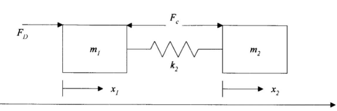
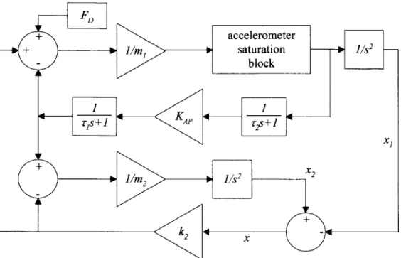
The trajectory planning and the closed loop system use a convenient model given by the Bernoulli’s historical cable equation, completed with a damping factor, that linearly depends

We use this information in a motion planning based control strategy by, successively, turning the driver’s torque demand into a trajectory generation problem for the air mass

The neurological tremor frequency and bandwidth cues have been obtained via a weighted instantaneous average of the mode frequencies and/or summarized via a weighted

Or l’enseignement supérieur au Maghreb, caractérisé entre autres par une massification sans précédent notamment à l’Université, est en mutation depuis

As previously detailed, these amination protocols both provide products in excellent regioselectivity; aryl-substituted internal alkynes (and alkenes) proceed through a

On peut également observer des différences de propriété pour un tissu donné, notamment la substance grise du cortex, dont la porosité varie par exemple selon la

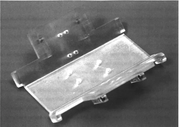
Besides, to be more user-friendly, some of these actuators provide a built-in micro-controller, so the desired position can be set directly as input, this renders the