HAL Id: hal-03039964
https://hal.univ-lorraine.fr/hal-03039964
Submitted on 4 Dec 2020
HAL is a multi-disciplinary open access
archive for the deposit and dissemination of
sci-entific research documents, whether they are
pub-lished or not. The documents may come from
teaching and research institutions in France or
abroad, or from public or private research centers.
L’archive ouverte pluridisciplinaire HAL, est
destinée au dépôt et à la diffusion de documents
scientifiques de niveau recherche, publiés ou non,
émanant des établissements d’enseignement et de
recherche français ou étrangers, des laboratoires
publics ou privés.
Multi-scale approach for analyzing sub-boundaries
induced during dislocational creep of uranium dioxide
Meriem Ben Saada, Nathalie Gey, Antoine Guitton, Benoit Beausir, Xavière
Iltis, Nabila Maloufi
To cite this version:
Meriem Ben Saada, Nathalie Gey, Antoine Guitton, Benoit Beausir, Xavière Iltis, et al.. Multi-scale
approach for analyzing sub-boundaries induced during dislocational creep of uranium dioxide. SF2M,
2017, Lyon, France. �hal-03039964�
Journées Annuelles SF2M 2017
Multi-scale approach for analyzing sub-boundaries induced during dislocational
creep of uranium dioxide
M. Ben Saada
a,b, N. Gey
a, A. Guitton
a, B. Beausir
a, X. Iltis
b, N. Maloufi
a aLaboratoire d’Etude des Microstructures et de Mécanique des Matériaux (LEM3), UMR CNRS 7239,
Université de Lorraine, 54045 Metz Cedex 1, France
b
CEA, DEN, DEC, Cadarache, 13108 Saint-Paul-Lez-Durance, France
Abstract
This study presents an original multiscale approach to characterize and quantify sub-boundaries networks induced in a UO2 sample, mechanically tested in
compression at 1500°C. It consists of taking advantage of three complementary techniques : (1) EBSD (Electron BackScatter Diffraction) to quantify the low and very low angle boundaries with increasing deformation and translate it in Geometrically Necessary Dislocations (2) Accurate-ECCI (Electron Channeling Contrast Imaging) to image and resolve the dislocations arranged in low angle boundaries and finally (3) TEM (Transmission Electron Microscopy) analysis of FIB (Focus Ion Beam) lamellae cut in sub-boundary cross section, previously analyzed by ECCI.
Introduction
Sintered uranium dioxide pellets undergo visco-plastic deformation by creep mechanisms, during power transients in nuclear pressurized water reactors. These mechanisms can be partly reproduced by compression creep tests on non-irradiated pellets. The resulting creep damage in these deformed UO2 pellets is characterized by the production of
dislocations inside the grains, which organize themselves in sub-boundaries, as previously evidenced by means of Transmission Electron Microscopy (TEM) examinations [1]. However, such TEM observations present limitations in terms of representativeness, since they concern only a few thinned grains. In particular, they do not allow obtaining quantified data about the deformation substructure. This study is aimed to fill this lack, thanks to complementary characterizations by EBSD, Accurate-ECCI on bulk samples and TEM on FIB lamellae.
Experimental details
This study was performed on UO2 cylindrical pellets
fabricated by powder metallurgy. They were characterized by a density of 98.1 % of the theoretical density of UO2
and a mean grain size ranging from 13 µm to 20µm (in equivalent circular diameter).
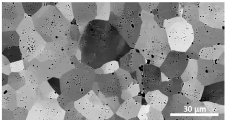
These pellets underwent different uniaxial creep compression tests at 1500°C up to a mean deformation of 16% [2]. After the tests, the pellets were sectioned parallel to the compression axis and the central part of the polished section was examined by SEM. Many sub-grains were evidenced by intra-granular contrast variations in backscattered electrons imaging mode (Figure 1).
Figure 1. SEM micrograph (backscattered electrons mode) of the central part of a pellet after compression test.
Different EBSD maps were acquired in improved angular resolution [3], firstly at a large scale to cover about 300 grains and finally at the grain scale. The data acquisition and post-processing were optimized to obtain a good compromise between acquisition speed and angular/spatial resolution on porous samples [4].
Some sub-boundaries selected on the EBSD map were further analyzed by Accurate-ECCI [5,6]. This technique is not only able to reveal the dislocations induced by creep in the bulk UO2 samples but also analyse their
arrangement, on the basis of a method described in [4]. Finally, TEM thin foils were prepared by FIB milling at chosen locations, previously imaged by Accurate-ECCI.
Results
Large EBSD maps were used to quantify the sub-grain boundaries fractions and GNDs densities, using the ATOM software [7]. This analysis was for example applied to a pellet deformed by creep under 50 MPa up to a mean deformation of 8%. The deduced fraction of sub-boundaries with disorientations lower than 5° increased from 1.3% in the non-deformed sample to 68% (among which 52% were disoriented by less than 1°). The GNDs density was estimated to 7.9 x10¹² m-2 from the EBSD map of the deformed sample. This value was 10 times higher than that measured on an 'as sintered' reference sample. Figure 2 illustrates the analysis at the grain and sub-grain scale. The EBSD map in Fig.2a allows detecting sub-boundaries with disorientations down to 0.1° (white lines). Dislocations and their arrangements in low angle boundaries were revealed by A-ECCI as seen in Fig. 2b. Our experience in ECC-images on UO2 shows that grain
boundary dislocations can be distinguished individually and resolved for sub-boundaries disoriented up to 0.8° (giving a dislocation's spacing of 27 nm for a pure tilt boundary).
Journées Annuelles SF2M 2017
Figure 2. Grain and sub-grain scale analysis of a 8% deformed pellet under a 50 MPa load - (a) EBSP map in improved angular resolution, (b) A-ECCI to highlight the dislocations arrangement in an 0.1° very low angle boundary (purple square in (a))
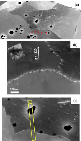
Figure 3 shows the dislocations formed in a grain after a pellet deformation of 16% at a 100 µm/min deformation speed: free dislocations (cf. white arrows in Figure 2a) and dislocations arranged in sub-boundaries (cf. red arrows in Figure 2a and Figure 2b) are clearly observed in A-ECCI mode. TEM thin foils were cut from the yellow boxed area in order to complete the dislocation analysis in a cross section (this last work being underway).
Conclusion
The complementarities of EBSD, A-ECCI and TEM are clearly illustrated in this study. Their consistency is evaluated and leads to new data about UO2 creep
mechanisms presented in [2].
References
1. F. Dherbey, F. Louchet, A. Mocellin, S. Leclercq, Elevated temperature creep of polycristalline uranium dioxide: from microscopic mechanisms to macroscopic behavior, Acta Materiala 50, pp. 1495-1505 (2002). 2. M. Ben Saada, PhD Thesis, Lorraine University, France
to be published in 2017.
3. K. Thomsen, N.H. Schmidt, A.Bewick, K. Larsen and J. Goulden, Improving the Accuracy of Orientation Measurements using EBSD, Oxford Instruments
Application note.
4. M. Ben Saada, N. Gey, B. Beausir, X. Iltis, H. Mansour, N. Maloufi, Sub-boundaries induced by dislocationel creep in uranium dioxide analyzed by advanced diffraction and channeling electron microscopy, Materials
Characterization (submitted).
5. Guyon J., Mansour H., Gey N., Crimp M.A., Chalal S., Maloufi N., Sub-micron resolution selected area electron channeling patterns, Ultramicroscopy 149, pp. 34-44 (2015).
6. H. Mansour, J. Guyon, M.A. Crimp, N. Gey, B. Beausir, N. Maloufi, Accurate electron channeling contrast analysis of a low angle sub-grain boundary, Scripta Mater. 109, pp. 76-79 (2015).
7. B. Beausir, J.J. Fundenberger, Université de Lorraine - Metz, 2015, ATOM - Analysis Tools for Orientation Maps, http://atom-software.eu/.
Figure 3. Accurate-ECCI performed in a grain after a pellet deformation of 16% at 100 µm/min: (a) observation of free and sub-boundary dislocations, (b) sub-boundary marked by red arrows in (a) further imaged in (-220) diffraction condition (d) chosen location for the FIB milling of a TEM thin foil.