Dynamic Node Clustering in Hierarchical Optical
Data Center Network Architectures
by
Georgia Dimaki
B.S. Computer Science, Athens University of Economics and Business
(2018)
Submitted to the Sloan School of Management in partial fulfillment of the requirements for the degree of
Master of Science in Operations Research
at the
MASSACHUSETTS INSTITUTE OF TECHNOLOGY
September 2020
c
○ 2020 Massachusetts Institute of Technology . All rights reserved.
Signature of Author . . . .
Sloan School of Management
August 7, 2020
Certified by . . . .
Eytan Modiano
Professor, Department of Aeronautics and Astronautics
Thesis Supervisor
Accepted by . . . .
Patrick Jaillet
Dugald C. Jackson Professor, Electrical Engineering and Computer
Science
CoDirector, Operations Research Center
Dynamic Node Clustering in Hierarchical Optical Data
Center Network Architectures
by
Georgia Dimaki
Submitted to the Sloan School of Management on August 7, 2020, in partial fulfillment of the
requirements for the degree of Master of Science in Operations Research
Abstract
During the past decade an increasing trend in the Data Center Network’s traffic has been observed. This traffic is characterized mostly by many small bursty flows (mice) that last for less than few milliseconds as well as a few heavier more persistent (elephant) flows between certain number of nodes. As a result many relatively under-utilized network links become momentarily hotspots with increased chance of packet loss. A potential solution could be given by Reconfigurable Optical Data Centers, due to higher traffic aggregation links and topology adaptation capabilities. An example is a novel two level hierarchical WDM-Based scalable Data Center Network architec-ture, RHODA, which is based on the interconnection of high speed equal sized clusters of Racks. We study the traffic based dynamic cluster membership reconfiguration of the Racks. Main goal is to maintain a near optimal network operation with respect to minimization of the inter cluster traffic, while emphasising better link utilization and network scalability. We present four algorithms, two deterministic greedy and two stochastic iterative, and discuss the tradeoffs of their use. Our results draw two main conclusion: 1) Stochastic iterative algorithms are more suitable for dynamic traffic based reconfiguration 2) Fast algorithmic deployments come at a price of reduced optimality.
Thesis Supervisor: Eytan Modiano
Acknowledgments
I would like to thank everything and everyone that made this journey one of the most life changing experiences. First and foremost, my greatest thanks go to my advisor, Professor Eytan Modiano. Thank you for your patience and support, for untangling the thoughts in my brain, for helping me learn how to conduct research.
This material is based upon work supported by the National Science Foundation under Grant No. CNS-1617091. So, thank you NSF as well.
Also I would like to give my thanks to my past advisors, Stavros Toumpis and Vangelis Markakis for being so inspiring and for encouraging me to come to United States. To a mentor and very patient friend, Esmerald. And last but not least, to my first Computer Languages teacher, Makis Kapetis, without whom my career goals would not have been the ones I have today.
Finally, I want to give my warmest thank to my family and friends who always support and trust my decisions. To my grandfather who was the first one to be excited for my trip to Boston and to my grandmother. To my mother, who made sure to check on me, remind me of all important dates and update me with every crazy detail of what is happening around the world. To my father, always curious about my ideas. To my sister who was there in every crisis supporting me with unconditional love. To my uncle, aunt and cousin. To Dimitri, Evangelia, Andriani and Alex who were always there to remind me all my achievements the moments I thought I had none. To Evita and Stephania, who are with me in every spiritual journey I take. To Martin, who shared a wonderful quarantine/thesis writing with me. To my roommates, Basuhi, Martina and Julie, my first and dearest friends in Boston. And to my friends from the OR Center, Kayla, Vassilis, Galit and Sam, for our long discussions with beer and dumplings. Thank you all so much.
Contents
1 Introduction 9
2 Data Center Networks 11
2.1 Inside a Data Center . . . 12
2.2 Hierarchical Data Center Network Architectures . . . 17
2.3 Optical Technology and WDM . . . 20
2.3.1 Optical fibers and light transmission . . . 21
2.3.2 Optical switching . . . 24
2.3.3 Wavelength Division Multiplexing . . . 28
2.4 Optics in Data Centers . . . 30
2.5 Rhoda: A Hierarchical WDM-based Scalable Data Center Network Architecture . . . 36
3 Traffic Based node clustering 41 3.1 Graph Partitioning . . . 43
3.2 On solving the Graph Partitioning . . . 55
3.2.1 Spectral partitioning and geometric based algorithms . . . 58
3.2.2 Move based algorithms . . . 61
3.3 Static Model . . . 69
3.3.1 Problem formulation . . . 70
3.3.2 Methods . . . 75
Spectral Clustering . . . 75
Deterministic methods . . . 88
3.3.3 Network scalability extensions . . . 92
3.4 Time Model . . . 93
4 Simulation and Results 99
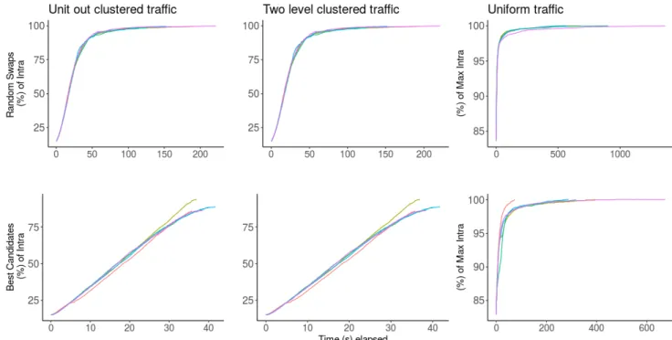
4.1 Traffic patterns used . . . 100
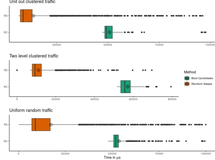
4.2 Iterative methods comparison . . . 101
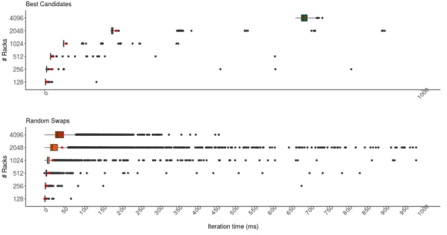
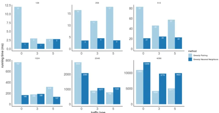
4.3 All methods comparison . . . 105
5 Conclusion 111
A Graph Partitioning Summary 113
B ILP for full RHODA reconfiguration 115
List of Figures 120
List of Terms 121
Chapter 1
Introduction
Data Centers are a big part of today’s Internet, providing service to millions of users around the world. During the past decade an increasing trend has been observed in the Data Center Networks’ traffic. This traffic is characterized mostly by small bursty flows (mice) that last for less than few milliseconds as well as heavier more persistent (elephant) flows between certain number of nodes. As a result of the bursty traffic we have the effect of momentary hotspot links causing congestion and packet losses, even though in general Data Center links are under-utilized.
Optical technology and WDM can help in building adaptable networks with high traffic aggregation within the optical links. Many proposed network architectures have already employed Optical components in order to circuit switch big traffic flows dy-namically [72][34]. More generally, Optical Networks enable better data aggregation and network topology reconfigurability. In this sense we could benefit from hierarchi-cal optihierarchi-cal architectures that lohierarchi-calize the elephant flows in high speed communication clusters, while supporting mice flows as inter cluster traffic in an aggregate manner. The flexibility of such networks to dynamically adapt in the changing traffic patterns has the potential of increasing the link utilization while protecting the network from momentary congestion.
RHODA [87], a novel two level hierarchical Wavelength Division Multiplexing -Based scalable Data Center Network architecture, is based on the interconnection and reconfiguration of high speed equal sized clusters of Racks. The success of RHODA,
or similar hierarchical architectures, highly depends on the reconfiguration of the clusters. In this work we study and evaluate algorithms for the dynamic cluster membership reconfiguration of the network nodes, i.e. network server switches in a data center. Main objective is to maintain a near optimal network operation with respect to minimization of the inter cluster traffic while emphasising on better link utilization and network scalability. We describe four algorithms, two deterministic greedy and two stochastic, and evaluate their performance both in the static and in the dynamic network models. We find that stochastic iterative optimization methods can lead to satisfying solutions and that there is a trade-off between time and optimality. The present thesis is structured as follows. In Chapter2we explore the Data Cen-ter Networks, aiming to find the system requirements they impose on our algorithms. We emphasize specifically on Optical Data Center capabilities closing this chapter with a presentation of the optical architecture of interest, RHODA. Then, in Chap-ter 3we focus on the problem of cluster membership assignment and reconfiguration. This problem belongs to the broader family of problems named Graph Partitioning, so this chapter is dedicated in realizing the complexity of problems of this class as well as the methods used to solve them. We conclude with a presentation of the model and the algorithms we use for the static clustering assignment. Chapter4 continues with the dynamic model for traffic based reconfiguration of the clusters. The results and conclusions drawn from our methods are discussed in Chapter5. Finally, Chapter ?? concludes this work and provides some ideas for future directions in this area.
Chapter 2
Data Center Networks
Data Centers are probably one of the biggest and most important parts of the Internet today [54]. It is an essential component of every company to be successful and serves millions of users around the globe. Their history ages three decades back, in 1991, when e-commerce was an emerging and promising business plan and the client-server model attracted more attention. Companies needed a non-stop online operation and the first goal of data centers was mostly to act as crossover backup with infrastructure to support the increasing needs of users.
Through the years, the requirements and structure for Data Centers matured. Today, a Data Center is defined as a large group of networked computer servers typically used by organizations for remote storage, processing and distribution of large amounts of data. Storage can be a service provided to users, as for example cloud storage, but more generally it is used for all the important user information the company owning the data center holds. Thus the data center needs to maintain and manage a data base. In terms of maintenance and robustness data bases operate in a distributed manner with multiple replicas, thus a big part of traffic within a data center is dedicated to data base fault tolerance and synchronization. Processing as well is performed in a distributed manner for better parallelization (for example in MapReduce framework). Very often it aims to solve computationally intensive large-scale problems, resulting in extensive data exchange within a data center. Finally, closely related to both of the previous tasks, data distribution and exchange happens
either internally to support the data center operations or it aims to update one of the million users that use the data center. Thus, the computational needs and distributed parallel nature of data centers require fast, robust and scalable internal networks.
The aim of this section is to describe those increasing needs in modern data centers that motivate this study. In section 2.1 we present the infrastructure and communication patterns of data centers the last two decades. In section2.2we present the most used network topology of data centers, hierarchical data centers. Section
2.3 introduces the optical technology which enables future optical data centers with various literature examples presented in section2.4. This chapter concludes with the presentation of a novel hierarchical optical data center network architecture in section
2.5, for the operation of which this work is dedicated to.
2.1
Inside a Data Center
A data center is an extended communicative network of servers. Servers manage all the heavy computation that is taking place within the data center. For an effective distributed parallel computing there is need for a supportive network infrastructure that connects the servers and is fast, efficient and robust. Of course so many devices located together generate heat that needs to be managed properly for them to operate at their full potential. So, effectively the key components for a data center are the servers, network switches and communication devices, cables to make the connection happen and cooling system.
All these might seem trivial today, but they took at least a decade to mature into the data centers as we know them. Due to the large number of machines in a data center the complexity and the cost of the network is very high. To be maintainable and manageable a lot of optimization took place, to an extend that may not be immediately realized by a simple observer. The level of detail in a data center’s design starts from the single devices up to even the location of the data center. So as easy as it will be described now, the data center infrastructure is one of the highlights of the networks best design.
Infrastructure
To start, the general structure of a data center is as follows. The data center is broken into clusters placed in different locations. Each cluster comprises of large number of servers and switches that are interconnected through an internal network infrastruc-ture. To keep trouble shooting and cabling complexity at manageable levels, devices need to be organised. Thus placement of machines is very important. Typically 20-40 servers [54] are packed into Racks, a structure similar to a refrigerator with its own cooling mechanism and a central switch to inter connect the servers. The switch is called Top of the Rack Switch (ToR switch). Each ToR switch then connects to the cluster switches that form what we know as Data Center Network (DCN).
The DCN is a uniformly structured network of local devices. To maintain costs reasonable, some of the most common architectures for such a network focus on the use of cheap commercialized switches [2]. This of course requires many more devices and cabling. Cables are placed and packed together in an optimal way, so that their length, which costs in money and latency, is no more than needed, and troubleshoot-ing is possible. The switches’ interconnection infrastructure is the backbone of the communication and computation that takes place in a data center. We seek to pro-vide architectures that are cost and power efficient with high throughput, low latency and fault tolerance. These are of great importance for this study.
Typically however when we discuss or research about data centers we look at a data center cluster in an abstract level. Since servers for example are always connecting to the network through their ToR switch, we can treat them as groups creating the abstraction of a network node which corresponds to one Rack. The network nodes then connect in the way the data center network architecture describes. Switches and other components are also part of the architecture’s specification. In this way we can now focus on the network itself to find the best way to form and analyse it. The machines’ placement and maintenance are not easy tasks but are typically discussed in an abstract level through the complexity metrics of a network.
Applications
So what is the direction of data center networks’ future? This is basically drawn by the way the data center is used. Data centers started growing as simple enterprise networks dedicated to support different services. For this reason they present variation in traffic, caused by the different types of services they provide. However, as their operation started creating value to the owning company, things moved towards more competitive grounds and the initial variation based on the applications run started decaying. Many services became the norm of what a data center should provide and a lot of effort was put to optimize all the internal processing taking place. Nowadays data management methods are almost standardized, taking the lead to data center traffic shaping.
The most common services supported in modern data centers are web mail, web services, user authentication and storage. Others commercial ones include instant messaging, search, video streaming, scientific computing, data analysis etc. Each service to be provided has a major workflow with an effect on the traffic generated, in both the amount of traffic and the way it spreads across the network/computation nodes. What all have in common however is the data manipulation. There are a few very important operations required for the data center to be highly available to the end user and keep the data safe. These include system snapshotting, virtualization, data replication and deduplication - removal of duplicates - and virtual machine migration. Very briefly all these operations verify that the data are backed up and synchronized, when outdated deleted, and that neither the data or jobs processing them are tied on a single machine creating critical points of failure. Thus, there is some traffic shaping depending only to these essential operations, independent of the specific services provided.
Traffic patterns
The knowledge around specific data center traffic patterns however is limited. There are two reasons on why it is so. First, it is difficult to track and analyse the traffic
of many machines in different type of data centers. Thus in the existing literature, common practice it is to track some of the machines, using SNMP (Simple Network Management Protocol) polls [9][10], in strategic locations within the data center and from those to infer the network structure as well as key traffic characteristics [9]. How-ever the picture is not complete, causing conflicting results and conclusions. Second, big vendors do not allow tracking their traffic for various reasons that may extend to personal data safety as well. There have been a few examples though of research originated in a specific company that gives insights. For example in [75] the traffic of Facebook clusters is analysed. The absence of the big picture suggests that for now we can focus on the characteristics the existing research has concluded on, realizing that the results might be outdated as data centers keep expanding.
There are a few traffic characteristics researchers agree on. Generally it seems that there are two types of flows traveling the network. A high percentage of the flows are small in size (≤10KB) and last for a few milliseconds [9]. To these we refer to as mice flows. On the other hand, almost 10% of the flows appear to concentrate most of the bytes transmitted [9] and tend to last longer. These are likewise called elephant flows. Long-lived flows however are not always heavy, as indicated by [75], and load balancing is likely related factor. Not only that but also for many flows internal transmissions appear to be similarly bursty. In terms of interarrival time, flows arrive at microsecond scale and the average number of active flows per rack is less than 10000. What is noticeable is that even though certainly different applications generate different traffic patterns [9][75], according to [9] dominant application traffic patterns are not enough to understand traffic patterns within a data center.
Some other very insightful observations relate to link utilization. It seems that constantly there exist a small number (less than 25% in the core) of hot-spot links the set of whom might remain the same or randomly vary. In general however, both link and buffer utilization seems to follow diurnal patterns [9] [10] [75]. Also, in [32] is observed that in Rack level communication hot-spots tend to be stable in a hundreds of millisecond scale. Interestingly enough, losses do not correlate with high utilization [9]. This suggests that cause are momentary bursts fast enough not to
cause increase in the average link utilization. To accommodate the peaks of traffic load without failures, over-provision of network communication resources is typical in the commonly used data center network architectures [2] [32] [80] with emphasis on fullbisection bandwidth, so that link capacity shortage is avoided. However, this is a worst case scenario approach which leads to even lower network utilization [34], which increases the costs (infrastructure acquiring, maintenance etc.) without necessarily be, as the aforementioned results suggest, more effective than traffic offloading [9] or buffer size tuning [75].
Conflicts in the results of traffic research relate mostly to the traffic Rack locality and packets interarrivals. In [9] it was observed that in big cloud data centers traffic was mostly Rack local. The reasoning behind this observation was related to possibly optimized job placement so that highly communicative components communicate faster without congesting the network. On the contrary this statement fades away under the results of [75]. We could thus say that traffic locality mostly relates to job and virtual machine placement and traffic offloading policies that may vary across different vendors. Regarding packet interarrivals, both [10] and [9] agree on an ON-OFF nature with ON duration characterized by heavy tailed distribution. This is not supported by [75], explained as per destination only phenomenon. Concluding it seems that the points of conflict are caused by algorithmic schemes for traffic engineering applied, which means they should be considered in a per data center manner.
Those traffic characteristics suggest that we should be cautious when it comes to data center deployments. Specifically, as argued in [9] apart from resource over-provisioning, centralized routing or network reconfiguration might also be in per-formance questioning. This is because as networks scale those algorithms need to maintain certain performance guarantees in order to be able to capture the small micro second scale of interarrival times of flows. Otherwise they might impose big delays, and overhead comparable to a typical flow size, making the solutions im-practical. Promising results of [75] however, show that traffic engineering in rack flow aggregation scale has a potential to be effective, since aggregated flows present
more temporal stability, while per application engineering might be valuable as well. Possible approaches include hot-spot fine grained predictions or joint optimization of traffic offloading and routing/reconfiguration.
In another perspective, this elephant/mice flow co-existence could potentially ben-efit by two level hierarchical architectures able to dynamically clusters nodes (Rack) with high communication requirements (elephant flows) together, while satisfy the small communication demand in an aggregate manner. As we shall discuss later in this chapter, such ideas are the drivers of hybrid electrical/optical data center ar-chitecture designs. Since traffic changes through the time, flexible reconfiguration of node cluster membership in a timely manner is critical to get the full benefits from such a design. For highly clustered traffic, or in other words concentrated hot-spot traffic, such an approach would decrease the capacity demands of the network links and provide a better utilization of the network. Given an architecture were this is possible there are a lot of things to consider, such as what are practical reconfiguration algorithms or when should reconfiguration be performed. Subsequent chapters study those exact architectural and algorithmic enablers, their promises and limitations.
Summarizing, all the discussed ideas, special design and uniform characteristic of data center networks create opportunities for optimized network deployment almost analogous to those of supercomputer processors. Data center traffic characteristics are helpful towards these ends. When designing architectural capabilities without focusing on one specific type of Data Center, one should have in mind the different trends in the traffic presents in order to capture a variety of types. The solution proposed can be later tied down to a specific Data Center’s needs, based on services provided or other policy concerns.
2.2
Hierarchical Data Center Network Architectures
Hierarchical design in networks has many advantages when it comes to large networks such as DCN. The inherited modularity and simplicity of such design makes the network easy to maintain, troubleshoot and most importantly scale. For this reason
the most successful and highly used designs follow a tree structure. Even more, complex designs often implement a modular pattern easy to replicate in order to maintain the similar useful principles.
The traditional DCN architectures are hierarchically structured in two or three layers typically, with enterprise equipment at the higher layers. This is called the Multi-tier architecture. In the three tier model the levels are top-down named as core, aggregation and access level. As their name defines, the access level provides connectivity to the end user, the aggregation level aggregates the traffic from the access layer and finally the core acts as the backbone of the network, helping to the traffic distribution.
This type of design often benefits from having downlink with smaller bandwidth
than uplink so that traffic aggregation is achieved. Also, since most of the times not all users access the network simultaneously, ports tend to be oversubscribed, yielding an oversubscription ratio as part of a specific architecture’s implementation specifica-tion. Broadly speaking oversubscription, as the word meaning implies, is when more entities subscribe to a resource than the resource can sustain per unit of time. In a network the oversubscription ratio can have many definitions depending on the point of reference. For example switch oversubscription ratio is the ingress ports (ports of incoming traffic)bandwidthover the overall switchingbandwidth. As for the network oversubscription ratio, [2] defines it as "the ratio of the worst-case achievable aggre-gatebandwidth among the end hosts to the totalbisection bandwidthof a particular communication topology." This translates into a metric of the bottleneck of the in-frastructure when traffic demand is more than the network’s capacity. For effective communication, it is important that balance between effective source utilization and potential network congestion is maintained.
InitiallyDCNwere relatively small (a few hundreds of servers) and this type or de-sign was useful to provide enoughbandwidthfor the end-to-end user communications. As the data center model started becoming more and more adopted at early 2000 the need for more servers and higher communication support was eventually realized. However, enterprise equipment is more expensive and power consuming, while, only
50% of the aggregatebandwidthmay be actually provided [2] (due to oversubscription for example) which makes scaling the network inefficient. Not only that, but also the realization over the increasing computational needs of data centers [70] triggered the collective effort of the research community to create better designs. Some important considerations in the process were also agility, fault tolerance, maximum end-to-end aggregate bandwidth and latency.
Aimed to tackle these scalability issues, the Fat tree [2] architecture proposed in 2008 suggests the replacement of enterprise equipment used in the higher layers of the multi-tier model with commodity switches, typically used in the access layers. The key idea utilized over the network’s topology is called fat-tree and it was originally proposed for hardware efficient supercomputing [57]. Fat tree is a complete binary tree with the special property that the links used in higher tree levels are "more fat". A way for this to be achieved is either with switches that support links of higher capacity in the direction of the core, or by just connecting the higher layers with more than one links. The later can be optimally realized by folding the non-blocking switching network architecture described by Charles Clos in 1953 [23]. For this reason, architectural structures of this form are also referred as CLOS networks. This specific property results into a network with full bisection bandwidth or in other words 1:1 oversubscription ratio. This over-provisioning is unavoidable when it comes to the unpredictable bursty nature of the traffic that we see in the data centers today. The final architecture at [2] is a multi-routed tree, so that the required capacity is achieved with only commodity switches. An important characteristic of this topology is that there are multiple paths between any pair of end-nodes, thus it is more fault-tolerant. Also the maximum number of hops between end-nodes is 2log(n), where log(n) is the tree height, while for k levels connecting N servers we need at least Nxk switch ports and wires [83]. A small topology instance provided in [2] is presented in Figure 2-1
To maintain fast communication, the authors of [2] propose a customized routing that requires specific device addressing and prefix/suffix lookup table techniques. An example of the addressing scheme is also present in Figure2-1. This, along with high cabling complexity, ended up to be a barrier for the adoption of the proposed model as
Figure 2-1: Fat-tree small example as provided in [2]
is, because it requires specific configuration for addressing purposes. However as ar-chitectural alternative became very popular over the following years, triggering other similar and improved architecture proposals [33] [45], as well as real life implementa-tions. Among others, some of the famous examples of architectures employing CLOS structures in their design is the Facebook data center [32] and the Google data cen-ter [81]. Their fast widespread use proved once more the practicality of hierarchical network topologies.
2.3
Optical Technology and WDM
Optical technology has gained a lot of attention the last decade as promising for the upscaling of future data centers [82]. The increased server communication within cur-rent data center along with need for more user support, fault tolerance and network robustness, require bandwidth increase in the network links. Optical technologies, such as transceivers, fibers and switches combined with Wavelength Division Mul-tiplexing (WDM) are able to support higher traffic rates and have low latency and better scalability. Specifically, using WDMand Optical Circuit Switching(OCS) en-ables a rate agnostic network able to adjust to future traffic needs without device change and with less cabling. Finally such networks are more power efficient and thus cost effective.
update are still prohibitive and not all of the optical fabric is characterized by an
economies of scale [34]. For this reason there is slow process in the transition to fully optical architectures. On the bright side, there is room for planning ahead and improving optical technologies before the actual change, which, as the networks start getting to their limits, does not seem to be so far away. In this mindset, many papers have already tried to summarize the requirements for effective data center network optical update.
In [82] the authors, about a decade ago, explored the requirements for a transition to full optical large scale data centers based on existing optical technologies. These requirements include the use ofOCSwith less than 100𝜇sswitching timeand less than 2dBinsertion losses. Similarly in [59] the authors build some requirements around the
multiplexing needed to scale up the bandwidth in optical networks, concluding that denseWDMwill drive the future. Drawing emphasis on theswitching time, critical for algorithm design decisions in data centers, in this section we discuss some of promising optical devices typically employed by modern optical data center architectures along with the benefits of WDM.
2.3.1
Optical fibers and light transmission
When light is directionally projected at an angle through an optical (silica) fiber, it gets reflected and it bounces from the one side of the fiber to the other until it eventually exits the fiber. This light is called a light beam. In this way we can use light as signal carrier and transmit data through optical fibers. This is a simplification of what optical networks are based on.
Optical fibers are an attractive transmission medium since they do not allow for electromagnetic or radio-frequency interference compared to cooper links. Not only that but they also require less maintenance. Optical fibers are made either with plastic or silica glass. There are two types of optical fibers, the single-mode and the mode. Single-mode allows only one wavelength transmission, while multi-mode, due to bigger diameter, allows us to transmit many wavelengths over the same fiber simultaneously. As we will discuss later this enables better capacity provision
opportunities in the optical networks. For this reason their usage extends over the domain of optical networks.
Light communication in a network is enabled through optical transmitters and receivers. In a typical network today there exist both electronic and optical devices. Therefore there is need for the following functionalities: (a) Signal conversion from electrical to optical, (b) Transmission of optical signals, (c) Reception of optical sig-nals and finally (d) Signal conversion from optical to electrical. In networks that employWDMthere exist also the need for (e) wavelength tuning / conversion of the wavelength of a signal, which can happen either at the end nodes so that they are able to transmit in different wavelengths or in intermediate nodes in order to change the
wavelength of an incoming signal before it enters a new fiber. These WDM related operations generally dictate how signals are switched or multiplexed in optical fibers and we shall see how they operate in following sections. Details on how all the above are achieved in the physical layer are beyond the scope of this study. However, to realize the optical alternatives when building or analysing optical communications we would like to know their general performance and costs.
Optical transmitters are the first component of our interest. Their basic operation is the transmission of light signals. The signal can be transmitted in one specific wavelength, in which case the transmitter is fixed, or can change the wavelength of transmission through time, in which case the transmitter is called tunable. Finally, transmitters at the end nodes are also responsible for electrical to optical conversion. The quality and commercialization of a transmitter is based on the way it achieves the aforementioned operations. Able to transmit light in optical communications are both Light-Emitting Diode (LED) as well as laser diode. In large scale optical networks though, laser takes the lead because, due to directionality of light and narrow spectral width, they tend to achieve higher bit rates. In current data centers the most used laser version is the Vertical Cavity Surface Emitting Laser (VCSEL) that has properties such as speed, power and better multi-mode fiber coupling. To be fitted to high bit rates for long distances, VCSEL keeps sending a continuous light that is being amplified and immediately modulated by a semiconductor device called
electro-absorption modulator (EAM) or by Mach-Zehnder Interferometer (MZI). A control module commercialized for this purpose, MZ-SOA, combinesMZIwithSemiconductor Optical Amplifier (SOA) and is of research interest by itself [71][24].
In the tunable transmitters the tuning happens with a similar MZ-SOA technol-ogy. Transmission rates can be up to 160Gbps and tuning time nanosecond and down to sub-nanosecond scale [84]. Important characteristic with key role in WDM is the range of wavelengths a transceiver is able to tune to. ForCoarse WDM(CWDM) we haveCWDMtunable lasers, which have better temperature control however they are more expensive due to low demand [34]. For Dense WDM (DWDM) we have simi-larlyDWDM tunable lasers which tends to have slower tuning time though for "fine grained" tuning. All those choices are to be considered since they have potentially different tradeoffs between bandwidth enabled and tuning times.
Finally, the common electro-optical converter/transmitter is fabricated on a plug and play interface called Small Form-Factor Pluggable (SFP). SFP are available in a variety of transmitter specifications allowing different uses and transmission rates. Most famous one for data centers is the SFP+ achieving 10Gbps transmission rate. The fabrication of SFP has the receiver included, which is our next point of interest. Communication is not complete if the optical signal is not received with an opti-cal receiver. An optiopti-cal receiver, analogously, receives thelight beam and converts it into electrical signal. These devices are basically photodetectors and are much sim-pler. The light is converted into electricity using the photoelectric effect. When the receivers are combined with the transmitters on a device, like in SFP, the combina-tion is called a transceiver. Photodetectors are made out of gallium arsenide whose processing is more expensive and hard to which is unfortunately more expensive to process and cannot benefit fromeconomies of scale [34], thus the same is true for the optical transceiversas well.
There are other key components in the optical communications, not as critical implementation choices though in terms of cost or power consumption. For example many times the signal needs to be amplified, either before it gets modulated or when it needs to travel higher distances. This is what the optical amplifiers take care of.
Another one, which we will also refer to later, is theReconfigurable Optical Add-Drop Multiplexer (ROADM), which is able to add and drop incoming wavelengths before the multiplexing on an optical fiber. Finally, optical circulator is the device that enables bidirectional communication on optical fibers.
2.3.2
Optical switching
Optical switching is the switching of light beams by optical means and can be per-formed in packet level, circuit level or mix of both, called burst switching. Typically,
Electronic Packet Switching (EPS) has been a paradigm of fast communication in large scale networks, while use of circuits has been critical for time sensitive applica-tions. When we move to the optical domain, Optical Packet Switching(OPS) can be either all optical or partly electronic with use of optical-electronic conversion. When conversion is used, as in the electronic domain, processing in all intermediate nodes is required, in which case we care about the number of hops in routing. A key difference with EPSis the lack of buffers and the different processing. Label processing instead of the typical header processing has been more useful in this case [13]. Compared to
EPS, OPS has not been that successful in (optical) networks design. Optical circuit switching on the other hand requires the establishment of alight pathbetween source end destination with wavelength (which acts as the communication channel) routing. Finally Optical Burst Switching (OBS) [89] is a faster alternative of Optical Circuit Switching. Specifically, packets get statistically multiplexed into bursts and , instead of establishing a connection between source and destination before transmission, the destination just gets informed of the incoming burst and the burst gets transmitted. No connection established acknowledgement is needed.
Typically, data center networks have a uniform design and management. Since they belong to one legal entity, devices are located in the same facility and the com-munication protocols used are unified. Thus, all critical network decisions can be planned and optimized under the specific architectural and usage paradigm the net-work implements. In this setting it is obvious that uncertainty of traffic or algorithms in use can be eliminated as much as possible. Thus, circuit or burst switching fits
more to this type of networks, that can then effectively experience the benefits of higher throughput and less packet processing. This is important for optical networks that seek to operate in their full potential communication rates. OCS is actually described as data rate agnostic, referring to the fact that we can transmit at the peak rate of the electronic devices and transceivers used (since no other processing is needed in intermediate nodes as in the packet transmission), which means that to increase the capacity we just only need to improve those electronic bottlenecks without changing the way the network operates. This is extremely important for any future up-scaling process. Historically, OCS has been used in some of the most well known hybrid data center network architectures [34][83][72] to deliver the large data flows over a few Optical Circuit Switches.
Optical circuit switching in optical networks can be performed with use of Op-tical Circuit Switch (OCS) and Wavelength Selective Switch (WSS) that employ
Micro-Electro-Mechanical Systems (MEMS), or with use of passive Arrayed Waveg-uide Grating Router(AWGR). What is especially interesting about these components is that they do not need extra transceivers to operate like electronic switches. This means that the high cost optical transceivers are only needed at the ToR switch, and given that we can add transceivers on demand without changing the other optical elements in a network, the cost is manageable. The different alternatives though of optical switches have their own strengths and weaknesses that need to be considered before network provision.
Optical Switching methods
MEMSuse arrays of reflective surfaces (mirrors) to redirectlight beamsfrom the input ports to the output ports. There are two types of MEMS technologies, 2D digital or 3D mechanical/analog. The 2 dimensional one is basically a cross bar switch of #𝑝𝑜𝑟𝑡𝑠2 mirrors, where initially flat mirrors get activated by being placed in 45 angle.
Because of the two realized states per mirror, 2DMEMSare also called digital. When no mirror is activated on a port, then the light passes through, a functionality used for adding/dropping wavelengths. Depending on the number of ports and the material
used for the mirror switches, it can have switching times up to 10 ms [25] and as low as 10s of 𝜇s [40]. This technology, even though experiencing fast switching times, suffers from light path losses, which effectively means that the more the ports the higher the losses. To provide a perspective, a 16x16 switch has total insertion losses (including the path losses) over 3dB, which is over 1dB increased compared to a 8x8 switch. This makes higher port counts impractical.
To overcome losses and provide a higher port count solution, the second generation ofMEMShad a 3 dimensional design. In 3DMEMSthere are two mirror arrays facing each other with #𝑝𝑜𝑟𝑡𝑠 mirrors each (total 2#𝑝𝑜𝑟𝑡𝑠 mirrors). Light from an input port is directed on a mirror on the first array, reflected on a mirror on the second array until finally is reflected from there to the output port. With continuously adjustable angle mirrors - analog model - and precise alignment the path from input to output becomes way smaller, allowing for higher port counts (> 1000) while maintaining the insertion losses as low as 3dB [25][51]. However, due to precise analog control that they require for the reconfiguration, they typically have slower switching times, at the scale of 10s of ms. For faster switching the mirrors would have to be smaller but then the losses are increased.
Both of those methods are based on light reflection on the mirrors. A dual idea is to use light diffraction instead, changing the amplitude, polarization or the phase of the signal. In this scenario several small elements could be used to diffract the light. A way to use MEMS for light phase change is described in [11] and is promising as a high port microsecond switching element. Other implementations include also
Liquid Crystals on Silicon (LCoS), with which we can modulate phase, amplitude and polarization of incident light beam using many pixels per channel. The pixels are coated with aluminum on the silicon backplane and are reflective.A central unit is controlling the voltage on the pixels can adjust their solid state. The switching time, which highly depends on this adjustment, is relatively slow (up to 100ms). A new material, polymer stabilized blue phase liquid crystal (PSBPLC), is more promising for phase modulation, having a sub-millisecond switching latency. Finally, grating and
nanosecond reconfiguration [74]. Wavelength Selective Switching
Wavelength Selective Switch (WSS), which can be implemented with any of the switching methods described, is a 1xN switch that splits the wavelengths in its input into any N subsets and transmits them to N outputs. Any "leftover" wavelengths are just dropped of the switch. This makes the device suitable for ROADM as well, called also in this case eROADM.WSScan be built with either 3D or 2DMEMS, with the later providing switch speeding orders of magnitude smaller than the former [72]. There also exist commercialized implementations of WSSbased on LCoS [8] or SOA
[74]. These devices are particularly useful in architectures where a Rack connects to N other Racks, since they allow adjusting the link capacity to each of the N neighbors on demand.
Arrayed Waveguide Grating
Another type of optical technology,Arrayed Waveguide Grating(AWG) achieves con-tention resolution in thewavelengthdomain. Each input receives the combined signal of k wavelengths, which is then transmitted to k different length waveguides (fibers). Due to this difference in length the input signals are phase-shifted enough by each waveguide so that each signal is constructively recombined only at one of the output ports. AWGs can be constructed with different materials, among which are silicon (𝑆𝑖) and silica (𝑆𝑖𝑂)2 [56], whose use is more standardized thus the commercialization
of such is easier and so is economies of scale [34].
AWGs can be used in the forward direction as demultiplexers, in the opposite dirrection as multiplexers and have been a useful component for the creation of tun-able transmitters and receivers, and most importantly for our discussion, optical cir-cuit switches called Arrayed Waveguide Grating Router (AWGR). An MxM AWGR
is constructed with M AWGs, allowing the use of M different wavelengths for data transmission. The routing of wavelengths is performed in cyclic manner which allows multiple inputs to reach simultaneously the same output by using different
wave-lengths. In this way AWGRs can realize a complete topology graph. These routers are described as passive devices with zero power consumption that provide loss-less optical connectivity. The scalability of AWGRs is small due to limited number of ports they can support, so to scale up a network, combination of many AWGRs is required. However, to operate, they need to be combined with optical transceivers, who are expensive and power consuming. Thus when extensively used in network architecture design, there are trade-offs between the benefits of their passive nature compared to the increased need for transceivers and wavelength planning. Currently in the market there are 32x32 AWGRs already available [30], while more complex 128x128, 256x256 [90], 270x270 [78] and 512x512 [21] demonstrations also exist in literature .
2.3.3
Wavelength Division Multiplexing
Multiplexing in communication networks refers to the combination of signals into one to be transmitted over a shared medium. Typical ways of multiplexing signals is through time, frequency or code division. In the optical domain the information carrier is infrared light as an electromagnetic wave, while optical fibers are the trans-mission medium. Wavelength Division Multiplexing (WDM) is the multiplexing of optical carrier signals (light) of different wavelength over the same optical fiber. This technique can be realized as the optical alternative of frequency division multiplexing. Optical fibers have two low-loss wavebands of widths 100 nm and 150 nm re-spectively [64]. The granularity in which we are able to distinguish between different wavelengths in this spectrum defines how many wavelengths can be multiplexed within a single fiber. This technically depends on how stable optical tunable transceivers are. If for example a transceiver varies the wavelength it is supposed to tune to by 0.5nm, then 1nm wavelength spacing is needed to distinguish between the different wavelengths. Tunable transceiver components discussed in 2.3.1 are able to realize over 128 wavelengths. The more the channels available the higher bandwidth avail-able per fiber. Depending on the number of multiplexed wavelengthsWDMis referred as Coarse WDM (CWDM) or Dense WDM (DWDM) with the naming convention
inherited to the transceiver categorization. Finally the capacity that a wavelength channel provides depends on the peak electronic processing speed and transceiver transmission rates achievable.
This last remark indicates that we might not be able in the near future to increase those channel capacities. However, through multiple channels multiplexing using WDM we can aggregating many flows together. Intuitively this means that we might not increase capacity per channel but we can significantly increase the number of supported connections. Thus, with demonstrations of 40Gpbs [66] optical transceivers or even 100Gbps achievable data rates over a single wavelength [22], networks that leverage WDM can comprise of millions of servers and support a scale over terabits per secondbandwidth(for example with a 128 wavelengths and 40Gps per wavelength can support over 5Tbps)
The great benefit of WDMis closely related to the optical transmission character-istics and really depends on the enabling optical components. For exampleWDMcan be used to set up any virtual topology over connected physical topologies if properly combined with transceiversand ROADMs [63]. Specifically, given the traffic pattern we can create an optimal virtual network which is going to stay fixed until we tune the transceivers to create a different virtual topology. This can be very useful traffic control mechanism for routing purposes if for instance we want to implement load balancing [67]. The applications thus are far more than just traffic multiplexing. Also,WDMis more practical compared code and time divisionmultiplexing, since to synchronization is required [64].
When it comes to routing inWDMnetworks we have two alternatives, single-hop and multi-hop [65]. In single-hop configurations we require that the communicating nodes are connected through the same wavelengths. This means that when a node a wants to transmit to a node b, the transmitter of a and the receiver of b need to be tuned to the same wavelength. For this setting to successfully support the network’s traffic a lot of coordination is required between the nodes and the transceivers used must be able to tune fast. However the transmission between a pair of nodes avoids any intermediate processing and it stays fast even if the traffic travels a big path on
the physical topology.
On the other hand, multi-hop is the hop by hop stitching of an optical communica-tion path. Therefore as long as neighbor nodes are tuned to the same wavelength, the wavelengths along the path need not to be the same and the routing is executed hop by hop. In this case, optical links can stay fixed for a period of time so no fast tuning is needed. Instead, we need to have fast per hop processing to enjoy a high-speed network and prefer to build minimum average hop length (similarly minimum max flow) topologies. When traffic is relatively uniform, structured topologies that form a regular graph have been successful in meeting both of these goals since they can have controlled average path length and simplify routing. When the traffic is skewed and arbitrary, the regular graph solutions might be susceptible of congestion, thus offloading solutions or topology optimization and reconfiguration might be needed. In all cases, buffering at the intermediate nodes is not so attractive since it requires optical-electronic-optical conversion and is going to slow down the optical network’s speed.
Summing up, if we wish to design fast, high aggregation networks that are power and cost-efficient in the long run, optical networks are an inevitable choice. Especially
WDMenables most of the benefits we can get from optical networks, as for example higher data rates due to traffic aggregation. When passive devices are combined with reconfigurable switches and tunable transceivers that enable WDMthen indeed networks are able to operate in their full potential. However, optical devices can present many trade-offs that we need to acknowledge when designing a new optical network architecture. Our discussion continues with a study of Optical Network architectures to unravel such critical design choices.
2.4
Optics in Data Centers
In the previous section we briefly discussed about the increasing need for optical components inDCNs. This has been understood already the past decades resulting in many proposals about this transition. To fully transition into an opticalDCNthough,
huge percentage of the infrastructure already existing would need to be replaced. Of course this is not backward compatible neither economically feasible yet, due to high costs of optical devices compared to their electronic alternatives. For this reason emerging architectural designs that consider optical devices are either full optical or hybrid in an effort to balance trade-offs.
Hybrid Architectures
Hybrid architectures aim to combine benefits of both the well established electronic packet switching and optical circuit switching alternatives. First of all, typically they require less optical components, making a transition easier due to less network changes and smaller costs. Technically speaking, with addition of few transceivers and few Optical Circuit Switches we can increase the bisection bandwidth of the network without altering the electronic parts and incurring only small increase in cost compared to better electronic alternatives, as for example better Ethernet cables [83]. What is more, this approach allows the coexistence of bothEPSandOCS, something attractive in the networks history as the ATM protocol proves [68]. Data centers, that most of the time tend to be underutilized [9], using a hybrid architecture, can achieve good network performance without network over-provisioning for fullbisection bandwidth, which would inherit higher complexity and costs [34]. It has also been noticed that full bisection bandwidth is less needed at packet granularity [83].
Trying to make the most of it, the proposed architectures often focus on two as-pects, the network traffic demands calculation and the choice of the right flows to circuit switch. As a general observation, since optical switching is slower than elec-tronic switching it mostly fits to large long-lived (elephant) flows [83].Two examples of hybrid architecture are Helios [34] and c-Through [83].
Helios, is based on the idea that it is better to circuit switch only bigger flows while keep packet switching the small bursty traffic. The goal is to achieve similar performance with a full bisection bandwidth network but with less cost (proved 3 times less), complexity (proved 6 times less based on cabling) and power consumption (proved 9 times less). For this to be achieved optical circuit switches based onMEMS
are used along with topology reconfiguration. The full pipeline of Helios contains the flow estimation and optimal circuits calculation, that can take over 100 ms, and finally the network reconfiguration which is again around 100ms. These time results, which tend to be increased with the network scaling, show that indeed the algorithms and the switching time in reconfigurable designs can generate several trade-offs in the network performance.
The spirit of c-Through is not very far from that of Helios. Basic differences between the two is the flow size calculation and the traffic dispatch. Helios’ flow calculation algorithm is adopted from [3] and uses the flow counters immediately available at the switches. This algorithm as well as the optimal circuits algorithm run on a network server. On the other hand c-Through moves all the complexity of demand estimation and traffic demultiplexing to the end nodes. In this way there is no need for customization of the switching components (to retrieve counters and com-municate with a server for example, as Helios would require). For the flow estimation the data are queued an a TCP socket buffer. This allows both the byte calculation as well as head of the line blocking avoidance. Suggested alternatives also contain the explicit statement of demand requirements from the applications.
The authors of the two papers disagree on whether or not end hosts should be part of the network control. Specifically the authors of Helios find the host buffering increasing latency, while the authors of c-Through believe it is essential for better system scaling. The later is also supported by Helios results on scaling, which state that as the network grows the time it takes to access all the flow counts for flow calculation estimation increases as well. Both sides though believe that the circuit switching matches more to large time-insensitive long-lasting traffic and that hybrid architectures can improve the network with small additional cost.
Optical only Architectures
Designing networks from scratch, typically creates opportunity for optimization of every aspect of the new design. When conversions of signal within a network can be avoided we can have both decrease in latency and in power consumption. In this
perspective a network operating completely in the optical domain is preferred. Contrary to the hybrid architectures, the construction of a full optical architecture can be also combined with a new different perspective about data centers. Mainly, optical components can be so fast that we can treat the full architecture as a big, scalable and fast switch, a process mentioned also as network flattening [84][85]. For example Petabit [84] views an optical CLOS constructed from AWGR switches as a huge input-queued switch, due to flow transmissions that do not require any inter rack buffering of packets. Some of the promising features of this design is the reduced latency, power consumption and cabling complexity. Notice that passive optical devices are very attractive choice for fast cost-effective solutions. Another showcase, [85] presents a switch comprised by a unique AWGR. Approaches that treat the network as a switch generally tend to describe in detail all the routing and forwarding algorithms, while they care about fabrication of architecture parts on a single unit/component. This is a promising view of the optical networks however misses a lot of flexibility due to lack of abstraction.
This perspective started being revised few years later. Several proposals started realizing that optical networks have a more flexible and adjustable nature. First of all, components like WSSand OCS help us build architectures that can dynamically alter the physical topology of the network. Not only that, but also WDM allows flexible dynamic capacity provisioning. In other words we can change the link capacity dynamically or structure a new virtual topology over the physical one. This is how network reconfiguration ideas got born.
Once this opportunity was realized, many research groups got dedicated to de-sign reconfigurable architectures and evaluate all the different alternatives. The first idea of both topology and capacity reconfiguration was presented in [18], which we will discuss more later. Briefly though, it is a fully reconfigurable architecture where
MEMS takes the place of a central switch. The first big debate in the literature was whether and to what extend MEMSwere actually useful, since their per port cost is relatively high. Other components, like AWGRs for example, seem to be way more efficient in terms of power consumption and cost. First paper to oppose the idea
of optical switches was Wavecube [19]. Using exactly the aforementioned reasoning, [19] suggests interconnection of ToR switchs immediately and without intermediate switch layers, in order to form flat, n-dimensional cube network graph. Only WSS
are used for link capacity allocation flexibility, which makes the architecture dynam-ically reconfigurable, at least partly. Similarly following a flat architecture design, OPSquare [88] usesAWGRs to interconnect the ToR switchs instead and it does not support capacity allocation flexibility. However, the number of interconnected ToR switchsscales as the square of the optical packet switches port count (OPSquare) and the latency is less than 2𝜇𝑠.
Even though described as flat, the structure of OPSqure entails a two level hier-archy and cluster construction that make it more flexible when it comes to routing. Actually, the hierarchical design can realize better scalability. The architecture called PODCA [86] is another successful example of hierarchical networks based onAWGRs. According to the authors it is able to support 2 million servers with latency as low as 9𝜇s and 100%throughput, which is impressive. A drawback however is that the topology is static as well as the link capacity, which meas that it should better be combined with load balancing techniques. An interesting part for one to notice is that even though AWGRs are passive, for an effective optical network we will need increasingly many transceivers as also [84] suggests. This means that the costs are not as low as we would wish.
Soon it became clear that in order to enjoy faster networks a combination of those approaches need to be done. Specifically, as hybrid models suggest, we can definitely benefit by dynamically "following" the traffic. At the same time topology reconfiguration and capacity adaptation enable these network dynamics. Finally, for scalability and lower latency purposes, the use of some hierarchy in the designed architecture becomes important. We seek to study a combination of all those ideas. First we will describe a flat architecture of similar goals. In the next section, the architecture of interest is described.
Reconfigurable (all) Optical Architecture
One of the first fully reconfigurable attempts in this area is OSA [18], an optical switching architecture. OSA, depicted in Figure 2-2, leverages OCS and WDM to dynamically adjust the network topology to traffic demands. Connecting each ToR switch in k ports of a MEMS switch is able to realize all k-regular graph topologies between the ToR switchs, with key optical component a WSS per ToR switch that through WDM enables capacity variation of the network links. Through the flexibil-ity of the optical paths capacflexibil-ity it is able to adjust better to skewed traffic patterns or hot-spot traffic with relative to k number of hot-spots, without the need of over-provisioning. Main difference with hybrid or other all optical solutions is that it still packet switches the traffic instead of transmitting flows. Finally it is shown that this fully reconfigurable alternative has higher bisection bandwidth compared to hybrid alternatives.
Figure 2-2: The OSA as presented in [18]
There are two limitations in this design. The first one is the scalability of the model. In the design the basic topology configuration is done by a central MEMS
switch. This means that the size of the network is limited by the maximum number of available ports on the switch. Notice that as a network grows not only a higher port count is required but also the realizable k-regular graphs need to be of higher degree k for the model to operate optimally, which means that the network size might
not be able to linearly grow with the port count of the switch. The second one is the switching time. We already have discussed that MEMS take a considerable time to reconfigure compared to the mice flows lifetime. In the suggested implementation the running time is 10s of milliseconds scale, while the running time of the recon-figuration algorithms alone is almost 300ms. The reconrecon-figuration seems to mostly affect mice flows and addressing the issue, the authors discuss potential solutions like immediate ToR switch to ToR switch connectivity for mice flow transmissions or a fixed preexisting path that does not change. These alternatives however are closer to the idea of the hybrid architectures. Notice that in the hybrid case the electronic part is still functional during reconfiguration, which means that no traffic disruption is needed. Since goal of this work is to prove the potential of the full reconfigurable designs, both the scaling and faster algorithmic alternatives for the reconfiguration of the network are left for future research.
Even though research has already taken the action towards creation of more flexi-ble, traffic aware, adjustable networks, not many past works have realized the extend to which reconfigurability is leading or not the future path of data centers. OSA is the preamble of an architecture with central role to this work. RHODA, a Reconfigurable Hierarchical Optical Data center Architecture, with the ability to alter the network clusters (PoDs), is described in the next section (2.5).
2.5
Rhoda: A Hierarchical WDM-based Scalable Data
Center Network Architecture
A very novel all optical hierarchical architecture was proposed last year [87]. It is an optical architecture that, as many, realizes the benefits of a hierarchical tree type structures that have been employed successfully by big data centers for years, while offering a new optical dynamically adjustable alternative. Aggregation has been found both reasonable and valuable for bursty traffic, especially in optical data centers where switching times are higher [34]. Thus, we can benefit by forming clusters of Racks
in two ways: big flows are transmitted in low latency high capacity clusters while the small bursty traffic is gets aggregated and then transmitted in the inter-cluster network. Of course, for such an architecture to be effective we need a way to place high communication nodes in the same or close by clusters. One way to achieve this is through job scheduling or virtual machine migration. What RHODA proposes instead is a reconfigurable design able to dynamically adjust to any type of changing traffic. The structure of RHODA is summarized in Figure 2-3
Figure 2-3: RHODA as found in [87]
RHODA has two levels. In the first level Racks form clusters of size k each. The second level is responsible for the clusters’ interconnection. The design of those two levels consist of five parts, the intra cluster network, that describes the connectivity of the nodes within a cluster, the inter cluster network, that describes the clusters’ connectivity, the cluster membership network that manages the cluster membership of the Racks and finally two parts for demultiplexing and multiplexing the optical signals to be transmitted. All parts are carefully designed so that the architecture can be easily extended and scalable. Main components are AWGRsto form the high communication clusters,MEMSto offer topology reconfiguration and finallyWSSfor flexible link capacity. We shall then describe the parts in more detail.
Initially, T wavelengths from eachToR switchget aggregated and connected to the cluster membership network (CMN). The CMN consists of Optical MEMS switches
that describe the cluster membership of the ToRs. There is one input for each ToR and the outputs are able to realize a permutation of the inputs. Then each output is fixed to forward the traffic to a specific cluster. To alter the cluster membership we just need to reconfigure the switches and obtain a new permutation of the ToR inputs at the outputs.
The traffic then moves to the demultiplexing stage. There a set of WSS, each dedicated to the traffic coming from a specific CMN output. The WSS splits the incoming wavelenghts in two sets, the inter cluster traffic set and the intra cluster traffic set. The two sets get then forwarded to their respective part.
Each cluster network receives exactly k of the aforementioned intra cluster traffic sets. AnAWGR is responsible for supporting the intra cluster connectivity, typically able to realize a complete graph of the connected nodes. We can assume for now that this is the case.
The traffic that gets forwarded to the inter cluster network gets connected to the first substage, a grooming switch, which basically restructures the transmitted flows so that proper aggregation is performed. There are three more substages. Briefly, the first part performs capacity allocation to the inter cluster links, while the second is responsible for setting up a d-regular inter cluster network topology. The third is the aggregation substage that collects and aggregates all the traffic for a specific cluster. Finally the flows need to be sent to their destinations. This is achieved in the following way. First the traffic for each cluster is decomposed to traffic for each rack. Then those flows get combined in the multiplexing stage with the respective flows from the AWGR output. The aggregated flows then moves to the circulators that make sure to deliver the traffic back, through the cluster membership network , to the respective Rack.
Intuitively, the inter cluster network is nothing else but a scalable OSA design. Generally there are many details regarding the scaling factor of the system that depend both to the number of switches used as well as the number of trasceivers. These details are omitted here but can be found in [87].
cluster membership assignment and routing and wavelength assignment optimization (an ILP for further insights is provided in Appendix B). However this is NP-hard problem, thus we decompose the problem and seek suboptimal solutions. Specifically, instead of solving the joint problem we can start by defining an optimal based on the traffic clustering of the racks, then generate an optimal intra cluster routing solution and finally solve the inter cluster routing problem on the aggregated clusters’ traffic. In this work we care about the first part: How can we form an optimal Rack clustering, and even more, how can we dynamically change it in an optimal way so that it follows the fast changing traffic patterns? When reconfiguration should be performed and what are the limitations of dynamic clustering? The next chapters investigate this problem in detail.
Chapter 3
Traffic Based node clustering
An important part of the RHODA Architecture that makes it particularly attractive is its ability to alter the clustering of Racks. This enables traffic based dynamic recon-figuration which would allow traffic localization contrasting methods such as dynamic job scheduling, virtual machine placement etc. Compared to other approaches that dynamically schedule flows and naturally realize pairs of communicating nodes,as for example [72], RHODA takes a step further to be able to dynamically realize groups of communicating nodes, giving a more stable over time alternative for distributed job efficient execution. We seek to model and study the cluster reconfiguration possibility of this architecture, which would potentially provide us with an architecture fully self adjustable to traffic demands. Treating server Racks as the smallest building block before traffic enters the optical domain, we create the network node abstraction, which represents a Rack of around 40 servers. We define the traffic based node clustering for the RHODA architecture as follows:
Definition 1 (Traffic based node clustering) Consider a set of network nodes 𝑉 of size 𝑁 and an 𝑁 × 𝑁 traffic matrix 𝐷, where 𝑑𝑢𝑣 is the rate of the traffic flowing
from node 𝑢 to node 𝑣, with 𝑢, 𝑣 ∈ 𝑉 . Find a clustering of the nodes in sets of fixed size 𝑟, such that the aggregated traffic rate exchanged between clusters - inter cluster traffic - is minimized.
![Figure 2-1: Fat-tree small example as provided in [2]](https://thumb-eu.123doks.com/thumbv2/123doknet/14754260.581725/20.918.166.758.108.352/figure-fat-tree-small-example-provided.webp)
![Figure 2-2: The OSA as presented in [18]](https://thumb-eu.123doks.com/thumbv2/123doknet/14754260.581725/35.918.228.694.548.830/figure-the-osa-as-presented-in.webp)
![Figure 2-3: RHODA as found in [87]](https://thumb-eu.123doks.com/thumbv2/123doknet/14754260.581725/37.918.148.764.358.625/figure-rhoda-as-found-in.webp)