HAL Id: hal-00455624
https://hal.archives-ouvertes.fr/hal-00455624
Submitted on 10 Feb 2010HAL is a multi-disciplinary open access archive for the deposit and dissemination of sci-entific research documents, whether they are pub-lished or not. The documents may come from teaching and research institutions in France or abroad, or from public or private research centers.
L’archive ouverte pluridisciplinaire HAL, est destinée au dépôt et à la diffusion de documents scientifiques de niveau recherche, publiés ou non, émanant des établissements d’enseignement et de recherche français ou étrangers, des laboratoires publics ou privés.
X. Diao, Messaoud Kara, Jian-Jin Li, K.M. Hou, H. Zhou, A. Jacquot
To cite this version:
X. Diao, Messaoud Kara, Jian-Jin Li, K.M. Hou, H. Zhou, et al.. Cooperative inter-vehicle communi-cation protocol with low cost differential GPS. Journal of Networks, Academy Publisher, 2009, 4 (6), p. 445 - p. 457. �hal-00455624�
Cooperative Inter-vehicle Communication
Protocol with Low Cost Differential GPS
Xunxing Diao1, Messaoud Kara1, Jian-jin Li1, Kun-Mean Hou1, Haiying Zhou2, and Aurelien Jacquot3
1 LIMOS Laboratory UMR 6158 CNRS, Blaise Pascal University Clermont-Ferrand II, France 2 School of Computer Science, Harbin Institute of Technology, China
3 CEMAGREF, 24 Avenue des Landais, 63172, Aubière, France
Abstract—This paper describes a cooperative MANET
protocol dedicated to intelligent transport systems, named CIVIC (Communication Inter Véhicule Intelligente et Coopérative). The CIVIC protocol is an auto-configuration inter-vehicle communication protocol, which supports ad-hoc and infrastructure networks, contains reactive and proactive routing components, and adapts different wireless standards. It is a context-aware protocol reacting to vehicle status, road traffic, and geographic environment. It supports location-based communication. To improve the accuracy of GPS, it integrates a localization solution called LCD-GPS (Low Cost Differential GPS). It has been implemented and experimented on the LiveNode sensor developed by our lab. At the end of this paper, an application project MobiPlus is introduced.
Index Terms—ITS, IVC, MANET, WSN, auto-configuration,
infrastructure support, hybrid routing protocol, context-aware, localization, differential GPS
I. INTRODUCTION
Each year in Europe, 1,300,000 vehicle accidents result in 1,700,000 personal injuries. The financial cost of vehicle accidents is evaluated at 160 billion euros (approximately the same cost in the USA [1]). The ITS (Intelligent Transportation System) is considered as the key technology allowing 50% reduction of accident numbers by issuing hazard warnings [2]. In addition to improve road traffic safety, the ITS contributes to optimize the traffic flow, offer a better driving experience, and increase the accessibility of public transports especially for disabled passengers.
An essential component of ITS is the IVC (Inter-Vehicle Communication). It ensures that the data from other ITS components, which includes sensing system and computing system, flows among vehicles and roadside infrastructures efficiently. In high mobility scenarios like IVC, non-cooperative client/server systems are not fully appropriate. A proposed solution is to introduce MANET (Mobile Ad-hoc NETwork) for its characteristic of cooperative communication and non-central distributed control [3][4][5]. The economic impact of this solution is expected to be substantial, but there are still open issues in MANET such as the limitation of QoS, network interference, and incomplete cooperation methods [6]. Until now, the practical MANET protocols and mathematic models are carried out within the scope
of fixed and wired network, so the previous issues remain to be solved.
Moreover, comparing with general-purpose MANET communications, the IVC has its unique features that have not been fully explored [5][7][8]. For example, the topology and density of vehicular network are much more variable, thus there is a requirement for a new routing protocol to minimize the administrative overhead [9]. The distribution of vehicular network is generally along roads. It provides the opportunity for IVC to deploy the roadside infrastructure for supporting network access and QoS, but as well, it raises the expectation for the adaptability to different wireless standards. Besides, the position and direction of network nodes could be obtained by GPS (Global Positioning System) on vehicles.
An accurate positioning system is one of the foundations for any IVC application. It is well known that the GPS is inaccurate in big cities, particularly in EU where the roads are narrow and crossroads are very close. To improve the accuracy of GPS, the DGPS (Differential GPS) [10] has been introduced. However, installing a reference station for DGPS is complex and very expensive (about 30,000 €). To solve this problem, we develop a localization solution called LCD-GPS (Low Cost Differential GPS). This solution improves the accuracy of GPS even in dense urban areas and it can be used for mobile tracking.
Based on the previous factors, this paper presents a new inter-vehicle communication protocol dedicated to ITS, named CIVIC (Communication Inter Véhicule Intelligente et Coopérative). The CIVIC protocol is a cooperative MANET protocol integrated the supports of roadside infrastructure. It has mechanisms to adapt to multiple wireless standards. The communications by CIVIC protocol are auto-configured and location-based. The CIVIC protocol provides the original position to LCD-GPS, and performs more efficiently based on the accurate position generated by LCD-GPS. The new experiments for both CIVIC protocol and LCD-GPS are presented in this paper. In these experiments, we use a specific sensor called LiveNode (LImos Versatile Embedded wireless sensor NODE) [11].
The remainder of the paper is organized as follows. In the next section, an overview of related works will be summarized. Section 3 explains the details of CIVIC protocol. Section 4 is dedicated to the concept and experiments of LCD-GPS. Section 5 presents the
experiments for the CIVIC protocol. Section 6 outlines the MobiPlus project, which consist of an application of CIVIC protocol and the LiveNode sensor. Finally, conclusion and ongoing work are presented.
II. RELATED WORKS
A. Research Projects
The ITS projects concerning IVC have been launched in Europe (FleetNet [12][13], CarTALK2000 [14][15]), Japan (cooperative driving [16]) and USA (VII [17][18]).
The IVC of FleetNet (2000-2003) and CarTALK2000 (2001-2004) are based on UTRA-TDD (UMTS Terrestrial Radio Access Time Division Duplex). The UTRA-TDD is a third generation mobile telephone technology. It has about 1 km radio range, and 384 Kbps to 2 Mbps bandwidth according to the vehicle speed. It operates in the free frequency band from 2.010 GHz to 2.020 GHz [12][14][19][20]. The IVC based on the development of UMTS technology can minimize the cost of access medium, and guaranty the total compatibility with the 3G mobile phone.
In Japan, the cooperative driving project (1993-2000) is started by JSK (Association of Electronic Technology for Automobile Traffic and Driving). It utilizes 5.8 GHz DSRC (Dedicated Short-Range Communication) for transmitting data, and it employs DGPS for measuring vehicle location [16][21]. The DSRC is adapted to the applications of highway infrastructures management such as ETC (Electronic Toll Collection) and vehicle counting, but it may not be appropriate for general IVC applications such as security and Internet access. This project develops a short-range cooperative communication protocol named DOLPHIN (Dedicated Omni-purpose inter-vehicle communication Linkage Protocol for HIghway automatioN) [22].
In USA, the leading project is called VII (Vehicle Infrastructure Integration, 2004-2010). This project is focused on improving safety and roadway management. Its communications involve vehicle-to-infrastructure and vehicle-to-vehicle by using 5.9 GHz DSRC [17][18]. In addition to VII project, there are researches at VTTI (Virginia Tech Transportation Institute, USA) trying to provide communication solution in high mobility scenarios by using the low-cost WLAN (Wireless Local Area Network) technologies such as IEEE802.11b [23].
The previous projects provide cooperative IVC solutions either on the limited application domains, or with the fixed wireless techniques. Their research efforts are more focused on the general-purpose Internet access with lower real-time constraint, mobility and reliability. The CIVIC protocol gives emphasis to adaptability, and it puts more effort to design the robust auto-configured routing mechanisms.
B. MANET Routing Protocol
The MANET routing protocols can be divided into three classes: proactive, reactive, and hybrid.
The proactive routing protocols maintain up-to-date routing paths for partial or entire network. In order to keep correct routing paths, each node needs to generate
sensing messages to explore network periodically. The network traffic therefore increases significantly. The main proactive protocols are OLSR (Optimized Link State Routing) [24], DSDV (Destination-Sequenced Distance-Vector) [25], and TBRPF (Topology Dissemination Based on Reverse-Path Forwarding) [26].
The reactive routing protocols determine a routing path only when a demand is received. The main reactive protocols are DSR (Dynamic Source Routing) [27], AODV (Ad-hoc On Demand Distance Vector) [28], TORA (Temporally-Ordered Routing Algorithm) [29], ABR (Associativity Based Routing) [30], and SSR (Signal Stability Routing) [31].
The hybrid routing protocol combines the advantages of the proactive and reactive protocols. An example is ZRP (Zone Routing Protocol) [32]. It includes two routing components: a proactive intra-zone routing component and a reactive inter-zone routing component.
In general, the reactive protocols are more efficient in terms of bandwidth utilisation and more adapted to networks with rapid changing topology, because their routing path explorations are performed only on demand. However, the proactive protocols are more interactive (the response time is shorter) because the message is sent immediately without performing route request. Hence, the proactive protocols are suitable for static network while the reactive protocols are more adapted to dynamic network.
The previous routing protocols have not considered the particularity of the ITS such as direction, location, road traffic, and road map. In addition, the requirements of MANET in IVC applications such as intelligent urban transportation system or agricultural vehicle system are different from the ones with general-purpose [12][23]. Thus the existing MANET routing protocols are not adapted to IVC.
III. CIVICPROTOCOL
The concepts and features of CIVIC protocol are listed as following:
A. Multiple Wireless Supports on Network Node
To adapt different roadside infrastructures and utilize more radio spectrum, the CIVIC protocol is designed to support multi-radio and multi-channel on network nodes. The radio and channel should be auto-configured to minimize interference.
The LiveNode sensor, to which the CIVIC protocol is implemented, can be equipped with three types of wireless access medium: Wi-Fi (IEEE802.11b), ZigBee (IEEE802.15.4), or GSM (GPRS). Several LiveNode sensors can be connected together to enable the multiple wireless supports by using extension connectors (SPI, I²C, and I/O connectors).
The Wi-Fi and ZigBee have been adopted by the CIVIC protocol. From inter-vehicle communication, smart home, to telemedicine, the Wi-Fi enables many applications to connect to the Internet. With an appropriate antenna, the radio range of Wi-Fi can reach 1 Km with the vehicle speed about 100 Km/h. A new
trend of wireless standard is ZigBee, which requires lower cost and lower power. Its maximum outdoor radio range is up to 1.6 Km.
B. MMRS for Infrastructure
The topology and density of vehicular network change dramatically according to location and time. In some scenarios, for example at night and on bad weather, the density could get very low. Thus, only using mobile ad-hoc connections is not robust enough for IVC. The CIVIC protocol deploys the MMRS (Multi-support, Multi-service Routers and Servers) along the road to improve the network access and QoS.
The main functions of the MMRS are: i. Ensure the network connection to nodes in range; ii. Send the private message to a given node; iii. Send the alarm message to all nodes; iv. Forward message(s) to other MMRS.
The MMRS should be connected with wired networks, otherwise the network connectivity can not be assured. Each MMRS maintains at least two message queues. The first one stores alarm messages, and the second one holds private messages. When a mobile node reaches an MMRS, this node broadcasts a request message including its VID (Vehicle IDentifier). If an alarm and/or private messages exist, the MMRS sends these messages back to the mobile node. The private message for this mobile node will then be deleted from the private message queue. The Fig. 1 shows how a message is forwarded from one node to another by mixed networking of ad-hoc and infrastructure.
C. Context Based Communication
The CIVIC protocol considers the communication contexts in a vehicular network, which are quite different from the ones in general-purpose MANETs. The nodes in a vehicular network are generally distributed along roads with directional movements, but in the MANETs with general purposes, nodes are grouped around an access point with random movements.
A major context of IVC is the distribution. It can be used to estimate the bandwidth utilization and the capacity of a vehicular network. As previously mentioned, when a mobile node passes an MMRS, it sends a request message including its VID. The message may also contain its position, so the MMRS can estimate the distribution of vehicular network, and then a better knowledge concerning real-time traffic state will be obtained.
The direction of nodes is another major context of IVC. By introducing the direction, the PDR (Packet Delivery Ratio) and delay can be improved significantly [33].
Although the Euclidean direction is not appropriate for defining the direction of mobile node when roads are too winding, it may be applied for a short segment of a road. The CIVIC protocol assumes that all mobile nodes have an itinerary, and they move in a known environment. Thus, the direction of a mobile node is updated between two MMRS based on three factors: the itinerary and position of the mobile node, and the road map.
By considering the contexts of distribution and direction, the CIVIC protocol can determine how to transmit messages (ad-hoc or infrastructure, interval of sending messages, etc.). In addition, to obtain the correct position of a node, the LCD-GPS (described in section 4) implemented road maps will be used by mobile nodes and/or MMRS.
D. One-hop Link Stability
A common way to ensure QoS in network routing is to keep stable connections. In a high mobility scenario like vehicular network, the survival time of stable connections has great impact to QoS.
The CIVIC protocol assumes that the connection between one-hop neighbour nodes is stable. The stability of connection is maintained by the neighbour knowledge exploration. The exploration is proactive, it is implemented by the exchange of “Hello” messages, and it must be preformed only when the link stability is out of date. The dynamic interval of neighbour knowledge exploration is evaluated by Δt=Min
{ }
Δtr with equation set (1): otherwise. , ; and if , ; and if , ; if , max max max max max max max max max max max ⎪ ⎪ ⎪ ⎪ ⎩ ⎪ ⎪ ⎪ ⎪ ⎨ ⎧ − − = Δ < < − − + = Δ > > − − + = Δ = ∞ = Δ r s s r r s r s r r s s r r s r s r s r r s r s r r v v x x t v v x x v v x x R t v v x x v v x x R t v v twhere R is the radio range in the worst case; xs is the
location of source node, and vs is its average speed; xrmax
is the location of one of its neighbour nodes, and vrmax is
the speed of this neighbour node. Both xrmax and vrmax are
adjusted by the worst case GPS error. The equation set (1) means that the interval of sending “Hello” messages depends on the distances and the relative speeds between the source node and its neighbour nodes.
After neighbour knowledge explorations, each node stores its neighbour information for the further multi-hop routing algorithm.
E. Multi-hop DANKAB
Due to resource constraints of embedded sensor and negative effects from radio irregularity [34], broadcast may be a suitable transmitting scheme for IVC routing algorithm. However, broadcast in an MANET could cause serious redundancy, contention, and collision [35]. Therefore, it is important to determine a correct broadcasting technique for CIVIC protocol. Williams [36] classifies current broadcasting techniques of MANET to four categories: MMRS MMRS MMRS Area with MMRS (Infrastructure) Area without MMRS (Ad-hoc)
Figure 1. Mixed ad-hoc and infrastructure networks.
1) Simple Flooding (SF): In SF, every node rebroadcasts a packet exactly once until all reachable nodes have received the packet. SF is adapted to low node density and/or high mobility networks.
2) Probability Based Method (PBM): PBM is similar to SF, but every node rebroadcasts a packet with predetermined or counter-based probability. When the probability is 100%, this method is identical with SF.
3) Area Based Method (ABM): Instead of probability, every node decides whether to rebroadcast a packet depending on an estimation of distance or location.
4) Neighbours Knowledge Method (NKM): Every node makes a decision on rebroadcast by its one-hop or two-one-hop neighbour knowledge. The neighbour knowledge is achieved by the periodic “Hello” packets.
Tseng [35] proved that the adaptive counter-based and location-based scheme could resolve the dilemma between reachability and broadcast storm. The interval of sending “Hello” packets is also important to achieve efficient broadcast. Moreover, the radio irregularity may seriously affect directional routing especially when a packet can only be sent to one direction. Zhou [34] proposes using the multi-round discovery technique to solve the problem.
The CIVIC protocol adopts DANKAB (Directional Area Neighbour Adaptive Broadcast) when transmitting message by multi-hop. To use DANKAB, every node stores the location knowledge from neighbour nodes, destination nodes, and next MMRS. In case of one-hop message sending, one-hop broadcast is used. In case of multi-hop message sending, if the location of destination node is unknown by the next MMRS, a request for the location of destination node will be performed by SF to all directions.
When the location of destination node is known, the next hop will be selected according to the locations of neighbour nodes. The Fig. 2 indicates this process. We define the direction area as an angle α with a default value of ±30°. In order to reduce the number of messages in the network, only the nodes within the direction area can broadcast the message. If there is no node within the direction area, the angle α will be gradually increased (e.g. 45°, 90° and 180°) until the next hop is found. An node can be a candidate in the next hop if -tgα≤tgβ≤ tg . α
The tgβis calculated by the trigonometric equation (2):
(
)(
) (
)(
)
(
r s)(
d s) (
r s)(
d s)
s d s r s d s r y y y y x x x x x x y y y y x x tg − − + − − − − − − − = β In equation (2), (xs, ys), (xd, yd) and (xr, yr) are the
locations of source node S, destination node D, and routing node R, respectively.
When there is more than one node in the direction area, two approaches can be adopted for selecting the next candidate node. The first one is energy aware competitive broadcast. The node with more remaining energy will rebroadcast more quickly. Thus, other nodes in the same direction area will discard the redundant message. The second one is to let the source node selecting the node for next hop. It requires the additional information of remaining energy when exchanging “Hello” messages, but it generates less routing data. We use the second approach for the experiments in this paper.
After defining the next hop of source node, the processes of DANKAB repeat hop-by-hop until the message reaches the destination node.
F. Summary
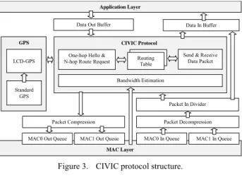
The CIVIC protocol stack is represented by the Fig. 3. In general, The CIVIC protocol has three mechanisms when transmitting data:
The first one is the neighbour knowledge exploration. At intervals, each node gets its one-hop neighbour information by exchanging “Hello” messages. This proactive mechanism will be performed only when neighbour information is out of date.
The second one is routing request. It can be proactive or reactive depending on the application requirements. The source node obtains the position of destination node by MMRS or by SF request. After that, the routing process performs only to the direction on demand by using DANKAB.
The last one is the sending of application data. After the routing path has been obtained, the data from application layer will be transmitted. If the data rate is low, DANKAB can also be integrated to the data sending, and the routing request can be ignored. For our experiments in this paper, the two mechanisms are separated.
Data Out Buffer
Application Layer MAC Layer Data In Buffer Packet In Divider Packet Decompression MAC1 In Queue MAC0 In Queue
MAC0 Out Queue MAC1 Out Queue Packet Compression LCD-GPS GPS Standard GPS Bandwidth Estimation CIVIC Protocol Routing Table One-hop Hello &
N-hop RouteRequest
Send & Receive Data Packet
Figure 3. CIVIC protocol structure.
D S α S: Source node R: Neighbour node of S D: Destination node β R
Figure 2. DANKAB routing concept.
IV. LCD-GPSCONCEPT AND EXPERIMENTS
As previously mentioned, the CIVIC protocol is a location-based IVC protocol, and it requires accurate positions for transmitting data to the right direction. The Standard GPS Service (civil GPS) only provides accuracy around 13 m (95%) in the horizontal plane, and 22 m (95%) in the vertical plane [37]. The measured performance in open areas is usually few meters (1-3 m) [10][38], which is much better than specification [37]. However, it is not the case for the urban scenarios where buildings may decrease accuracy. In urban scenarios, the accuracy of location-based services is estimated to be three meters. For the application like hazard warning, the minimum accuracy is one meter [39].
In this section, a solution called LCD-GPS (Low Cost Differential GPS) is presented. The LCD-GPS provides network nodes with the original positions and the accurate positions. It uses CIVIC protocol to collect original positions from network nodes, and then it maximizes the efficiency of CIVIC protocol by offering more accurate positions including differential GPS corrections.
A. Main Idea
The main idea of the LCD-GPS solution consists of a set of standard GPS integrated with communicating receivers (LiveNode sensor [11] in our experiments). Unlike other Differential GPS solutions, which are very expensive and complicated to be installed, LCD-GPS uses only low cost standard GPS. Some fixed nodes are used as reference stations. The other nodes are mobile nodes. Reference stations and mobile node have the same hardware architecture. We assume all reference stations know their position coordinates with a good accuracy. Reference stations analyze continuously the instantaneous GPS errors and cooperate to deduce a global error correction. This correction is sent by CIVIC protocol, and it has to be applied to get better accuracy for mobile node positions (or fixed nodes which are not part of reference stations) than the standard GPS one.
The LCD-GPS concept has been presented in details in papers [40][41] and [42]. This new contribution presents the state of development in multi-hop scenarios. New experiments and results prove the main ideas in our previous papers. With these new experiments, we want to validate especially some aspects of global difference.
Five processing methods have been evaluated: simple difference, filtering, intelligent difference, simple difference with filtering, and intelligent difference with filtering.
B. Experiment Description
Two experiments with respectively five and nine LiveNode sensors were undertaken. We explain only the experiment with five sensors, the only difference between the two experiments is the number of sensors, but the processing methods are the same.
Five LiveNode sensors (S1, S2 … S5) are placed on the tops of cars in the parking of our campus as shown on Fig. 4. GPS data from each node is broadcasted by CIVIC
protocol. The data is recorded by a ZigBee base station connected to a laptop. The GPS data is processed offline using C++ and MATLAB. The experiment was conducted on November 25th 2008 between one and two PM (GMT). The experiment duration was about 50 minutes. More details about network deployment, hardware platform, and software platform are presented in the section 5.
The Table 1 summarizes the positioning information for the five sensors. Std Dev X, Std Dev Y and Std Dev Z represent respectively standard deviation of the errors in each direction (East, North and High) in meters (in all following tables measure unit is meter).
Figure 4. The five GPS receivers layout.
Figure 5. Instantaneous locations for five fixed nodes.
TABLE 1. FIVE RECEIVER POSITIONING SUMMARIZE Sensor 1 Sensor 2 Sensor 3 Sensor 4 Sensor 5 Std Dev X 0.698 0.430 0.855 0.433 0.427 Std Dev Y 0.791 0.790 1.624 0.594 0.907 Std Dev Z 4.564 1.928 5.872 2.381 2.300
TABLE 2. SIMPLE DIFFERENCE APPLIED TO FIVE RECEIVERS
Receiver S1 S2 S3 S4 S5 S1 X - 0.673 1.007 0.820 0.702 Y - 0.662 2.009 1.148 0.673 S2 X 0.663 - 0.923 0.597 0.540 Y 0.651 - 1.921 1.013 0.659 S3 X 0.845 0.863 - 0.673 1.033 Y 1.893 1.926 - 1.319 1.881 S4 X 0.802 0.554 0.868 - 0.592 Y 0.972 0.915 1.699 - 1.037 S5 X 0.856 0.547 0.913 0.655 - Y 0.769 0.811 2.031 1.020 - TABLE 3. SIMPLE DIFFERENCE WITH FILTERED DATA
Receiver S1 S2 S3 S4 S5 Filtered data X 0.550 0.305 0.555 0.221 0.292 Y 0.546 0.719 1.354 0.410 0.725 S1 X - 0.496 0.606 0.495 0.554 Y - 0.619 1.719 0.786 0.345 S2 X 0.505 - 0.540 0.439 0.385 Y 0.550 - 1.581 0.839 0.434 S3 X 0.505 0.347 - 0.587 0.519 Y 1.603 1.065 - 1.581 1.669 S4 X 0.518 0.345 0.472 - 0.355 Y 0.693 0.814 1.414 - 0.865 S5 X 0.641 0.363 0.539 0.392 - Y 0.379 0.550 1.645 0.795 - TABLE 4. INTELLIGENT DIFFERENCE APPLIED TO FIVE RECEIVERS
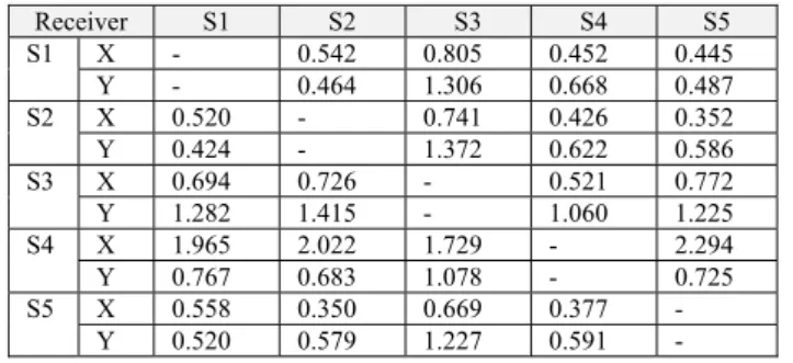
Receiver S1 S2 S3 S4 S5 S1 X - 0.542 0.805 0.452 0.445 Y - 0.464 1.306 0.668 0.487 S2 X 0.520 - 0.741 0.426 0.352 Y 0.424 - 1.372 0.622 0.586 S3 X 0.694 0.726 - 0.521 0.772 Y 1.282 1.415 - 1.060 1.225 S4 X 1.965 2.022 1.729 - 2.294 Y 0.767 0.683 1.078 - 0.725 S5 X 0.558 0.350 0.669 0.377 - Y 0.520 0.579 1.227 0.591 - TABLE 5. INTELLIGENT DIFFERENCE WITH FILTERED DATA
Receiver S1 S2 S3 S4 S5 S1 X - 0.409 0.467 0.339 0.367 Y - 0.382 1.048 0.469 0.308 S2 X 0.412 - 0.457 0.304 0.279 Y 0.383 - 1.062 0.458 0.440 S3 X 0.394 0.425 - 0.261 0.409 Y 1.020 1.074 - 0.820 0.930 S4 X 0.355 0.375 0.531 - 0.263 Y 0.483 0.528 0.968 - 0.594 S5 X 0.430 0.304 0.387 0.278 - Y 0.300 0.407 1.098 0.479 -
The five sensors and their surroundings are presented on Fig. 4. The five sensors are represented with red, green, blue, magenta and cyan colours respectively. The sensor locations are presented with crosses (+) and their
accuracy with ellipses depending on X and Y standard deviation errors.
Fig. 5 presents the GPS instantaneous locations obtained for the five sensors.
From Fig. 6 which represents the accuracy in east and north direction for the five sensors, it is clear that the sensor 3 (blue ellipse) has the worst accuracy. It can be explained by the multi-path errors and limited visibility of the sky. The heights of buildings B1, B2, B3 are approximately 2, 5 and 10 m. The buildings affect the sensor S3 more than the other sensors.
For many applications of GPS, the altitude component is not used especially for vehicle navigation. This component is not discussed in the reminder of this paper.
The first left column in the following tables represents the sensor used as reference station. For each sensor (e.g. S1), X, Y represent East and North directions respectively.
C. Simple Difference Processing
The simple difference consists of subtracting errors measured on the reference sensors in each second. This experiment provides worst results than the original data (without correction) as shown in Table 2. This fact can be explained by two factors:
¾ In our previous experiments [40][41] and [42], the nodes generally have a clear visibility of the sky without building obstructions. In the new experiment, depending on the five sensor locations, each node has its own error, and applying simple difference adds more errors to the locations of nodes, which then increases the standard deviation.
¾ Also, GPS data in the previous experiments is obtained once per second by one-hop direct communications. In the new experiment, with the negative effect of multi-hop, there is some missing data. Consequently, there is delay between the time of reference error and the time when this reference error is really used.
D. Filtering
The second step is applying filtering using EMA (Exponential Moving Average) with α=0.99. The standard deviation of filtered data is lower than the standard deviation of original data. Applying simple difference with filtered data gives better results than the first case, but it is still not sufficient. The number of improvements is less than the number of degradations. The Table 3 shows the results obtained by filtering and applying simple difference on filtered data.
E. Intelligent Difference Processing
The third step is to apply the intelligent difference, which consists of considering error correction as:
¾ The minimum amount of errors of the two reference stations, if the two errors have the same direction (processing each component X and Y separately).
¾ The sum of errors of the two reference stations, if the two errors have different directions (processing each component X and Y separately). The result presented in Table 4 shows that intelligent difference gives more interesting results than filtering. The sensor S5 (cyan) can correct the locations of the other sensors, but the sensor S3 (blue) gives always the worst results.
The forth step is to apply the intelligent difference with filtered data. The Table 5 lists the obtained results.
The Table 5 shows that intelligent difference method combined with filtered data gives the most interesting correction, which is more noticeable than filtering or intelligent difference alone. The sensor S3 always gives the worst results which means that a global view is needed to select which reference station(s) should be used or not. The drawback of intelligent different is that, it can not be applied to mobile nodes, because reference location for mobile nodes does not exist. To overcome this problem, the solution may be to get an average error based on two or more (or all) reference stations using filtered data, and then to use intelligent difference. We call this method as the “Global difference” and our works in this direction are in progress.
V. CIVICIMPLEMENTATION AND EXPERIMENTS
The purpose of our experiments is to implement the CIVIC protocol on a sensor network, test its feasibility and make it reliable. At the same time, the experiments serve also to validate LCD-GPS.
A. Hardware Platform
The hardware platform used in experiments is the LiveNode sensor developed by our team [11]. It is a versatile wireless sensor node, which enables to implement rapidly a prototype for different domains of applications such as telemedicine (wireless cardiac arrhythmias detection sensor for instance), inter-vehicle communication, and environmental data collection.
The LiveNode sensor is a small board (70x55mm) and is powered by a 9V standard battery. It may be equipped with different types of components (GPS, Wi-Fi, ZigBee, GSM and different type of sensors) to meet the requirements of an application. The major components of LiveNode sensor used in our experiments of CIVIC protocol and LCD-GPS have three parts as shown in Fig. 7:
The Atmel AT91SAM7S256 [43][44] microcontroller is used for data processing. It is an ARM7TDMI based high-performance 32-bit RISC microcontroller with Thumb extensions with USB Device Interface, 32 I/O pins, one Advanced Interrupt Controller, one Periodic Interval Timer, two USARTs, 256 K bytes Flash and 64 K bytes SRAM.
The MaxStream XBee Pro [45] chip is to ensure the wireless communication of ZigBee (IEEE802.15.4). The module operates within the ISM 2.4 GHz frequency band. It is cheap ($32), it requires low power (60 mW), and it can reach a wide range (up to 1 mile). The ZigBee is chosen in our new experiments instead of Wi-Fi because
ZigBee has an outdoor RF line-of-sight range up to 1.6 km and an indoor range of 100 m, which is equivalent to Wi-Fi indoor range one. Besides, the energy consumption for ZigBee module is less than the available Wi-Fi modules.
The GlobalSat ET-301 [46] GPS chip is for specific GPS signal processing. It is a 20-channel all-in-view tracking receiver. It communicates on the serial port with the micro-controller at the default baud rate of 4800 bps. The receiver automatically sends its complete message once every second. Then, the micro-controller detects and decodes the message.
B. Software Development
The software of our experiments is mainly written in C, except for hardware-related parts in assembly language. The monitoring software (in Java) is developed specially for our experiments (Fig. 8). The network screenshots and result analysis of this section are got from this monitoring software.
The CIVIC system is driven by three interrupt sources: one from PIT (Periodic Interval Timer) and the other two from USART (Universal Synchronous Asynchronous Receiver Transmitter).
The PIT is set to interrupt at a specified period depending on the task requiring minimum interval. Each task has a separate counter increased by every PIT interrupt. When a counter reaches its predefined limit, it goes back to zero and calls the related task. The major periodic tasks include data processing, neighbour searching, routing requesting, and application data sending.
The USART0 interrupt is occurred when data is received from GPS, and the USART1 interrupt is generated when data is received from ZigBee. The
Figure 7. Hardware platform for experiments.
USART interrupt handlers then transfers the incoming data into their own FIFO buffers for data processing.
C. Network Deployment
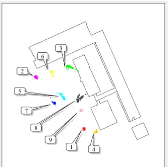
The location of our CIVIC experiments is the same as previous LCD-GPS experiments: the parking (about 70x50 meters) of our campus as shown on Fig. 9. All LiveNode sensors are randomly distributed on the tops of cars. A sensor at the corner is set as the receiver of routing request and application data (original GPS data information in our experiments). The data is recorded by four ZigBee base stations, which are also randomly distributed. The Fig. 10 demonstrates a sample of network deployment when using nine sensors. A sample of network deployment for five sensors is shown in Fig. 4 of section 3.
Because the outdoor radio range of ZigBee Pro is up to 1.6 km and the space available to our experiments is limited, we define a filter for each sensor to remove the packet sent from the distance longer than 40 meters. It forces some sensors to send data in multi-hops, so we can evaluate the efficiency of packet forwarding in CIVIC
protocol. Because each sensor actually receives all packets from the network, if CIVIC protocol can work under this setting, it should perform better in applications that are more practical.
D. Packet Deliver
As previously mentioned, there are three mechanisms when transmitting data in CIVIC protocol. Consequently, there are mainly three groups of packets as shown in Table 6:
TABLE 6. PACKET GROUP FOR CIVIC
Group Packet Name Maximum Size (Byte) Hello PACK_HELLO_REQ_CIVIC PACK_HELLO_RPY_CIVIC 38 45 Routing PACK_ROUTE_REQ_CIVIC PACK_ROUTE_REQ_SF PACK_ROUTE_RPY_CIVIC PACK_ROUTE_RPY_BY_PATH. 45 24 64 44 Application PACK_DATA_SEND PACK_DATA_FWD PACK_DATA_ACK PACK_DATA_ACK_FWD 63 63 25 25
In addition, a packet type of PACK_MANAGEMENT is sent by the ZigBee station for controlling the previous mechanisms and running experiment sections.
Although the CIVIC is a location-based protocol, for practical reasons, it integrates SF technique as a part in the routing process. When there is no position obtained by GPS, the protocol can still perform the routing tasks. The PACK_ROUTE_REQ_SF is designed for this purpose.
Fig. 11 and Fig. 12 show the major dataflow in neighbour knowledge exploration and routing request in CIVIC protocol. In principal, if the source node has the position of destination node, it performs the CIVIC routing request; otherwise, it uses SF to send the position of source node, and asks the destination node reply in the CIVIC routing request.
After at least one routing has been done, the original GPS data will be send to the destination node.
To keep CIVIC protocol adaptable to other MAC, we use only the “Broadcast Mode” provided by ZigBee chip. The IP addressing and data forwarding is done by CIVIC
Figure 9. Location of experiments.
Figure 10. Network deployment for nine sensors. 2 1 6 4 7 8 5 3 9
protocol. It is well known that the neighbourhood broadcasting easily causes collisions. Even if we apply CMSA/CA (with a slotted contention), which is commonly used by most MAC protocols, there will be a probability that two sensors would sense the same slot being free, and transmit data in the same slot [47]. Therefore, the CIVIC protocol must have the additional mechanism in the network layer to minimize the influence from collisions. The PACK_DATA_ACK and PACK_DATA_ACK_FWD are designed for this purpose. Depending on the application requirements, when the destination node receives the data, it can choose to send back an acknowledgement to the source node. If the source node does not receive this acknowledgement, it can thus choose further actions. It is not a standard approach of CIVIC protocol, and its efficiency will be evaluated in our experiments.
E. Three Experiment Scenarios
The first experiment is to compare the DANKAB broadcast with the SF broadcast in the routing process of CIVIC protocol. There are reasons to choose SF in this experiment: SF is reliable in terms of coverage, and it has been practically used in low-density networks. Besides, to compare with two broadcasting methods, they must be implemented on the same hardware platform, and run under the same conditions. Resource constraints of embedded sensor limit the choice of broadcasting methods.
This experiment is done in a static network with nine sensors. The parameters used for evaluations are the overall packet number, the packet loss rate, and the average routing hop distance (the maximum hop is four). In both broadcasts, at five seconds intervals, eight sensors require routing to a single sensor at the corner as shown
Figure 11. Dataflow driven by PIT interrupt.
Figure 12. Dataflow driven by USART1 interrupt.
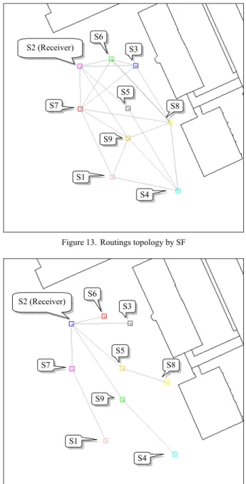
Figure 13. Routings topology by SF
Figure 14. Routing topology by DANKAB S2 (Receiver) S1 S6 S4 S7 S8 S5 S3 S9 S2 (Receiver) S1 S6 S4 S7 S8 S5 S3 S9
in Fig. 13 and Fig. 14. Both DANKAB and SF broadcast stop when 50 routings are found.
TABLE 7. COMPARING SF AND DANKAB Packet Number Packet Loss Rate Average Routing Hop SF 3453 9.13% 2.10 DANKAB 1144 2.97% 1.39
The result of comparison is shown in Table 7. The DANKAB has better performance in all three parameters. Moreover, comparing to SF routing paths as shown in Fig. 13, all DANKAB routing paths are on the right direction to the destination node as shown in Fig. 14.
The second experiment is a comparison of the application packets sending with or without acknowledgement.
The network deployment and the target sensor is the same as in the first experiment. The experiments are run after all sensors obtain routing paths by DANKAB. At one-second intervals, sensors send their original GPS data to the target sensor. The GPS data are wrapped in the application packets. The experiments stop when 100 application packets are sent, thus ideal there should be 800 application packets received by the target sensor.
In the experiment without acknowledgement, all sensors just keep sending until finished. In the experiment with acknowledgement, if an acknowledgement has not been received, the sender assumes that the target sensor is busy, and waits three seconds before sending the data again.
This target sensor (S2) is connected to a laptop by its debug port. The main parameters for comparison are packet number received by debug port, and the overall packet number received by ZigBee stations.
TABLE 8. COMPARING THE EFFICIENCY OF ACKNOWLEDGEMENT
Packet Number (by debug port)
Packet Receiving Rate Overall Packet Number No Ack 773 97% 1043 With Ack 851 100% 2260
The result is shown in Table 8. For the LCD-GPS experiments, the packet receiving rate is satisfied when sending without acknowledgement. Therefore, in the next experiments we use the application packets without acknowledgement.
The third scenario is to evaluate the factor of mobile sensor. It is done in a network with nine sensors. This experiment compares a static network with nine sensors and a similar network with one mobile sensor (Fig. 15).
TABLE 9. COMPARING THE FACTOR OF MOBILE SENSOR
Packet Number (debug port)
Packet Receiving Rate Static Network 773 97%
Mobile Network 652 82%
The result in Table 9 shows that a part of the application data is lost because of the sensor movements, but overall the CIVIC protocol performs well in mobile network. The data analysis after experiments indicates that the packet loss is mainly caused by two reasons: i. Radio interference; ii. The interval for routing request is set to be too short, so the new routing path can not be updated in time.
VI. CIVICAPPLICATION:MOBIPLUS
The CIVIC protocol is used as a prototype to experiment three projects in different areas: inter-vehicle communication (MobiPlus project), environmental data collection (Net-ADDED European project) and telemedicine (LiveCare project). In this paper, we present only the MobiPlus project.
MobiPlus project is supported by the SMTC of Clermont-Ferrand city in France (Syndicat Mixte des Transports en Commun de l’agglomération clermontoise). It focuses on improving the public service on urban transportation system particularly to disabled passengers (Fig. 16).
The MobiPlus has two major components: LNB (LiveNode Bus) and LNS (LiveNode Station). The LNS contains an RFID (Radio-Frequency IDentification) reader, which detects the presence of the disabled passenger who has an RFID electronic ticket. The RFID electronic ticket contains the information about the specific needs of the passenger, and this information will
Figure 15. Experiment with a mobile sensor Receiver S2
Mobile Node S3 (Ending Point)
Mobile Node S3 (Starting Point)
Figure 16. MobiPlus project in Clermont-Ferrand (France) RFID Ticket LNS
LNB
be sent to the bus that he or she is waiting for. Thus, when LNB arrives at LNS, related services according to these specific needs will be provided. For example, if a wheelchair user is present, the wheelchair lift on LNB will be activated. If a sight-deprived passenger is present, the voice notice from LNS will be played.
The LiveNode sensors embedded at LNB and LNS communicate with CIVIC protocol, which adopts Wi-Fi and ZigBee. The GPS is used to localize the LNB and to estimate its arrival time.
VII. CONCLUSION AND ONGOING WORK
In this paper, a new inter-vehicle communication protocol named CIVIC has been described. The CIVIC protocol was implemented on LiveNode sensor, compared to the SF protocol, and tested on different scenarios. The obtained results meet the requirements of the IVC applications in term of performance, robustness and efficiency. This paper has also presented new results of LCD-GPS experiments cooperating with CIVIC protocol. The results confirm the results obtained in previous works especially the use of intelligent difference with filtered data [42].
The cooperating experiments present new challenges on developing CIVIC protocol and LCD-GPS. For the CIVIC protocol, we must continue to improve the efficiency of CIVIC protocol when the LCD-GPS requests higher data rate in communications. For adopting LCD-GPS in practical IVC applications, it is anticipated to have the negative effects of the multi-path, the limited visibility of the sky, and the packet loss in transmissions. The “Global difference” may be a better solution for the problems, but it would need to be proved by further works.
The LCD-GPS will enlarge the application domains of standard civil GPS (e.g. precision agriculture, precision mobile tracking in urban areas, etc.). With the improvement of GPS accuracy, the CIVIC protocol will be implemented on the infrastructure of the V2I (Véhicules et Infrastructures Innovants de la Fédération de Recherche TIMS) project: autonomous intelligent multi-modal electric cars and agricultural vehicles (tractor etc.). The CIVIC protocol will be also used in the Net-ADDED EU project to increase the wireless coverage range around an access medium in the rural area to improve the practice of precision agriculture. Moreover, in a bigger picture, although the CIVIC protocol is originally designed for IVC, its applications are not limited to inter-vehicle communication. With proper modifications, it can be adapted to other applications like smart home, telemedicine, and environment monitoring.
ACKNOWLEDGEMENTS
We would like to thank the EU (NeT-ADDED FP6 EU project), the “Conseil Régional d’Auvergne”, and the French and Chinese governments through PHC PFCC 2009 (20974WG) project for their supports to CIVIC project.
REFERENCES
[1] B. Fitzgibbons, R. Fujimoto, R. Guensler, A. Guensler, M. Hunter, A. Park, and H. Wu, “Simulation-Based Operations Planning For regional Transportation Systems,” in Proc. 5th Annual Nat. Conf. on Digital Government Research: New Challenges and Opportunities, Seattle, May 2004.
[2] B. Fiebig, “European Traffic Accidents and Purposed Solutions,” in Proc. ITU-T Workshop on Standardisation in Telecommunication for motor vehicles, November 2003. [3] J. P. Singh, N. Bamos, B. Srinivasan and D. Clawin,
“Wireless LAN Performance Under Varied Stress Conditions in Vehicular Traffic Scenarios,” in Proc. of IEEE Vehicular Technology Conference, Vancouver, Fall 2002, vol. 2, pp. 743-747.
[4] J. Luo, J. P. Hubaux, “A survey of inter-vehicle communication,” Technical Report IC/2004/04, EPFL, 2004.
[5] I. Chlamtac, M. Conti, and J. Liu, "Mobile Ad Hoc Networking: Imperatives and Challenges," Elsevier Ad Hoc Networks Journal, vol. 1, no. 1, pp. 13-64, July 2003. [6] P. Obreiter, B. Knig-Ries and M. Klein, “Stimulating
Cooperative Behavior of Autonomous Devices – An Analysis of Requirements and Existing Approaches,” Technical Report Nr. 2003-1, March 2003.
[7] H. Elaarag, “Improving TCP performance over mobile networks,” ACM Computing Surveys, vol. 34, n°3, pp. 357-374, 2002.
[8] X. Li, M. R. Lyu and J. Liu, “A Trust Model Based Routing Protocol for Secure Ad-hoc Networks,” in Proc. of IEEE Aerospace Conference, March 2004.
[9] A. Böhm, "State of the Art on Network Layer Aspects for Inter-Vehicle Communication," Technical Report IDE0748, Halmstad University, June 2007.
[10] N. Samama, Global Positioning, Technologies and
Performance, John Wiley & Sons, ISBN:
978-0-471-79376-2, 2008.
[11] K. M. Hou, G. De Sousa, J-P. Chanet, H-Y. Zhou, M. Kara, A. Amamra, et al., “LiveNode: LIMOS versatile embedded wireless sensor node,” in Proc. of Notere’2007, International Workshop on Wireless Sensor Networks, pp. 65-69, Marrakech, Morocco, June 2007.
[12] FleetNet Documents, Available at: http://www.et2.tu-harburg.de/fleetnet/english/documents.html.
[13] W. Franz, H. Hartenstein, and M. Mauve, Eds.,
Inter-Vehicle-Communications Based on Ad Hoc Networking Principles – The FleetNet Project, Universitätsverlag
Karlsruhe, ISBN 3-937300-88-0, June 2005
[14] P. Morsink, R. Hallouzi, I. Dagli, C. Cseh, L. Schäfers, M. Nelisse, et al.: “CarTALK2000: Development of a Co-operative ADAS based on Vehicle-to-Vehicle Communication,” in Proc. of the 10th World Congress and Exhibition on Intelligent Transport Systems and Services, Madrid, ESP, November 2003.
[15] The CarTALK2000 website, Available at: http://www.cartalk2000.net.
[16] S. Tsugawa, “An Introduction to Demo 2000: The Cooperative Driving Scenario,” IEEE Intelligent Systems 15(4): 78-79, 2000.
[17] USDOT, “USDOT Outlines the New VII Initiative at the 2004 TRB Annual Meeting,” Available at: http://www.its.dot.gov.
[18] ITS Joint Program Office, “VII Architecture and Functional Requirements,” Version 1.1, U.S. Department of Transportation, Washington, DC, 2005.
[19] W. J. Franz, H. Hartenstein, B. Bochow, “Internet on the Road via Inter-Vehicle Communications,” GI Jahrestagung (1) 2001: 577-584, 2001.
[20] M. Rudack, M. Meincke, and K.jobmann, “On Traffic Dynamical Aspects of Inter Vehicle Communication,” in Proc. of VTC 2003 (Fall), USA, 2003.
[21] S. Tsugawa, “Issues and recent trends in vehicle safety communication systems,” LATSS Research, 29(1):7–15, 2005.
[22] Y. Shiraki, T. Ohyama, S. Nakabayashi, and K. Tokuda, “Development of an Inter-Vehicle Communications System,” Special Edition on ITS, vol. 68, pp. 11-13, September 2001.
[23] F. M. Aziz, “Implementation and analysis of Wireless Local Area Networks for high-Mobility Telematics,” Master of Science in Electrical Engineering, May 30, 2003. [24] T. Clausen and P. Jacquet, “Optimized Link State Routing
Protocol,” IETF RFC 3626, October 2003.
[25] C.E. Perkins and P. Bhagwat, “Highly Dynamic Destination Sequence-Vector Routing (DSDV) for Mobile Computers,” Computer Communication Review, 24(4), 1994, 234-244.
[26] R. Ogier, F. Templi, and M. Lewis, “Topology dissemination based on reverse-path forwarding (TBRPF).” IETF RFC 3684, February 2004.
[27] D. B. Johnson, D. A. Maltz and J. Broch, “DSR: The Dynamic Source Routing Protocol for Multi-Hop Wireless Ad-hoc Networks,” Ad-hoc Networking, Ed. Addison-Wesley/Charles E. Perkins, pp. 139-172, 2001.
[28] T. Kosch, Ch. Schwingenschlögl and L. Ai, “Information Dissemination in Multihop Inter-Vehicle Networks – Adapting the Ad-hoc On-demand Distance Vector Routing Protocol (AODV),” in Proc. of The IEEE 5th Int. Conf. on Intelligent Transportation Systems, Singapore, 2002. [29] V. D. Park and M. S. Corson, “A Highly Adaptive
Distributed Routing Algorithm for Mobile Wireless Networks,” in Proc. of INFCOM '97, April 1997.
[30] C. K. Toh, “Long-lived Ad-Hoc Routing based on the concept of Associativity,” IETF MANET Working Group, Inter Draft, March 1999.
[31] R. Dube, C.D. Rais, K. Wang and S.K. Tripathi, "Signal Stability based adaptive routing for Ad Hoc Mobile networks," IEEE Pers. Comm., Feb. 1997, pp. 36-45. [32] J. Schaumann, “Analysis of the Zone Routing Protocol,”
Dec. 2002. Available at: http://www.netmeister.org/ misc/zrp/zrp.pdf.
[33] J. Hao, K. M. Hou, J-J. Li, J-P Chanet, C. De Vaulx, H-Y Zhou, et al., "The capacity and packets delivery of MANET On Road: MANETOR," Global Mobile Congress, pp. 553-558, China, 2005.
[34] G. Zhou, T. He, S. Krishnamurthy, and J. A. Stankovic, “Impact of Radio Irregularity on Wireless Sensor Networks,” in Proc. of the 2nd international conference on Mobile systems, applications, and services, pp. 125–138, 2004.
[35] Y-C Tseng, S-Y Ni, and E-Y Shih, “Adaptive Approaches to Relieving Broadcast Storm in a Wireless Multihop mobile Ad-hoc Network,” IEEE transactions on computers, vol. 12, No 5, pp. 545-556, May 2003.
[36] B. Williams and T. Camp, “Comparison of broadcasting techniques for mobile Ad-hoc Networks,” Mobihoc’02, EPFL, pp. 194-205, Switzerland, June 2002.
[37] U.S. Department of Defense, “Standard Positioning System Performance Specification,” October 2001.
[38] A. LaMarca, and E. de Lara, Location Systems: An
Introduction to the Technology Behind Location Awareness, Synthesis Lectures on Mobile and Pervasive
Computing, Vol. 3, No. 1, Pages 1-122, Morgan&Claypool Publishers, ISBN: 978-1-598-29581-8, June 2008. [39] Z. Sahinoglu, S. Gezici, and I. Guvenc, Ultra-wideband
Positioning Systems: Theoretical Limits, Ranging Algorithms, and Protocols, pp. 2-6, New York: Cambridge
University Press, 2008.
[40] M. Kara, K. M. Hou, J-P. Chanet, H-Y. Zhou, M-A. Kang, F. Pinet, “Low Cost Differential GPS receivers (LCD-GPS): Urban vehicle tracking,” I2TS’06 ‘5th International Information and Telecommunication Technologies Symposium’, pp. 16-21, Cuiabá, MT, Brazil, December 2006.
[41] M. Kara, K. M. Hou, J-P. Chanet, H-Y. Zhou, M-A. Kang, F. Pinet, “Low Cost Differential GPS receivers (LCD-GPS): A Local Cooperative Differential GPS solution,” Notere’2007, International Workshop on Wireless Sensor Networks, pp. 29-34, Marrakesh, Morocco, June 2007. [42] M. Kara, K.M. Hou, “Low Cost Differential GPS receivers
(LCD-GPS): The differential correction function,” NTMS’2008, Wireless Sensor Network Workshop, pp. 282-287, Tangier, Morocco, November 2008.
[43] Atmel Datasheet, “AT91SAM7S Series Summary,” 2008, Available at:
http://www.atmel.com/dyn/resources/prod_documents/617 5s.pdf .
[44] Atmel Datasheet, “AT91SAM7S Series Preliminary,” 2008, Available at:
http://www.atmel.com/dyn/resources/prod_documents/doc 6175.pdf .
[45] MaxStream Product Manual, "XBee/XBee-Pro OEM RF Modules," v1.xAx, 2007, Available at: http://ftp1.digi.com/support/documentation/manual_xb_oe m-rf-modules_802.15.4_v1.xAx.pdf .
[46] GlobalSat Technology Corporation, “Product User Manual, Gps Engine Board, ET-301,” Available at:
http://www.sparkfun.com/datasheets/GPS/ET-301%20USER%20Manual1.pdf
[47] J. Tourrilhes, "Robust broadcast: improving the reliability of broadcast transmissions on csma/ca", IEEE International Symposium on Personal, Indoor and Mobile Radio Communications 3, pp. 1111–1115, 1998.
BIOGRAPHIES
Xunxing DIAO is currently a PhD student in
computer science at LIMOS Laboratory of Blaise Pascal University, France. He received the BEng degree in Civil Engineering from Guangdong University of Technology, China, in 2000, and the MSc degree in Information Technology from The University of Nottingham, UK, in 2005. His major research interests include MANET, WSN and inter-vehicle communications.
Messaoud KARA is currently a PhD
candidate in computer science at LIMOS Laboratory of Blaise Pascal University at Clermont-Ferrand, France. He received his engineering and M.S degree in computer science from, respectively, INI (Institut National de formation en Informatique) in Algiers, Algeria (2001) and Versailles University, France (2002). His research interests include localization and routing in wireless ad hoc and sensor networks.
Jian-jin LI was born in China in 1965. She
received her B.Sc. degree in Mathematics from Wuhan University, China in 1987, M.Sc. degree in Computer Science from INSA de Lyon, France in 1989, and she got her PhD degree in Parallel Programming from Ecole Normale Supérieure de Lyon, France in 1992.
She is currently associate professor at ISIMA-Blaise Pascal University. Her research interests are in mobile computing and wireless sensor networks. In particular, she is investigating in communication protocol for Intelligent Transport System and Wireless Sensor Networks.
Kun Mean HOU was born in Cambodia in
1956. He held a PhD degree in 1984 and a HDR degree in 1996 in Computer Science from the University of Technology of Compiègne (UTC).
He worked as associate professor at UTC from 1984 to 1986. In 1986 he joined IN2 as R&D engineer group leader. From 1989 to 1996, he created a research group which investigated parallel architecture dedicated to real-time image processing at laboratory HEUDIASYC UMR CNRS (UTC).
In 1997 he joined the college of engineering school ‘ISIMA: Institut Supérieur d’Informatique de Modélisation et de leurs Applications’ as professor, where he created the SMIR team of the laboratory LIMOS UMR 6158 CNRS (10 researchers) working on the development of basic hardware and software
dedicated to WSN. Different sensor nodes (Bluetooth, WiFi and ZigBee), embedded wireless communication and embedded real-time kernel (SDREAM and LIMOS) are implemented and deployed in different applications such as telemedicine, intelligent transportation system and precision agriculture. He holds 3 EU patents, and he evolved in 3 EU projects and 10 technology transfers. He is also evolved in several scientific committees and boards.
HaiYing ZHOU, associate professor of
Harbin Institute of Technology (China), received his Ph.D. degree at the LIMOS laboratory, university of Blaise Pascal (France) and has done the PostDoc research at the institute of Cemagref (France). His research interests include mobile computing, wearable computing, embedded system and signal processing.
Jacquot Aurélien is currently a PhD
candidate in computer science at Cemagref and LIMOS Laboratory of Blaise Pascal University at Clermont-Ferrand, France. He received his engineering and M.S degree in computer science from ISIMA (Institut Supérieur d’Informatique de Modélisation et de leurs Applications), France, in 2006. His research domain is Wireless Management Tools in Wireless Sensor Networks.