Publisher’s version / Version de l'éditeur:
Vous avez des questions? Nous pouvons vous aider. Pour communiquer directement avec un auteur, consultez la première page de la revue dans laquelle son article a été publié afin de trouver ses coordonnées. Si vous n’arrivez pas à les repérer, communiquez avec nous à [email protected].
Questions? Contact the NRC Publications Archive team at
[email protected]. If you wish to email the authors directly, please see the first page of the publication for their contact information.
https://publications-cnrc.canada.ca/fra/droits
L’accès à ce site Web et l’utilisation de son contenu sont assujettis aux conditions présentées dans le site LISEZ CES CONDITIONS ATTENTIVEMENT AVANT D’UTILISER CE SITE WEB.
International Thermal Spray Conference (ITSC), Québec City, Canada, May
24-27, 2021, 2021-05-24
READ THESE TERMS AND CONDITIONS CAREFULLY BEFORE USING THIS WEBSITE. https://nrc-publications.canada.ca/eng/copyright
NRC Publications Archive Record / Notice des Archives des publications du CNRC :
https://nrc-publications.canada.ca/eng/view/object/?id=5d4cdcf5-ca58-4fb0-a385-67a8d4ad6f5f
https://publications-cnrc.canada.ca/fra/voir/objet/?id=5d4cdcf5-ca58-4fb0-a385-67a8d4ad6f5f
NRC Publications Archive
Archives des publications du CNRC
This publication could be one of several versions: author’s original, accepted manuscript or the publisher’s version. / La version de cette publication peut être l’une des suivantes : la version prépublication de l’auteur, la version acceptée du manuscrit ou la version de l’éditeur.
Access and use of this website and the material on it are subject to the Terms and Conditions set forth at
Novel powder modification method for the cold spray of hard steels
Poirier, Dominique; Thomas, Yannig; Guerreiro, Bruno; Martin, Manuel;
Aghasibeig, Maniya; Irissou, Eric
Novel powder modification method for the cold spray of hard steels
D. Poirier, Y. Thomas, B. Guerreiro, M. Martin, M. Aghasibeig, E. Irissou
National Research Council of Canada, Boucherville, Quebec, Canada
Abstract
A novel powder modification method based on the simultaneous softening and agglomeration of steel powders via heat treatment in a rotary tube furnace has been investigated as a promising way to improve H13 tool steel powder cold sprayability. By adjusting starting powder size and shape as well as heat treatment conditions (maxi-mum temperature, cooling rate and heat treatment atmosphere), cold spray of H13 powder went from virtually no deposition to the production of dense, sound and thick deposits with a powder deposition efficiency of 70%. Powder agglomeration, surface state, microstructure evolution and softening are identified as key factors deter-mining the powder deposition efficiency and resulting deposit microstructure.
Introduction
Cold spray technology is ideally suited for restoring damaged metal parts and components due to its ability to rapidly produce thick and dense deposits displaying high mechanical properties with minimal heat input to the substrate [1]. Cold spray repair development was initiated by the aerospace industry for Al and Al alloys [2] and is now spreading to other fields and materials compositions [2-3].
Steel being the most common engineering material, cold spray of steels is of high interest for several repair applications. Austenitic stainless steels such as 304 and 316 present medium strength and are among the steels showing the highest levels of ductility [4]. Cold spray coating build-up being based on powder deformation, dense deposits of these steels are easily sprayed using helium process gas while deposits with few percent porosity are typically obtained when sprayed with nitrogen or compressed air [5-10]. However, very little can be found about other steel types and more specifically, there is no study in the open literature regarding the cold spray of tool steels that would open the door to new approaches to design changes and repair in the tooling industry while high strength steel would offer opportunity for additive manufacturing and repair of machinery and other industrial components. It is well known that cold spraying hard feedstocks is challenging [11]. With the hardest feedstocks, the maximum achievable coating thickness is limited to a single layer of particles due to the poor deformation of the
hard particles impacting the already deposited hard layer [12-13]. Unsurprisingly, cold spraying of tool steels, specifically designed to resist deformation, is a challenge. One strategy to improve quality of the cold spray deposits produced with hard powders is to focus on the cold spray conditions. An increase in particle velocities through the use of helium (He) as the propelling gas or through increased propelling gas pressure or temperature will increase impact energy, hence particle deformation [11]. An increase in materials temperature (e.g. through powder pre-heating [14], substrate heating [15], laser assisted cold spray (LACS) [16]) will also facilitate particle deformation. However, there are certain limitations in using these aforementioned approaches. Process costs increase drastically with the use of He or with the need for oversized equipment. Also there is ultimately a practical technological limit to the cold spray equipment capabilities. Substrate or powder temperature control, including during LACS, is not straightforward and the heat input may lead to thermal stresses with the possibility of generating cracks and deposit delamination. The increase in temperature can also detrimentally oxidize the substrate surface and/or modify the substrate mechanical properties at the surface due to microstructural changes.
Powder engineering is another approach that presents high potential. It has been shown that porous WC-based agglomerated powder with relatively low particle strength produces denser and thicker cold spray coatings [17-18]. The presence of pores reduces the density of the particles that are then easier to accelerate. Also, the loosely agglomerated and porous particles deform more easily upon impact (pseudo-deformation). However, the particle porosity and/or strength levels have to be carefully adjusted to allow deformation at particle impact while preventing particle fragmentation, thus allowing optimized coating deposition. Two other powder engineering approaches have shown interesting results but are limited to composites. First, it has been found that powders containing nano-size carbides could be deposited while powders with micron-size carbides could only produce a single layer of particles using the same or more elevated conditions. It appears that small carbides can more easily move upon impact, especially if porosity is present, providing more deformation ability [12]. In the case of the hard phase mixed with a softer matrix, the contact between the two phases is also favored with nanosize reinforcement, favoring deposit build-up [12]. Second, it has been shown that pre-coating the surface of WC with Al or Cu, e.g. soft
materials, can significantly improve powder cold sprayability and coating properties [19]. This finding is coherent with cold spray bonding theory based on localized deformation at the surface of particles.
In addition to these methods, hardness of several metallic alloys can be drastically modified through microstructural transformations [20]. However, very few studies have been conducted to adjust alloy powder microstructure to improve the cold sprayability, and these seem to be restricted to Al alloys. Powders are homogenized and quenched to obtain a solid solution microstructure [21-23]. Removal of the cast microstructure is shown to improve powder cold sprayability (increase in deposition efficiency and coating quality) and it potentially eliminates the need to solid solutionize the full deposit prior to the ageing step in the heat treatment performed to optimize part properties. Most tool steels are heat treatable, i.e. their properties can be modified with careful selection of heat treatment parameters. It can therefore be envisioned to anneal the received powder to reduce its hardness as much as possible and make it more deformable during cold spray process. Typical annealing temperature for H13 (bulk) is 845 to 900°C with a maximum cooling rate of 22°C/h and similar values are used for other tool steels [24]. At this temperature, which is above the eutectoid temperature, the matrix is transformed to austenite. Since carbides are more soluble in this phase, carbide dissolution occurs. The steel is then cooled down slowly to prevent the formation of hard martensite, a non-equilibrium and highly strained body-centered tetragonal phase, and to allow the growth of carbides, thus minimizing their strengthening effect. The resulting material is softer and easier to deform. This approach is already used in conventional powder metallurgy [25]. After shaping, the coating or the produced part would need to be heat treated via hardening/tempering stages to raise its hardness to the level required by the application. This development strategy presents the advantage of being simple and requiring readily available equipment.
In this work we report on a new steel powder modification method to improve H13 powder cold sprayability. Powder annealing with and without agglomeration is investigated using two initial H13 powder sizes. Heat treatment temperature, cooling rate and atmosphere are varied and their impact on powder cold sprayability is assessed through microstructure and deposition rate evaluation. The best obtained deposit is heat treated and its hardness after heat treatment is compared with bulk H13.
Experimental Methodology
Feedstock powdersTwo commercially available H13 chromium hot-work tool steel powders from Sandvik Osprey Ltd (Neath, Wales, UK) with particle size distributions nominally of between 10 to 45 µm and <16 µm were used. Herein, the two powders are named as “coarse” and “fine”, respectively. Given compositions of the two powders are shown in Table 1.
Table 1. Chemical compositions of H13 powders.
Type ID Composition Coarse +10 -45 µm C 5.09% Cr, 1.44% Mo, 1.03% V, 0.95% Si, 0.39% Mn, 0.37% C, Fe balance Fine <16 µm F 5.20% Cr, 1.70% Mo, 1.07% V, 1.12% Si, 0.33% Mn, 0.47% C*, Fe balance
*Slightly higher carbon content than the maximum allowable for H13 composition (0.47% instead of 0.45%)
Cold spray process
For initial cold spray trials, rectangular low carbon steel 1020 substrates with dimensions of 76.2 mm x 76.2 mm and thickness of 3.2 mm were used, while for deposition of the coatings intended for post-cold spray process heat treatment (section 4 of the results) N type Almen strips of SAE 1070 steel were used as the substrates. Prior to the coating depositions the substrates were degreased using ethanol and then manually grit-blasted with an air pressure of 0.276 MPa (40 psi) at an approximate blasting distance of 150 mm at 30°, using grit 24 (~975 µm) alumina (Al2O3). In addition, an air gun was used to remove
extraneous alumina particles from the grit-blasted surface. Deposition of coatings was performed using a PCS-1000 cold spray system (Plasma Giken, Tokyo, Japan) equipped with a commercial tungsten carbide converging-diverging nozzle PNFC2-010-30S. Nitrogen was used as the propellant gas and the process parameters are specified in Table 2.
Table 2. Cold spray process parameters. Gas T (°C) Gas P (MPa) SOD (mm) Robot scanning speed (mm/s) Powder feed rate (g/min) # passes 950 4.9 45 100 or 300 15-32 5 or 10
Deposition rates were obtained from the measured coating thickness divided by the number of passes and were normalized for a powder federate of 20 g/min. The deposition efficiency was calculated from the ratio of the weight of the coating measured by weighing the samples before and after spraying to the weight of the powder that is sprayed toward substrate obtained from the measured powder feed rate and the calculated spraying time.
Heat treatment
Two different powder heat treatments were performed. The powders were either heat treated in a 100 mm diameter standard quartz tubular furnace (Lindberg, Riverside, MI, USA) or in a 100 mm rotary quartz tube furnace (model OFT1200X-4-R-IL-UL, MTI Corporation, Richmond, CA, USA) set at 2.5 rpm, while varying the heat treatment time and temperature profile as well as heating atmosphere. Selected cold spray coatings were heat treated in the standard quartz tubular furnace under nitrogen atmosphere at 1200°C for 3 h (austenitizing and sintering) followed by quenching and two steps of martensite tempering at 570°C for 2 h for improved ductility.
The average particle size and the volume-weighted particle size distribution were measured via a laser diffraction particle size analyzer (LS320, Beckman Coulter, Miami, FL, USA).
Deposited coatings were cut perpendicular to the spraying direction. The sectioned samples and the powders were cold vacuum mounted in an epoxy resin and polished according to the standard metallographic preparation procedures using a 0.25 µm colloidal silica suspension for the final polishing step. To reveal the microstructure of the polished samples, Vilella’s reagent (100 ml ethanol, 5 ml hydrochloric acid and 1 g picric acid) and Nital (2 ml HNO3 and 98 ml
ethanol) were used as etchants for powder and cold spray samples, respectively. A field emission gun scanning electron microscope (FEG-SEM S-4700, Hitachi, Tokyo, Japan) was used for characterization of the feedstock powder morphologies in secondary electron imaging mode (SE) and for cross-sectional microstructural analysis of the powders and cold spray coatings before and after heat-treatments in SE or backscattered electron imaging (BSE) modes.
Nanohardness of the powders were evaluated by a MTS Nano Indenter-G200 (Oak Ridge, TN, USA) with a Berkovitch tip under a load of 3 gf. The average nanohardness values were obtained from at least 15 indentations performed on the polished cross-sections of the powders. Hardness of a selected heat-treated coating was measured using a Rockwell C hardness tester (model B2000, Wilson Instruments, now Buehler, Lake Bluff, IL, USA) by averaging 5 indentations taken on the ground surface of the >2 mm thick coating.
Results and Discussion
Coarse H13 powder heat treatment and coating results
The effect of tempering and annealing the powder on the agglomeration and softening is investigated with the following two experimental set of conditions:
Tempering (HT 600°C): Temper the powder under nitrogen at a relatively low temperature to minimize sintering in a standard quartz tubular furnace. Powder was held at 600°C for 4 h under nitrogen and furnace cooled.
Annealing (HT 875°C): The typical annealing temperature for H13 (bulk) being 845-900°C, i.e. above the temperature at which significant sintering can occur. Annealing was performed in a rotary tube furnace to limit powder agglomeration. Powder was held at 875°C for 2 h under nitrogen followed by a slow cool down of 22°C/h until 500°C, and then furnace cooled.
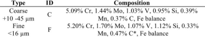
Figure 1 displays the particle size distributions in as-received condition and after the two different heat treatments for the “coarse” powder. Powder caking occurred after HT 600°C even at the selected relatively low temperature and crushing was required to recover the powder. Agglomeration was however less pronounced after HT 875°C performed in the rotary tube furnace and only a
simple mixing in a V-blender was sufficient to break the soft agglomerates and recover most of the powder. Sieving to -45 µm still had to be performed to remove the coarse tail which is not seen on Fig. 1.
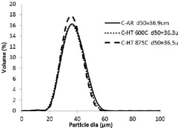
Figure 2 shows the microstructures and nanohardness of the heat treated coarse powder at the two conditions compared to the as-received powder. A network surrounding darker grains is present for the as-received powder microstructure. Gas atomized tool steel powders are subjected to fast cooling rates during their manufacturing, and as such, they are typically composed of retained austenite and martensite [25]. For this reason, the observed grains are believed to be retained austenite and martensite. The network is probably composed of carbides, as typically observed for tool steel as-cast microstructures obtained under high cooling rates [26]. This hypothesis is also in agreement with the high powder hardness obtained (8.1 GPa). Powder microstructure after HT 875°C is composed of spheroidized carbides, the desired morphology to lower hardness and maximize formability. The carbides have precipitated and grown during the slow cooling step of the heat treatment. Owing to the slow cooling rate, martensite formation has also been prevented – grains are most probably composed of ferrite, hence the low hardness value of 3.0 GPa. Powder microstructure after HT 600°C is at an intermediate stage between the as-received and the fully annealed powder microstructures. The temperature of this heat treatment is not high enough for austenitisation but martensite tempering can occur and carbides can slightly evolve. The associated hardness is 6.1 GPa.
Figure 1. Particle size distribution of “coarse” powder (10 to 45 µm), Received, and heat-treated (C-AR: As-Received, C-HT 600°C: heat-treated at 600°C, C-HT 875°C: heat-treated in a rotary tube furnace at 875°C).
(a)
nH = 6.1 GPa nH = 8.1 GPa
(b)
Figure 2. Etched microstructure (SE) and nanohardness of the coarse powder (a) As-Received, (b) HT 600°C and (c) HT 875°C.
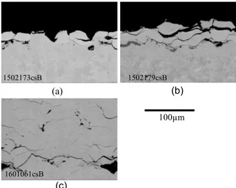
Coarse powder lots were cold sprayed in as-received condition and after heat treatments. The resulting coating microstructures can be seen Fig. 3. As expected, only a single layer of particles could be deposited when using the hard, as-received H13 powder. The heat treatment at 600°C slightly improved powder cold sprayability but the resulting coating is still limited to a thin layer and displays poorly bonded particles on a non-uniformed second layer. The coatings prepared with powder HT at 875°Cand sieved at -45 µm, however, was thick but contained cracks as shown in Fig. 3c.
(a)
(b) (c)
Figure 3. Microstructures (BSE) of deposits produced with H13 coarse powder (a) As-Received (b) HT 600°C (c) HT 875°C (robot traverse speed = 300 mm/s).
These tests demonstrated that H13 powder heat treatment to soften the powder is possible without too much sintering if powders are agitated at high temperature – for instance in a rotary tube furnace. Providing the heat treatment is done in appropriate conditions, powder hardness is reduced by more than 60%, leading to improved powder cold sprayability. However, the resulting coating still presented poor interparticule bonding.
H13 fine powder modification (heat treatment and agglomeration) and coating properties
(a) Initial trials
Effect of powder agglomeration on cold sprayability of H13 is investigated. In order to obtain an agglomerated powder
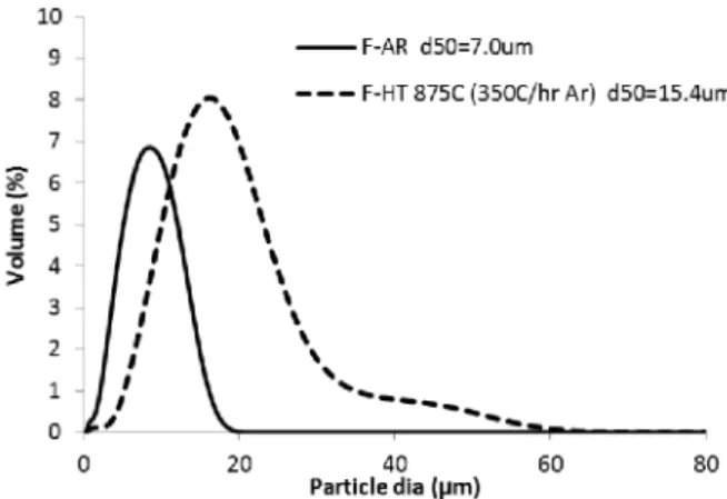
of an appropriate size for cold spray, powder heat treatment was performed using the fine powder (F) with particle size of <16 µm. Heat treatment conditions were adjusted to obtain powder softening as well as adequate powder agglomeration level. Considering the powder caking obtained out of the standard quartz tubular furnace with the coarse powder, only the rotary tube furnace was used to perform the annealing treatment HT 875°C. The powder was then sieved at -45 µm to remove the tail of coarser agglomerates.
As shown in the particle size distributions of Fig. 4, agglomeration was readily obtained with the HT and d50
was increased from 7 to 20 µm, which is an appropriate size for cold spray. This agglomeration is also visible when observing the powder using SEM (Fig. 5). The size of the agglomerates is still smaller (near half) than the size of the coarse powder.
The powder microstructures obtained before and after HT are similar to those obtained for the coarse powder (Fig. 6 vs Fig. 2). Similar to the coarse powder, HT 875°C has also spheroidised the carbides of the fine lot, without any visible decarburization at the powder surface. However, unlike the coarse powder, interparticle bonding was clearly observed with these smaller particles, as shown in Fig. 6b. It is believed that the fine lot is more prone to diffusion and sintering than the coarse one due to its higher surface area [27]. Due to the small powder size, hardness of the particles could not be reliably measured, although it is expected that a significant hardness reduction is obtained after the heat treatment similar to what was observed for the coarse powder.
Figure 4. Particle size distribution of “fine” H13 powder, As-Received and HT 875°C under nitrogen atmosphere.
100µm nH = 3.0 GPa 5µm 1502179csB 100µm 1502173csB 1601061csB (a) (b) (b) (c) (c)
Figure 5. Fine H13 powder (SE) (a) before and (b) after agglomeration by HT 875°C.
Figure 6. Etched microstructures (SE) of fine H13 powder (a) As-Received (b) HT 875°C.
This fine powder was cold sprayed after HT and coating microstructure can be seen Fig. 7. Its normalized deposition rate is compared to the HT 875°C coarse powder in Table 3; twice deposition rate is obtained with the fine powder heat treated under the same conditions. It is hypothesized that this improved cold sprayability is due to the agglomeration process that favors deposition in addition to powder softening. This new method is currently in the process of being patented [28].
Figure 7. Microstructure (BSE) of a deposit produced with H13 fine powder HT 875°C (robot traverse speed = 300mm/s).
(b) Optimization of powder modification process (powder treatment cooling rate and atmosphere)
Two parameters were specially studied for the optimization of the powder modification process: increase in cooling rate to shorten heat treatment duration, and heat treatment atmosphere. The heat treatment cooling rate was increased to 350°C/h. A better control of heat treatment atmosphere oxygen level was provided by the use of high-purity (HP) argon (5 ppm O2max) instead of nitrogen and an improved
tracking and suppression of rotary furnace leaks. These changes did not result in a significant difference in powder microstructure (Fig. 8a). It is to be noted that the limit of 22°C/h for the cooling rate of bulk H13 is fixed not only to avoid martensite formation but is also taking into consideration other aspects which are irrelevant for powder heat treatment, such as heat transfer through thick parts or part cracking/distortion. However, extensive powder
agglomeration was obtained due to lower powder oxidation favoring sintering. In order to remove the powder from the tube and break the largest agglomerates, a pestle and mortar had to be used, resulting in a decrease in the final agglomerate size to d50= 15.4 µm (Fig. 8b and 9).
A drastic improvement in coating uniformity as shown in Fig. 10 was obtained with these powder modification parameters. The deposition rate was also significantly higher with 381 µm/pass yielding to a measured deposition efficiency of 70% (Table 3). This is attributed to the minimisation of powder oxidation during the heat treatment. A thinner surface oxide layer is known to facilitate the powder cold spray deposition and particle bonding [29,30].
(a) (b)
Figure 8. Fine H13 after agglomeration by HT 875°C in Ar (SE) (a) Etched microstructure (b) Morphology.
Figure 9. PSD of fine H13 powder before and after HT 875°C under argon atmosphere and cooled at 350°C/h in pure argon. 5µm 100µm 100µm 1601072csB 5µm (a) (b)
Figure 10 Microstructures (BSE) of a H13 deposit sprayed using fine powder HT 875°C under argon atmosphere and cooled at the rate of 350°C/h(robot traverse speed = 100 mm/s).
Table 3. Powder deposition rates (coarse vs agglomerated fine powders). ID HT atm. HT CR (°C/h) DR (µm/pass)* Comments C-HT 875°C N2 22 42 Cracked coating F-HT 875°C N2 22 78 Sound coating F-HT 875°C
HP Ar 350 381 Sound coating DE: 70%
* normalised for a feed rate of 20 g/min.
Coating microstructures before and after heat treatments
The best coating, i.e. the coating produced with the fine powder modified under argon, was heat treated to be more representative of an in-service state.
Figure 11 shows the etched microstructures of the deposit before and after heat treatment. For the as-sprayed coating, the boundaries of the deposited splats are clearly visible after etching, indicating imperfect particle bonding. Contrary, these boundaries are not visible after heat treatment at 1200°C, demonstrating sintering of the particles at high temperature. The pores shown in the micrograph after heat treatment are believed to be created during the sintering process, when poorly bounded interfaces break into isolated pores, followed by pore coalescence, coarsening and rounding due to surface diffusion [27]. The microstructure of the heat treated deposit is composed of lenticular features indicative of martensite [24], while if carbides are present, they are too small to be observed.
Heat treated deposit hardness was measured at 56.2 HRC, which is comparable to bulk tempered H13 at 38-53 HRC [25]. The deposit microstructure and hardness demonstrate that the cold sprayed H13 deposits are heat treatable and confirm their great potential for several applications.
(b)
Figure 11. Etched microstructures (SE) of deposits produced with fine powder modified under argon (a) As-Sprayed (b) after post spray heat treatment.
Conclusions
In this study, a novel powder modification method based on powder heat treatment in a rotary tube furnace was developed to drastically improve the cold sprayability of H13 tool steel powder. This powder in as-received condition could not be deposited. The use of a fine powder during the powder heat treatment allowed simultaneous annealing and agglomeration of fine particles, which was found to be more efficient than powder annealing alone. This was illustrated by deposition of low quality thin coatings when annealed coarse powder was sprayed. Powder heat treatment temperature (875°C tested in this study) and protective atmosphere exempt of oxygen were found to be key parameters governing cold spray feedstock quality, while cooling rate shows some flexibility and could be increased from 22°C/h (typical for cooling bulk H13) to 350°C/h for increased process productivity. Resulting H13 deposit was found to be receptive to hardening and tempering heat treatment, with a final hardness of 56.2 HRC equivalent to bulk H13.
Acknowledgements
The authors would like to acknowledge the work of the technical officers’ team in Boucherville, namely R. Bouchard (powder treatment and characterization), J.-F. Alarie (coatings production), D. de Lagrave (metallographic sample preparation), S. Mercier (coating heat treatment) and K. Théberge (SEM images, nanoindentation).
References
[1] I. Botef and J. Villafuerte, Modern Cold spray;
Materials, Process and Applications, Springer (2015),
p 1-29.
[2] V.K. Champagne, et al., Modern Cold spray; Materials,
Process and Applications, Springer(2015), p 341-376.
[3] S. Yin, et al., “Cold Spray Additive Manufacturing and Repair: Fundamentals and Applications”, Additive
Manufacturing, Vol. 21 (2018), p 628-650.
[4] S. Srikanth, et al., “Property Enhancement in Metastable 301LN Austenitic Stainless Steel through Strain-Induced Martensitic Transformation and its Reversion (SIMTR) for Metro Coach Manufacture”,
1802062csB
20µm 100µm
International Journal of Metallurgical Engineering,
Vol. 2, No. 2 (2013), p 203-213.
[5] S. Adachi and N. Ueda, “Formation of Expanded Austenite on a Cold-Sprayed AISI 316L Coating by Low-Temperature Plasma Nitriding”, Journal of
Thermal Spray Technology, Vol. 24, No. 8 (2015),
p1399-1407.
[6] P. Coddet, et al., “Mechanical Properties of Thick 304L Stainless Steel Deposits Processed by He Cold Spray”,
Surface and Coatings Technology, Vol. 277 (2015), p
74-80.
[7] R. Huang, et al., “The Effects of Heat Treatment on the Mechanical Properties of Cold-Sprayed Coatings”,
Surface and Coatings Technology, Vol. 261 (2015), p
278-288.
[8] A. Sova, et al., “Cold Spray Deposition of 316L Stainless Steel Coatings on Aluminium Surface with Following Laser Post-Treatment”, Surface and
Coatings Technology, Vol. 235 (2013), p 283-289.
[9] K. Spencer and M.X. Zhang, “Optimisation of Stainless Steel Cold Spray Coatings using Mixed Particle Size Distributions”, Surface and Coatings Technology, Vol. 205, No. 21-22 (2011), p 5135-5140.
[10] G. Sundararajan, et al., “The Elastic Modulus of Cold Spray Coatings: Influence of Inter-splat Boundary Cracking”, Journal of Thermal Spray Technology, Vol. 22, No. 8 (2013), p 1348-1357.
[11] T. Schmidt, et al., “From Particle Acceleration to Impact and Bonding in Cold Spraying”, Journal of
Thermal Spray Technology, Vol. 18 (2009), p 794-808.
[12] A.S.M. Ang, et al., “Deposition Effects of WC Particle Size on Cold Sprayed WC-Co Coatings”, Surface and
Coatings Technology, Vol. 205, No. 10 (2011), p
3260-3267.
[13] P.H. Gao, et al., “Influence of substrate hardness transition on built-up of nanostructured WC-12Co by cold spraying”, Applied Surface Science, Vol. 256, No. 7 (2010), p 2263-2268.
[14] H.J. Kim, et al., “Fabrication of WC-Co Coatings by Cold Spray Deposition”, Surface and Coatings
Technology, Vol. 191, No. 2–3 (2005), p 335-341.
[15] M. Fukumoto, et al., “Effect of Substrate Temperature on Deposition Behavior of Copper Particles on Substrate Surfaces in the Cold Spray Process”, Journal
of Thermal Spray Technology, Vol. 16, No. 5-6 (2007),
p 643-650.
[16] D. Christoulis and C. Sarafoglou, Modern Cold spray;
Materials, Process and Applications, Springer (2015),
p 275-302.
[17] T. Sonoda, et al., “Super Hard WC Cermet Coating by Low Pressure Cold Spray Based on Optimization of Powder Properties”, Proc International Thermal Spray
Conference – ITSC 2013, Busan, Korea (2013), p
241-245.
[18] P.H. Gao, et al., “Influence of Powder Porous Structure on the Deposition Behavior of Cold-Sprayed WC-12Co Coatings”, Journal of Thermal Spray
Technology, Vol. 17, No. 5-6 (2008), p 742-749.
[19] J. Wang and J. Villafuerte, “A novel method to spray tungsten carbide using low pressure cold spray technology”, Ceramic Transactions, Vol. 203 (2009), p 161-168.
[20] W.D. Callister, Materials Science and Engineering An
Introduction, 5th edition, Wiley (2000), 871 pages.
[21] A. Sabard, et al., “Microstructural Evolution in Solution Heat Treatment of Gas-Atomized Al Alloy (7075) Powder for Cold Spray”, Journal of Thermal
Spray Technology, Vol. 27, No. 1-2 (2018), p 145–158.
[22] W.A. Story and L.N. Brewer, “Heat Treatment of Gas-Atomized Powders for Cold Spray Deposition”, ,
Metallurgical and Materials Transactions A, Vol. 49,
No. 2 (2018), p 446–449.
[23] T. Liu, et al., “Effect of Heat Treatment on the Al-Cu Feedstock Powders for Cold Spray Deposition”,
Metallurgical and Materials Transactions A, Vol. 50,
No. 7 (2019), p 3373-3387.
[24] ASM vol. 4 Handbook; Heat Treating, ASM (1991), p.1554 & p.2148.
[25] J.R. Davis, Tool Materials, ASM Specialty Handbook (1995), 501 pages.
[26] J. Hufenbach, et al., “Effect of Short-Term Tempering on Microstructure and Mechanical Properties of High-Strength FeCrMoVC”, Acta Materialia, Vol. 60, No. 11 (2012), p 4468-4476.
[27] R.M. German, Powder Metallurgy Science, Metal Powder Industries Federation (1994), 472 pages. [28] D. Poirier, P.E. Mongeon, Y. Thomas, E. Irissou. WO
2019/016779 A1 Method for Preparing Powders for a cold spray process, and powders therefor.
[29] C.J. Li, et al., “Influence of Spray Materials and their Surface Oxidation on the Critical Velocity in Cold Spraying”, Journal of Thermal Spray Technology, Vol. 19, No. 1-2 (2010), p 95-101.
[30] K.H. Ko, et al., “Influence of Oxide Chemistry of Feedstock on Cold Sprayed Cu Coatings”, Powder