Publisher’s version / Version de l'éditeur:
Vous avez des questions? Nous pouvons vous aider. Pour communiquer directement avec un auteur, consultez la première page de la revue dans laquelle son article a été publié afin de trouver ses coordonnées. Si vous n’arrivez pas à les repérer, communiquez avec nous à PublicationsArchive-ArchivesPublications@nrc-cnrc.gc.ca.
Questions? Contact the NRC Publications Archive team at
PublicationsArchive-ArchivesPublications@nrc-cnrc.gc.ca. If you wish to email the authors directly, please see the first page of the publication for their contact information.
https://publications-cnrc.canada.ca/fra/droits
L’accès à ce site Web et l’utilisation de son contenu sont assujettis aux conditions présentées dans le site LISEZ CES CONDITIONS ATTENTIVEMENT AVANT D’UTILISER CE SITE WEB.
IEEE Journal of Translational Engineering in Health and Medicine, 7, 2018-12-25
READ THESE TERMS AND CONDITIONS CAREFULLY BEFORE USING THIS WEBSITE.
https://nrc-publications.canada.ca/eng/copyright
NRC Publications Archive Record / Notice des Archives des publications du CNRC :
https://nrc-publications.canada.ca/eng/view/object/?id=828005d7-a5aa-4680-9573-dc70ad32681d
https://publications-cnrc.canada.ca/fra/voir/objet/?id=828005d7-a5aa-4680-9573-dc70ad32681d
Archives des publications du CNRC
This publication could be one of several versions: author’s original, accepted manuscript or the publisher’s version. / La version de cette publication peut être l’une des suivantes : la version prépublication de l’auteur, la version acceptée du manuscrit ou la version de l’éditeur.
For the publisher’s version, please access the DOI link below./ Pour consulter la version de l’éditeur, utilisez le lien DOI ci-dessous.
https://doi.org/10.1109/JTEHM.2018.2889496
Access and use of this website and the material on it are subject to the Terms and Conditions set forth at
Pre-clinical translation of second harmonic microscopy of meniscal
and articular cartilage using a prototype nonlinear microendoscope
Baskey, Stephen J.; Andreana, Marco; Lanteigne, Eric; Ridsdale, Andrew;
Stolow, Albert; Schweitzer, Mark E.
Received 16 August 2018; revised 5 November 2018; accepted 30 November 2018. Date of publication 25 December 2018; date of current version 16 January 2019.
Digital Object Identifier 10.1109/JTEHM.2018.2889496
Pre-Clinical Translation of Second Harmonic
Microscopy of Meniscal and Articular Cartilage
Using a Prototype Nonlinear Microendoscope
STEPHEN J. BASKEY1,2,3, MARCO ANDREANA4, ERIC LANTEIGNE2, ANDREW RIDSDALE 3,
ALBERT STOLOW3,5,6, AND MARK E. SCHWEITZER7
1Faculty of Medicine, University of Ottawa, Ottawa, ON K1H 8M5, Canada 2Department of Mechanical Engineering, University of Ottawa, Ottawa, ON K1N 6N5, Canada
3Emerging Technologies Division, Molecular Photonics Group, National Research Council Canada, Ottawa, ON K1A 0R6, Canada 4Center for Medical Physics and Biomedical Engineering, Medical University of Vienna, 1090 Vienna, Austria
5Department of Physics, University of Ottawa, Ottawa, ON K1N 6N5, Canada 6Department of Chemistry, University of Ottawa, Ottawa, ON K1N 6N5, Canada 7Department of Radiology, Stonybrook University, Stony Brook, NY 11794, USA
CORRESPONDING AUTHOR: A. RIDSDALE (andrew.ridsdale@nrc-cnrc.gc.ca)
This work was supported by a Joint Grant from the Natural Sciences and Engineering Research Council of Canada and the General Electric Health Care Canada under Grant CRDPJ 428327 2011.
This paper has supplementary downloadable material available at http://ieeexplore.ieee.org, provided by the author.
ABSTRACT Previous studies using nonlinear microscopy have demonstrated that osteoarthritis (OA) is
characterized by the gradual replacement of Type II collagen with Type I collagen. The objective of this study was to develop a prototype nonlinear laser scanning microendoscope capable of resolving the structural differences of collagen in various orthopaedically relevant cartilaginous surfaces. The current prototype developed a miniaturized femtosecond laser scanning instrument, mounted on an articulated positioning system, capable of both conventional arthroscopy and second-harmonic laser-scanning microscopy. Its optical system includes a multi-resolution optical system using a gradient index objective lens and a customized multi-purpose fiber optic sheath to maximize the collection of backscattered photons or provide joint capsule illumination. The stability and suitability of the prototype arthroscope to approach and image cartilage were evaluated through preliminary testing on fresh, minimally processed, and partially intact porcine knee joints. Image quality was sufficient to distinguish between hyaline cartilage and fibrocartilage through unique Type I and Type II collagen-specific characteristics. Imaging the meniscus revealed that the system was able to visualize differences in the collagen arrangement between the superficial and lamellar layers. Such detailed in vivo imaging of the cartilage surfaces could obviate the need to perform biopsies for ex vivo histological analysis in the future, and provide an alternative to conventional external imaging to characterize and diagnose progressive and degenerative cartilage diseases such as OA. Moreover, this system is readily customizable and may provide a suitable and modular platform for developing additional tools utilizing femtosecond lasers for tissue cutting within the familiar confines of two or three portal arthroscopy techniques.
INDEX TERMS Arthroscopy, cartilage, collagen, diagnostics, histology, microscopy, orthopaedics,
osteoarthritis, second harmonic imaging, and surgical assist devices.
I. INTRODUCTION
Diagnostic arthroscopy is essential in orthopaedics to pro-vide rapid information about numerous symptomatic and asymptomatic structural abnormalities known to be involved in, and important to, the fundamental etiology, progression, and characterization of osteoarthritis (OA). Currently, for progressive and degenerative cartilage diseases, there are limited options for surgeons concerning treatments for the repair of meniscal and articular cartilage lesions [1]–[3]. Wide-spread adoption of repair techniques has also been
limited by the ability to fully assess the health, integration, and functionality of the repaired tissue. As such, new and innovative microscopic visualization techniques are needed to improve the understanding of the disease’s pathogenesis and success of current treatments.
While the potential of non-invasive imaging techniques has been emerging from clinical studies to assess OA-associated bony features and other quantitative parameters such as volumetric assessments of joint space [4], direct visualiza-tion of the tissues in the knee through arthroscopy remains
the true ‘‘gold standard’’ in diagnosing cartilage, meniscus, and ligament pathologies in routine clinical settings [4]–[6]. Radiological measurements and observations of joint space, new bone formation, marrow edema, and hyaline cartilage formation may prove useful, but currently do not provide microscopic resolution and require histological validation with actual specimens of cartilage and bone [2]. Because of the limitations posed by non-invasive radiological measure-ments, the reliance on biopsies, frequently obtained during second-look arthroscopy, is prevalent. These biopsies pro-vide the means to collect biomechanical, genetic, immuno-histochemical, and biochemical information about the car-tilage. Although biopsy excisions are small, on the order of 2 mm [2], they still serve as a possible source of cartilage degradation, and are disconcerting to both the patient and physician.
In the effort to obviate biopsies for diagnostics of car-tilage health, there is increased interest in the translational potential of non-destructive, arthroscopically-available (min-imally invasive) real-time-microscopy techniques. Short-pulse (sub ps) laser scanning techniques, such as second harmonic generation (SHG) and two-photon-excited fluo-rescence (TPEF) of autofluofluo-rescence, enables the visualiza-tion of tissues using endogenous contrast. Optical coherence tomography (OCT) and laser scanning confocal arthroscopy with continuous wave lasers, sometimes utilizing exogenous dyes, offer superior resolution compared to macroscopic imaging techniques such as wide-field arthroscopy, ultra-sound, computed tomography (CT), or magnetic resonance imaging (MRI) [7]–[12]. In particular, the development of portable SHG microendoscope proof-of-concept devices has spiked in recent years because of its suitability to the acquisi-tion of sub-micron resoluacquisi-tion images in un-stained tissues. Several fully portable and hand-held prototypes have been presented for dermatological applications [13]–[15]. These portable SHG skin microscopes lack the ability to image deep tissues, but provide an excellent platform to non-invasively address issues such as motion artefacts [13].
It is well known in biology and medicine that SHG can be used to image collagen fibrils. Further, its potential to study orthopaedically relevant materials such as cartilage, bone, and tendons under static and dynamic conditions has been previously recognized [8], [16]–[23]. As a polarization dependent technique, SHG microscopy is capable of resolv-ing the orientation of collagen fibres [18], [22], [23] and can demonstrate the sub-micron differences in collagen structures in regions of damage [18], [19], [24] or repair [25]. For example, it has previously been observed, through controlled polarization SHG, that advanced degenerative joint diseases like OA are characterized by Type I collagen replacing Type II collagen, which means that load bearing hyaline cartilage is being replaced with tissue similar to fibrocartilage (i.e. elastin fibres) [9], [21].
It has also been proposed that features visualized through nonlinear microscopy can be coupled with related optical properties like birefringence and biattenuance that relate to
material properties. Moreover, additional fluorescent probes can be used independently to evaluate tissue health, cell death, and matrix diffusivity [7], [8], [21], [24]. Presently, this level of detail is only obtainable after histopathologi-cal examination of biopsy samples using multiple immuno-histochemical staining techniques [2]. Further clinical con-text is available in the supplemental materials (section I).
Diagnostically, nonlinear optical microscopy has notable potential because of the similarity between observations with micrographs obtained through classical histology [26]–[30]. In particular it has been proposed that nonlinear microscopy may be used as a biopsy guidance tool that may also reduce the requirement for biopsies [27], [28] and increase the accu-racy of surgical margins [31], [32]. In cartilage, the spa-tial resolution of nonlinear optical microscopy techniques is capable of imaging local tissue damage, cell density, colla-gen alignment, and morphological features in cartilage [7], [8], [21], [24]. Of particular interest, a recent study into early stage OA by Kumar et al. [8] demonstrated that SHG microscopy reliably identified changes in the extracellular matrix (ECM) of excised human cartilage with grade-I OA. This study identified microsplits and wrinkles from thick tissue sections and classified these as new and novel mor-phological features, which are not detectable using CT, MRI, ultrasound, and (conventional) arthroscopy.
Medical positioning devices as surgical adjuncts have also been developed with augmented optics and enhanced ergonomics [33] for specialized functions such as for nasal surgery [34] and uterus positioning robots for laparoscopic hysterectomy [35]. Other more complex systems such as the Zeus system (Computer Motion Inc.), or the da Vinci system (Intuitive Surgical Inc.) have also been developed for complex multi-purpose surgeries [33], [36].
This report details the development and testing of a portable, arthroscopic, nonlinear optical microendoscope (PALOMINO) prototype system. The current prototype uti-lizes a miniaturized laser scanning instrument and a mechan-ical positioning system with 6-degrees of freedom (DOFs) to combine the capabilities and functionalities of real-time imaging using a wide-field arthroscope and a nonlinear opti-cal microscope in a single device. This study demonstrates the stability and suitability of the prototype PALOMINO system to image orthopaedically relevant surfaces from arbi-trary angles using fresh, minimally processed, partially intact porcine knee joints.
II. TECHNOLOGY & METHODS
The PALOMINO system prototype was designed to introduce a dual function arthroscopic tool for orthopaedic microscopy with advanced clinical potential featuring: (i) a custom designed articulated positioning arm to provide maximum stability and manoeuvrability of the arthroscopic tool (ii) a nonlinear laser scanning system designed to generate images of cartilage from second harmonic collagen signals without the need for a contrast agent; (iii) a custom designed opti-cal system utilizing a rigid needle gradient index (GRIN)
lens (designed and optimized for infrared (IR) excitation at 1035 nm and collection at 517.5 nm) and additional optics implemented to control specific chromatic aberrations to optimize the collection of respective SHG signals and wide-field images; (iv) a fibre optic bundle (FOB) surrounding the GRIN lens to improve the collection of back scattered SHG signals and provide arthroscopically relevant illumi-nation when operating in macroscopic-wide-field mode for conventional arthroscopy; and (v) a multi-resolution optical telescope to improve macroscopic arthroscopic capabilities using the GRIN lens.
FIGURE 1. Photograph of the complete mounted PALOMINO system prototype on an optical bench. On the left, the computer chassis holds the control card and power supplies for the two-axis galvanometric scanning mirrors, and the PMT power supply. The PALOMINO scan-head is mounted on the articulated positioning arm. The scope (GRIN-FOB sheath assembly) is enlarged in the upper-right inset. The articulated positioning arm extends towards the middle of the frame from the extruded rail support post to which it is affixed. The articulating mirror assembly, providing constant enclosed laser delivery, is affixed to the scan-head and extends out of frame.
The PALOMINO system prototype (photographed in Fig. 1) consists of three primary components: (i) the articulated 6-DOF spatial positioning system (PALOMINO positioning-arm); (ii) the laser scanning microendoscope (PALOMINO scan-head); and (iii) the scope (GRIN lens and FOB sheath assembly).
A. DESIGN OF THE PALOMINO POSITIONING-ARM
The mechanical articulated positioning arm features 6-DOFs, a coarse working radius of 1 m, and fine position control system integrated directly between the articulated positioning arm and the PALOMINO instrument. The DOFs and coarse working radius were designed to facilitate the examination of cartilage in the human knee in an operating theatre. Other joints such as the shoulder may also be possible however deeper joints such as the hip may require a specialized end-effector.
To position the endoscope for arthroscopic microscopy the mechanical positioning system must: (i) be mechanically stable; (ii) be able to support the arthroscopic scan head securely; (iii) be manoeuvrable in a functional and effective
manner with similar DOFs to conventional unmounted arthroscopes being handled in a clinical scenario; and (iv) propagate minimal vibrations to enable the acquisition of clean high resolution SHG micrographs.
FIGURE 2. CAD models of the articulated 6-DOF PALOMINO positioning-arm. (A) demonstrates the complete 6-DOF articulating PALOMINO positioning-arm in an upright resting position. Each mechanical component providing a DOF is marked red. The three pin joints of the articulating arm ψ1, ψ2, and ψ3provide redundant 3-DOF
planar positioning of the PALOMINO scan-head. (B) demonstrates the 3-DOFs of the end-effector wrist comprised of a linear track mounted to a ring carriage for controlling the scan head’s orientation and approach. θ, ϕ, and 1 (including δ) represent the spatial positioning motion of the wrist, the rotation around a common centre along the ring, and the linear travel of the track to position the PALOMINO scan-head, respectively. The workspaces of the GRIN needle objective, for seven discrete positions of θbetween 0 and 30◦, are depicted by the green conical half-shells. The
cone height is determined by the location 1 of the instrument mounting platform positioned along the linear track. The shell’s radius is determined by the carriage’s location ϕ on the semicircular rail. Pivoting around these end-effector pins, the arch can rotate approximately 270◦
about its radial axis θ. The intersection of the conical shell workspaces is the location of the insertion point of the GRIN needle.
The positioning system, depicted in Fig. 2A is composed of a 3-DOF end-effector connected to a redundant 2-segment 3-DOF arm providing a coarse working radius of 1 m in a horizontal plane. Redundancy in the arm was introduced to facilitate the operation and placement of the PALOMINO system in constrained environments. The end-effector wrist, to which the PALOMINO scan-head is mounted, is comprised of a linear track (UtiliTrack; HepcoMotion, Tiverton, Devon, UK) that is subsequently fixed to a ring carriage mounted to a semicircular rail (HD Ring with V edge; HepcoMotion), using a similar configuration to the previously developed uterus positioning systems [35]. The ring carriage provides approximately 110◦of rotation (ϕ). The instrument mounting
platform of the end-effector includes a carriage that fits within the linear track which provides approximately 8 cm of out of plane travel (1). Fine focus control (δ) was obtained using a linear actuator connected to each of the 1-carriage and the manual positioning brake. The instrument mounting platform affixes to a thin semi-circular arch via a carriage. The geome-try of the carriage has been selected to permit approximately 170◦ of GRIN lens rotation. The arch, attached to the
end-effector by the two red pins depicted in each computer-aided design (CAD) model (Figs. 2A and 2B), is sufficiently large to accommodate a patient’s knee. Specific positioning details for the end-effector, carriage, and GRIN lens workspace are provided in Fig. 2.
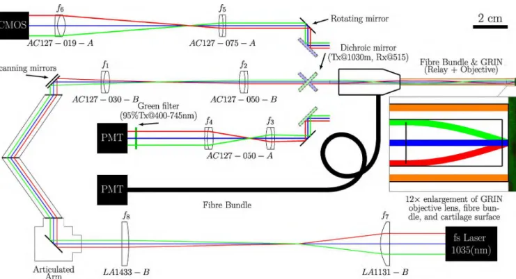
FIGURE 3. Scaled optical schematic of the PALOMINO system. Schematic representation of experimental setup for SHG imaging based on: (i) a pulsed femtosecond laser; (ii) a telescope to reduce the beam diameter and collimate the laser beam; (iii) an articulated mirror assembly providing free space laser delivery; (iv) a two-axis scanning mirror; (v) a scan lens telescope to expand the beam and focus it on the back aperture of the GRIN (vi) a GRIN lens doublet with a FOV of 400 µm (enlarged portion demonstrates the GRIN objective lens with a working distance of 300 µm); (vii) a fibre optic bundle (FOB) for improved collection of the back-scattered signal when optical fibres (orange) surrounding the GRIN are in contact with the sample; (viii) a dichroic mirror/beamsplitter (green shaded representation is associated with the PMT acquisition of SHG signals back-propagated through the GRIN while the blue shaded representation is associated with the wide-field CMOS camera acquisition); (ix) a rotating mirror to switch between the collection of visual wide-field or SHG signals on a camera or PMT, respectively; (x) a telescope to collimate and correct the chromatic aberrations in the
back-propagated SHG signals (f3& f4); and (xi) a telescope providing multi-resolution magnification capabilities to the wide-field FOV imaged by the
GRIN (f5& f6). Block representations of the laser, PMTs, camera, and articulated mirror assembly for laser delivery are not to scale.
B. OPTICAL CONFIGURATION AND CONTROL OF THE PALOMINO SCAN-HEAD
The prototype laser scanning endoscope developed during this study (full optical schematic depicted in Fig. 3) was constructed using: (i) one of two mode-locked femtosec-ond lasers: either a PolarOnyx Uranus 1030-050-0300(CC) High Energy Femtosecond Yb Fibre laser (PolarOnyx laser, Inc., San Jose, CA; 1035 nm, 500 mW, 28 MHz, 300 fs pulse width); or the non-tunable output from an InSightTMDeepSeeTMdual-output option solid-state laser (Spectra Physics, Santa Clara, CA; 1040 nm, 500 mW, 80 MHz, 200 fs pulse width); (ii) an articulated mirror assembly which provides a fully enclosed path for safe laser delivery at a constant distance (Laser Mechanisms, Inc. Novi, MI); (iii) a two-axis galvanometric scanning mirror (Cat No. 6210H; Cambridge Technology, Bedford, MA); (iv) a rigid needle,
multi-element GRIN lens assembly (manufactured by GRINTECH GmbH, Jena, Thuringia, Germany); (v) a cus-tom protected arthroscopic FOB (78 individual fibres: 100 µm silica core; 110 µm clad silica clad, 125 µm polyimide coating; 0.37 NA; 350-2400nm) designed with and manufactured by Fibertech Optica, Kitchener, ON; (vi) standard optomechanical parts obtained primarily from
Thorlabs (Thorlabs Inc, Newton, NJ) and Newport (Newport Corporation, Irvine, CA); and (vii) additional mounts and miniaturized components designed and built by the authors. Micrographs produced from the small, highly portable, Yb-based fibre laser (PolarOnyx) were indistinguishable from those collected with the solid-state laser.
The microscopic imaging capabilities of the PALOMINO system are based on laser scanning (i.e. an optical system that focuses the laser to a point on the sample which is then raster scanned by a two-axis scanning mirror), similar to confocal microscopy. The optical system of the PALOMINO prototype utilized commercially manufactured GRIN lenses to provide similar performance capabilities to intravital fluorescence microscopes and conventional arthroscopes.
The complete PALOMINO system was used to position the arthroscopic GRIN probe perpendicularly to the sur-face of interest for all samples regardless of whether the samples were part of an intact joint or dissected. Accu-rate and high-speed control of the raster scan, performed by the galvanometric scanning mirrors, and data acquisi-tion was achieved using version r4.2n of ScanImage [37], a simultaneous-sampling multifunction data acquisition control unit (NI PCI-6110; National Instruments, Vaudreuil-Dorion, QC), and a shielded connector block with BNC
connectors for analog input/output (BNC-2110; National Instruments). SHG signals were collected using photomul-tiplier tube (PMT) modules (H10723-01; Hamamatsu Pho-tonics K.K., Hamamatsu City, Shizuoka Prefecture, Japan). Gain (voltage) was controlled using a custom program written in MATLAB (MATLAB 7.11.0 (R2010b); MathWorks Inc., Natick, MA) via a USB 2.0 full-speed analogue input and digital I/O data acquisition device (USB-1408FS; Measure-ment Computing Corporation, Norton, MA). A 1 mm thick 12.5 mm diameter longpass dichroic mirror/beamsplitter with extra extended reflection and extended transmis-sion, (Reflectance: 515 nm; Transmittance: 1030 nm; Cat No. T950LPXXRXT-UF1; Chroma, Bellows Falls, VT) is positioned in the emission path at 45◦to the GRIN to isolate
SHG signal from the IR signal. The acquired images were stored as tif files and processed using custom scripts written for FIJI [38].
C. DESIGN OF A GRADIENT INDEX LENS BASED OPTICAL SYSTEM
The optical system was designed and optimized for 1035 nm excitation light, a pitch (number of internal images formed within the lens) of one, and a working distance of 300 um in water and infinity on the image side, using ZEMAX (ZEMAX-EE Optical Design Program (version June 9, 2009); ZEMAX Development Corporation, Bellevue, WA). The optimized GRIN doublet consisted of a 0.5 NA 4.6 mm long objective lens and a 0.1 NA 102.3 mm long relay lens (glued together using optical grade ultra violet (UV) adhe-sive) with an outer diameter of 2 mm. The telescope/relay configuration of optical elements f1and f2in Fig. 3 improve
the flatness of the SHG image and the uniformity of the scan while also magnifying the scanned laser beam on the back aperture of the GRIN lens (relay) by a factor of 1.67. Lastly, for the protection of the GRIN lens during operation, the GRIN needle was fixed with clear acrylic nail polish inside a 12.5 gauge stainless steel hypodermic tube/needle designed to fit within the 2.54 mm FOB. The 3.76 mm final outer diameter of the endoscopic laser delivery and dual-acquisition-path system was designed to be under 4.5 mm for compatibility with commercially available arthroscopic sheaths [39]. Further information about the design and spec-ifications of GRIN lenses is available in the supplemental information (section II).
D. PALOMINO PERFORMANCE TESTING
Testing of the PALOMINO system included experiments uti-lizing minimally prepared and secured porcine joints demon-strating the clinical relevance of the PALOMINO system’s resolution to distinguish characteristics of elastic, hyaline, and fibrocartilage. The load bearing cartilaginous surfaces of interest in clinical pathologies of the knee joint, imaged in the present study, include the menisci, the femoral and tibial condyles, and the patella. The acquisition of clear micrographs of the various cartilaginous components and surfaces from minimally processed, immobilized, and staged
porcine knee joints is intended to demonstrate the stabil-ity and versatilstabil-ity of the PALOMINO system prototype on a clinically relevant model. To assist with interpretations and comparisons with other studies, SHG micrographs were obtained by imaging unmounted sections of human chon-dral flaps from patients with femoroacetabular impingement (FAI). In addition to the main cartilaginous surfaces, mono-potassium phosphate (KH2PO4, KDP) powder was used to
evaluate the performance of the FOB because it produces strong SHG signals from discrete crystal agglomerates and was not embedded in a dense highly scattering media. Addi-tional details concerning KDP controls are available in the supplemental material (section IV).
Further testing qualifying the resolution and performance of the GRIN lens in macroscopic- and microscopic-wide-field imaging was assessed using a United States Air Force 1951 (USAF51) resolution test chart. Images were magni-fied approximately 4 times and focused onto a monochrome complementary metal-oxide semiconductor (CMOS) cam-era (DCC1545M; Thorlabs Inc.). The smallest discernible lines, where calibrated measurements were in agreement with the standardized line widths, were used as our maximum wide-field resolution. Images were calibrated with repeated measurements of known line widths for 6 elements with 1-2 groups visible in each image. Repeated width samplings were averaged per line and element and convergence was assessed based on a calibration factor common to the unique elements in the visible groups. During this process a 150 Watt dual output illuminator (MI-150 High Intensity Illuminator; Edmund Optics, Barrington, NJ) was coupled to a collimating lens coupled to the FOB to provide forward illumination to the GRIN objective lens and diffuse illumination to the back of the USAF51 resolution test chart.
Complete intact porcine knee joints from the back legs of 6 twelve-month-old pigs (200–300lbs) were obtained from a local slaughterhouse within 24 hours post-mortem, stored at 4
◦C, and imaged over the subsequent 24 hours. Minimal efforts
to constrain the tibial segment were made during imaging to preserve clinically relevant DOFs and mobility. Additional details about considerations provided during sample process-ing are available in the supplemental material (section III). Images of fresh, minimally processed, partially intact joints were collected to assess the capabilities of the wide-field acquisition pathway to return low-contrast images compa-rable to those expected during joint arthroscopy. As above, the FOB surrounding the GRIN objective provided forward illumination of the joint surfaces. For increased biological contrast, visible spectrum light was returned to a colour CMOS camera (DCC1645C; Thorlabs Inc.).
III. RESULTS & DISCUSSION
A. FEMTOSECOND LASERS IN OPTICS AND SURGICAL INSTRUMENTS
Currently, the family of Yb-based fibre lasers operating around the 1035 nm wavelength range is an excellent choice for the excitation source of a portable nonlinear laser
scanning microendoscope as they offer among the best price– performance ratios in short pulsed lasers as well as provid-ing robust potential in fibre couplprovid-ing for non-rigid delivery alternatives. While not explored during the present study, laser ablation is another surgical application for related laser systems and could potentially be implemented simul-taneously in a microendoscope [40]–[42]. Laser ablation techniques are most commonly utilized in in vitro cell or tis-sue studies, ophthalmology and dentistry, but research in otology/otolaryngology, dermatology, onychology, and urol-ogy is also conducted [41], [42]. Interestingly, femtosecond lasers have even been investigated as a cutting implement in orthopaedic applications offering significant reductions in tissue debris, necrosis, and contact induced pain [43], [44]. Numerous studies using femtosecond laser ablation in bone and nail tissue have demonstrated no thermal dam-age/stress or cracking, nor any reports of changes in chem-ical composition of the bone-mineral constituents [41], [45]. It has been reported, however, that using femtosecond lasers can lead to a delay in healing, possibly due to bone-surface carbonization [45] or the lack of mechanical stresses that stimulate bone remodelling.
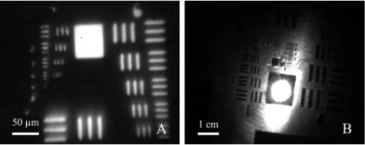
FIGURE 4. Evaluation of the multi-resolution wide-field capabilities of the rigid GRIN probe using a USAF51 resolution test chart. Images were acquired using a black and white CMOS camera. (A) The highest resolution images easily reproducible with the PALOMINO system resolved to 181 line pairs per millimetre or an individually resolved line thickness of 2.76 µm as depicted in the visibility of the standardized lines of the USAF51 resolution test chart (group 7, element 4). (B) Wide-field image acquired in a dark room 2 cm ± 2 mm away from the target illuminated only by the fibre optic bundle (FOB). From this working distance the optical system made visible 10.08 line pairs per millimetre or an individually resolved line thickness of 49.91 µm as depicted in the visibility of the standardized lines of the
USAF51 resolution test chart (group 3, element 3).
B. ARTHROSCOPIC PERFORMANCE DURING WIDE-FIELD IMAGE COLLECTION
Using working distances much smaller than those typically used in clinical arthroscopy, the smallest reproducible line-width of 2.76 µm (group 7, element 4) during the wide-field resolution tests using the USAF51 resolution test chart (see Fig. 4A) were limited by the distance between the GRIN objective and the target because the GRIN objective was inset (by approximately 100 µm) in the 12.5 gauge stainless steel hypodermic needle. This resolution is lower than the smallest visible line-width of 775 nm (USAF51 resolution test target group 9, element 3) reported by Rivera et al. [46]; however, without a contrast agent and/or oblique or dark
illumination techniques, specular reflection from cartilage provides insufficient contrast to provide clinically relevant details using wide-field arthroscopy at this resolution. Thus, when directly approaching the surface to within a few hun-dred microns, the required contrast to preserve depth percep-tion (remaining distance to the target) and orientapercep-tion will be lost. We anticipate that this system will be best used during a two or three portal arthroscopy technique which will allow a second endoscope to be used for advanced viewing of the GRIN probe on approach to the surface.
Operating like a standard arthroscope, relevant working distances between the tip of the scope to the tissue surface are on the order of many millimetres to a few centimetres. When acquiring macroscopic fields of view (FOVs), the GRIN objective must be separated from the sample by a few cen-timetres. With a multi-resolution system numerous levels of magnification are possible; however, much remains to be optimized [47]. When positioned 2 cm from the target one configuration of the optical system was able to resolve lines as small as 49.91 µm thick (group 3, element 3 of USAF51 res-olution test chart; Fig. 4B). With the proper illumination, this resolution should be adequate for a clinician to assess tears, lesions, and extrusions in cartilaginous joint structures. In addition, the illumination provided to the target at this working distance was adequate to illuminate sub-millimetre features; however, the centre focus and forward conical illu-mination patterns visible in Fig. 4B could likely be improved using fibres with a larger numerical aperture (NA). It is also possible that increasing the NA of the fibres would increase the SHG collection capabilities of the FOB [48], [49].
Conventional arthroscopes are hand-held, and as such, their ability for repeatable detailed observations and/or precise quantitative measurements of tears, lesions, and extrusions in cartilaginous joint structures in real-time may be limited compared to the high resolution potential for a mounted device such as the one in the present study. The present study did not employ a disease model so images of the cartilaginous joint structures are expected to be compa-rable to healthy joints and other medical porcine arthroscopy validation studies [50], [51]. A considerable level of detail, including striations in the ligaments (Fig. 5), was visible. Macroscopically, extensive contrast around the features of the knee was visible during this mock arthroscopic ses-sion on the knee joint which will more than adequately allow the user to navigate through the joint and position the microendoscope to approach the surface to acquire SHG micrographs.
Overall, Figs. 4 and 5 demonstrate that the PALOMINO system is a multi-resolution capable device with wide-field functionality comparable to existing arthroscopes. The short focal length lenses of arthroscopes provide entocentric (fish-eye) perspectives with large FOVs where the centre of the field has higher magnification than the periphery. Large FOVs have the potential to improve navigation ability and visualization of certain cartilaginous defects/features in the joint; however this must be accounted for if quantitative
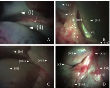
FIGURE 5. Wide-field GRIN-probe-arthroscopy of the internal anatomy of a porcine knee joint. (A) superior anterior aspect of the knee: (i) posterior patella; and (ii) anterior patellar surface of the femur. (B) anterior aspect of the knee: (iii) anterior medial femoral condyle; (iv) anterior medial meniscus; (v) anterior lateral femoral condyle; (vi) anterior lateral meniscus; (vii) anteromedial anterior cruciate ligament (ACL);
and (xv) connective tissue. (C) inferior anterior medial knee articulation: (iii) anterior medial femoral condyle; (iv) anterior medial meniscus; (vii) anteromedial ACL; and (viii) transverse ligament emerging from the medial meniscus; (D) posterior aspect of the ligaments of the knee (ligaments of the joint capsule): (ix) posterior medial femoral condyle; (x) posterior medial meniscus; (xi) posterior lateral femoral condyle; (xii) posterior cruciate ligament (PCL); (xiii) posterior meniscofemoral ligament (PML); and (xiv) Wrisberg ligament (portion of the PML).
measures are to be collected. Very little distortion of this type was evident in Figs. 4 and 5 using the current multi-resolution GRIN setup. As observed in Figs. 4B and 5, shad-ows appeared to be one of the strongest factors affecting the level of visible diagnostic detail.
C. PERFORMANCE AND CLINICAL SIGNIFICANCE OF THE PROTOTYPE PALOMINO SYSTEM, SHG MICROGRAPH ACQUISITION, AND PORTABLE MICROENDOSCOPES
The articulated PALOMINO positioning arm was designed to accommodate the size of a human knee and there were no complications when the porcine limb was used as a substi-tute. Additionally, the large working radius of the articulated PALOMINO positioning arm may increase its clinical suit-ability as it will be large enough to be part of a self-contained portable system that can easily be moved or retrieved. This device is similar to the Jenlab MPTFlex device which offers multi-photon imaging to dermatological applications on a positioning system with multiple DOFs. Additionally, to the best of our knowledge, this study is among the first to not rely on high precision multi-DOF positioning platforms to provide fine control of the specimen relative to the portable microendoscope while also not remaining in direct contact with the sample.
Clinically, precise quantifications about size, depth, and the exact location of cartilage damage, including lesions and extrusions, are often very important during diagnosis
and when considering treatment options. Therefore, SHG microendoscopy may require pairing with additional radi-ological techniques to provide a more complete diagnostic understanding [52].
The present study was conducted on porcine joints, an ani-mal model that has been used for arthroscopic training [50], [51] and for studying articular cartilage, ligament, and meniscal degeneration [53], [54]. Unlike previous studies [50], [51], the porcine limbs collected from local butchers already had the majority of all muscle and skin removed making joint inflation and lavage impractical, and as such, small amounts of connective tissue needed to be removed. This made it easier to monitor the probe on approach and adjust the articulated PALOMINO positioning arm to match the planes of the sample and the GRIN objective. Since this will not be the case in clinical arthroscopy a second perpendicular arthroscope to provide a view of the microen-doscope’s approach will likely be necessary. Naturally, the rigid nature of the probe makes it unsuitable for many types of endoscopy which are traditionally carried out with flexible endoscopes; however, in orthopaedic arthroscopy, rigid GRIN needles have excellent potential.
It is also important to note that the GRIN lens was designed to be an immersion objective. Because an irrigation system that would also inflate the joint was not used during the imag-ing sessions, immersion conditions were generated usimag-ing either completely submerged samples, or running small vol-umes of liquid down the GRIN probe, to be wicked between the surfaces of the probe and the cartilage. No differences were evident between images acquired from either immersion method.
Given the clinical importance for continuing studies into the pathologies and etiologies of cartilage degeneration, this study attempted to acquire SHG images of any surfaces that are primarily composed of Type I or Type II collagen and are load bearing or may be a target of clinical treatment/repair for any of the pathologies previously introduced. Components of the joint to which SHG visualization may prove of significant clinical interest include: the meniscus (Figs. 6A to 6D); the patella (Figs. 7 and 8A to 8C); the femoral condyles (Fig. 8E); the tibial condyles (Fig. 8F); the femoral head (Fig. 8D); and the ligaments (Figs. 6E and 6F).
Both Type I and Type II collagen are prominent con-stituents in meniscal and articular cartilage, tendons and liga-ments. Type II collagen is the primary constituent of articular (hyaline) cartilage, constituting more than 90–95% [55]. The meniscus (fibrocartilage) are made of more than 90% Type I collagen [56]. Type I collagen is also the primary constituent of ligaments which may also contribute to their similarities to fibrocartilage and why ligaments of the knee even have zones of fibrocartilage [57].
The micrographs generated using the PALOMINO microendoscope demonstrated its capability to resolve the differences between hyaline cartilage (i.e. articular cartilage covering the posterior surface of the patella, femoral and tibial condyles, and femoral head (Fig. 8)) and fibrocartilage
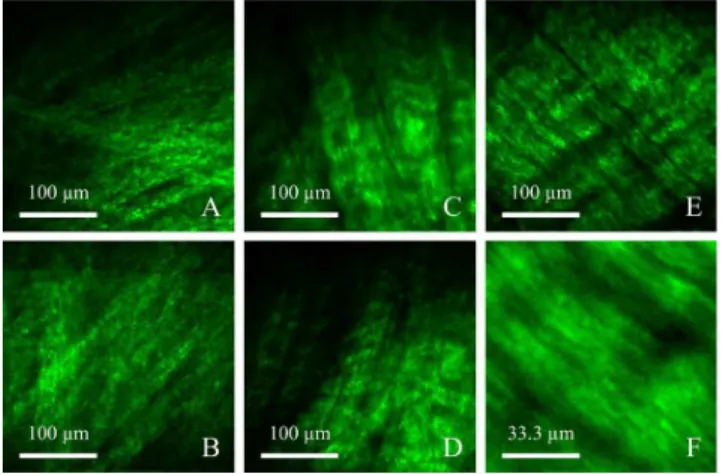
FIGURE 6. SHG micrographs of softer tissues comprised of primarily Type I Collagen. (A–D) depict SHG micrographs of meniscal microstructure from the femoral side of a thick curved portion of a submerged and immobilized meniscus. (E–F) depict SHG micrograph of ligament microstructure from an internal porcine knee ligament. Type I collagen microstructures visible in the acquired SHG micrographs included: (A–B) dense randomly oriented collagen fibres, possibly from the superficial network zone of the meniscus; (C–D) highly structured, aligned, layered, and crimped collagen fibres, possibly from the lamellar zone of the meniscus; (E) aligned Type I collagen fibrils (consistent with fibrocartilage) of an internal porcine knee ligament; and (F) internal porcine knee ligament from the same FOV as E with a scan magnification of 3×.
FIGURE 7. SHG micrographs of hyaline cartilage from: (A) highly structured porcine patella with clear voids from chondrocytes and lacunae; (B) highly structured porcine patella from the same FOV as A with a scan magnification of 2×; (C) highly structured porcine patella from the same FOV as A with a scan magnification of 3×. The apparent similarities in perceivable structures, signal clarity, and background noise indicate that the optical resolution has reached a practical limit specific to the current optical design, alignment, and calibration.
(i.e. meniscus (Fig. 6)) through unique Type I and Type II collagen specific characteristics and structures. Interestingly, the lack of extra texture and detail evident across Fig. 7, which are from the same region of interest (ROI) of the patella but with increasing magnification ratios of 1:2 and 1:3 acquired during the scan, indicates that the resolution used under normal conditions, using the current optical configuration and calibration, has plateaued. This digital zoom capability may be used to visualize ROIs without excessive increases in noise. Some of the most feasible changes/optimizations to improving the resolution and overcoming this plateau, without redesigning the optical system and changing the size of the FOV, include improving the signal-to-noise ratio of the laser, controlling wavelength polarity, introducing beam-splitting phase compensation, and possibly combin-ing multiple nonlinear optical imagcombin-ing techniques such
FIGURE 8. SHG micrographs of hyaline cartilage from: (A) highly structured porcine patella with clear voids from chondrocytes and lacunae; (B–C) regions of the patella which may have experienced higher loading as voids from chondrocytes and lacunae are less defined, possibly compacted; (D) porcine femoral head with similar void composition to B & C; and (E–F) porcine femoral and tibial condyles, respectively, with similar void composition to B–D; suggesting a possible load dependent relationship in clarity of extracellular matrix (ECM) voids in the absence of resolvable collagen fibril alignment and orientation consistent with previous transmission electron microscopy (TEM) imaging and biomechanical testing [59].
as TPEF. Many of these design choices are already included in complex bench top microscopes, or custom optical setups, which have resolved tiny structural details pertinent to understanding the pathogenesis of degenerative cartilage disorders [8], [18]–[24].
Additionally, for the potential application of meniscus diagnostics and repair evaluation, it is encouraging that struc-tural distinctions were visualized in each of the top two zones of the fibrocartilage structure of the meniscus. Specifically, the superficial network zone and deeper lamellar zone were identifiable through their characteristic collagen structures. Figs. 6A and 6B clearly depicted the superficial network zone on the femoral side of the meniscus surface, which is characterized by a random meshwork of Type I collagen fibres within the top 10 µm [8], [58]. Figs. 6C and 6D were highly representative of the deeper lamellar zone, which is characterized by tight fibre bundles of crimped collagen intersecting at various angles [58]. Interestingly even the ligaments visualized in Figs. 6E and 6F were representative of the central main layer of the meniscus (fibrocartilage) [58] suggesting that the ligament FOV visualized may have been a zone of fibrocartilage [57].
It is also interesting to observe the potential correlation in the contrast between the chondrocytes and lacunae (voids of SHG signal) and the surrounding ECM of hyaline car-tilage and the loading and wear the surface may experi-ence (a phenomenon already observed in the patellar groove of articular cartilage [59]). Specifically, there are regions of the patella which show excellent visualization of the ECM and chondrocytes (Figs. 7A and 8A). However, con-trast between the chondrocytes and the surrounding ECM decreases in different regions of the patella (Figs. 8B and 8C).
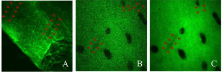
FIGURE 9. SHG micrographs of hyaline cartilage from a fixed slice of acetabular chondral flap excised from the impinging area of
femoroacetabular impingement (FAI) during surgery of a (human) patient. The excised chondral flap specimen presented elongated voids that could represent microsplits, lesions, or regions of damage in the cartilage (arrows). These features demonstrated that the resolution of this prototype endoscope may be suitable for clinical applications. It should be noted however, that these features were approaching the minimum detectable size and could be lost due to noise if too many frames were averaged over as demonstrated between figures B and C.
Chondrocyte-ECM contrast continues to further decrease with the femoral head (Fig. 8D) and most significantly with the tibial and femoral condyles (Figs. 8E and 8F), surfaces which absorb significant impact loads and millions of artic-ulation cycles. It is possible that the decrease in contrast is a function of matrix stiffness [59], load, and wear, which may be causing the surface layer containing the voids (chon-drocytes and lacunae) to be compacted, worn down, and/or be comprised of a different fibril arrangement ultrastructure [59]. Additional information about the collagen fibrils may have been possible; however, for this study, a larger FOV was selected to provide clinicians with a sufficiently large FOV to compare native cartilage with transplanted, engi-neered, or stimulated cartilage.
As previously introduced, SHG microscopy has demon-strated that early stage OA is accompanied by tears and wrin-kles in the ECM [8]. While these features were not expected to be observed in young healthy pigs, the selected FOV size and image quality of the PALOMINO arthroscope’s optical system were expected to be sufficient to resolve microsplits, but not wrinkles, in human articular cartilage similar in size to those imaged by Kumar et al. [8]. Further study would also be needed to assess the validity of porcine cartilage disease models because of the difference in chondrocyte size and other anatomically relevant factors.
The present study included a preliminary SHG microen-doscopic investigation into human acetabular cartilage from the site of an excised FAI. While these samples were not part of an OA study, they also were not considered a healthy control sample to patients with OA. No comparable healthy human acetabular cartilage was available for comparison. As a FAI is a condition of mechanical interference, there may have been similarities in the types of damage observed between OA and FAI; although this comparison requires further study. Despite the differences in the optical setup, micrographs presented by Kumar et al. [8] of the articular surface at depths of 15 and 30 µm were comparable to the micrographs acquired using the PALOMINO endoscopic
prototype, from a potentially damaged, thin, histologically mounted, human cartilage specimens (Fig. 9). These superfi-cial structural changes within the first hundred microns of the cartilage may be valuable in assessing functional condition of the tissue.
IV. CONCLUSION
This work has demonstrated the capabilities of a clinically relevant nonlinear laser scanning microendoscope prototype with the functionality of both an arthroscope and micro-scope capable of imaging minimally-processed partially-intact porcine knee joints. The prototype PALOMINO imag-ing system developed in the present study has validated that GRIN lens doublets increase the feasibility of arthroscopic microscopy. The resolution and image quality of the currently designed system were able to distinguish between hyaline cartilage and fibrocartilage and unique Type I and Type II collagen specific features. The stability of the optical system and the positioning system were sufficient to acquire images with micron scale resolution while preserving the freedom and flexibility to approach the surface from any angle. The similarity in orthopaedically relevant collagen structures obtained on high resolution bench top setups and GRIN-based micro-endoscopes using small, portable, Yb-doped lasers will increase the relevance of ex vivo studies of disease models as the observations will be directly comparable in vivo during diagnostic arthroscopy. The capabilities of this tech-nology are also readily customizable, indicating this system may provide a suitable platform from which to expand the surgical capabilities of femtosecond lasers from diagnostics to treatments within the familiar confines of two or three portal arthroscopy techniques.
ACKNOWLEDGMENT
The authors would like to thank Dr. Andrew Speirs and Dr. Paul E. Beaulé for providing the human cartilage samples; Denis Guay and Doug Moffatt for their time and technical expertise; and the NRC machine shop for their assistance in manufacturing numerous components for the arthroscope.
REFERENCES
[1] J. P. Benthien, M. Schwaninger, and P. Behrens, ‘‘We do not have evi-dence based methods for the treatment of cartilage defects in the knee,’’
Knee Surg., Sports Traumatol., Arthroscopy, vol. 19, no. 4, pp. 543–552,
Apr. 2011.
[2] C. Hoemann et al., ‘‘International cartilage repair society (ICRS) recom-mended guidelines for histological endpoints for cartilage repair studies in animal models and clinical trials,’’ Cartilage, vol. 2, no. 2, pp. 153–172, Apr. 2011.
[3] J. N. Katz, S. A. Brownlee, and M. H. Jones, ‘‘The role of arthroscopy in the management of knee osteoarthritis,’’ Best Pract. Res. Clin. Rheumatol., vol. 28, no. 1, pp. 143–156, Feb. 2014.
[4] A. Guermazi, D. Hayashi, F. W. Roemer, and D. T. Felson, ‘‘Osteoarthritis: A review of strengths and weaknesses of different imaging options,’’
Rheumatic Disease Clin., vol. 39, no. 3, pp. 567–591, Aug. 2013.
[5] L. C. Biant, M. J. McNicholas, A. P. Sprowson, and T. Spalding, ‘‘The surgical management of symptomatic articular cartilage defects of the knee: Consensus statements from United Kingdom knee surgeons,’’
[6] M. Falah, G. Nierenberg, M. Soudry, M. Hayden, and G. Volpin, ‘‘Treat-ment of articular cartilage lesions of the knee,’’ Int. Orthopaedics, vol. 34, no. 5, pp. 621–630, Jun. 2010.
[7] K. D. Novakofski, S. L. Pownder, M. F. Koff, R. M. Williams, H. G. Potter, and L. A. Fortier, ‘‘High-resolution methods for diagnosing cartilage damage in vivo,’’ Cartilage, vol. 7, no. 1, pp. 39–51, Aug. 2015. [8] R. Kumar, K. M. Grønhaug, C. L. Davies, J. O. Drogset, and M. B. Lilledahl, ‘‘Nonlinear optical microscopy of early stage (ICRS grade-I) osteoarthritic human cartilage,’’ Biomed. Opt. Express, vol. 6, no. 5, pp. 1895–1903, May 2015.
[9] B. He, J. P. Wu, T. B. Kirk, J. A. Carrino, C. Xiang, and J. Xu, ‘‘High-resolution measurements of the multilayer ultra-structure of articular car-tilage and their translational potential,’’ Arthritis Res. Therapy, vol. 16, no. 2, p. 205, Mar. 2014.
[10] X. Li et al., ‘‘High-resolution optical coherence tomographic imaging of osteoarthritic cartilage during open knee surgery,’’ Arthritis Res. Therapy, vol. 7, no. 2, pp. R318–R323, Jan. 2005.
[11] F. de Bont et al., ‘‘Evaluation of single-impact-induced cartilage degen-eration by optical coherence tomography,’’ Biomed. Res. Int., vol. 2015, pp. 1–11, Jun. 2015, Art. no. 486794,10.1155/2015/486794.
[12] S. S. Chauhan et al., ‘‘Confocal laser endomicroscopy,’’ Gastrointestinal
Endoscopy, vol. 80, no. 6, pp. 928–938, Dec. 2014.
[13] B. Sherlock et al., ‘‘Fibre-coupled multiphoton microscope with adaptive motion compensation,’’ Biomed. Opt. Express, vol. 6, pp. 1876–1884, May 2015.
[14] A. Krolopp et al., ‘‘Handheld nonlinear microscope system comprising a 2 MHz repetition rate, mode-locked Yb-fiber laser for in vivo biomedical imaging,’’ Biomed. Opt. Express, vol. 7, no. 9, pp. 3531–3542, Aug. 2016. [15] M. Balu et al., ‘‘In vivo multiphoton microscopy of basal cell carcinoma,’’
JAMA Dermatol., vol. 151, pp. 1068–1074, Oct. 2015.
[16] I. Freund, M. Deutsch, and A. Sprecher, ‘‘Connective tissue polarity. Opti-cal second-harmonic microscopy, crossed-beam summation, and small-angle scattering in rat-tail tendon,’’ Biophys. J., vol. 50, no. 4, pp. 693–712, Oct. 1986.
[17] P. J. Campagnola and L. M. Loew, ‘‘Second-harmonic imaging microscopy for visualizing biomolecular arrays in cells, tissues and organisms,’’ Nature
Biotechnol., vol. 21, no. 11, pp. 1356–1360, Nov. 2003.
[18] C. P. Brown et al., ‘‘Imaging and modeling collagen architecture from the nano to micro scale,’’ Biomed. Opt. Express, vol. 5, no. 1, pp. 233–243, Dec. 2013.
[19] C. P. Brown, M.-A. Houle, M. Chen, A. J. Price, F. Légaré, and H. S. Gill, ‘‘Damage initiation and progression in the cartilage surface probed by nonlinear optical microscopy,’’ J. Mech. Behav. Biomed. Mater., vol. 5, no. 1, pp. 62–70, Jan. 2012.
[20] H. Kiyomatsu et al., ‘‘Quantitative SHG imaging in osteoarthritis model mice, implying a diagnostic application,’’ Biomed. Opt. Express, vol. 6, no. 2, pp. 405–420, Feb. 2015.
[21] A. T. Yeh et al., ‘‘Nonlinear optical microscopy of articular cartilage,’’
Osteoarthritis Cartilage, vol. 13, no. 4, pp. 345–352, Apr. 2005.
[22] R. Ambekar, T.-Y. Lau, M. Walsh, R. Bhargava, and K. C. Toussaint, Jr., ‘‘Quantifying collagen structure in breast biopsies using second-harmonic generation imaging,’’ Biomed. Opt. Express, vol. 3, no. 9, pp. 2021–2035, 2012.
[23] M. M. Kabir, V. V. G. K. Inavalli, T.-Y. Lau, and K. C. Toussaint, Jr., ‘‘Application of quantitative second-harmonic generation microscopy to dynamic conditions,’’ Biomed. Opt. Express, vol. 4, no. 11, pp. 2546–2554, Nov. 2013.
[24] J. C. Mansfield, C. C. P. Winlove, J. J. Moger, and S. J. Matcher, ‘‘Collagen fiber arrangement in normal and diseased cartilage studied by polarization sensitive nonlinear microscopy,’’ J. Biomed. Opt., vol. 13, no. 4, p. 044020, Jul./Aug. 2008.
[25] K. A. Ross et al., ‘‘Comparison of three methods to quantify repair cartilage collagen orientation,’’ Cartilage, vol. 4, no. 2, pp. 111–120, Apr. 2013.
[26] S. W. Perry, R. M. Burke, and E. B. Brown, ‘‘Two-photon and second harmonic microscopy in clinical and translational cancer research,’’ Ann.
Biomed. Eng., vol. 40, no. 2, pp. 277–291, Feb. 2012.
[27] M. Jain et al., ‘‘Multiphoton microscopy: A potential ‘optical biopsy’ tool for real-time evaluation of lung tumors without the need for exogenous contrast agents,’’ Arch. Pathol. Lab. Med., vol. 138, no. 8, pp. 1037–1047, Aug. 2014.
[28] M. Jain et al., ‘‘Multiphoton microscopy: A potential intraoperative tool for the detection of carcinoma in situ in human bladder,’’ Arch. Pathol. Lab.
Med., vol. 139, pp. 796–804, Jun. 2015.
[29] D. Rivera, C. Brown, D. Ouzounov, D. Huland, W. Webb, and C. Xu, ‘‘Multiphoton endoscopes for in vivo imaging of unstained tissues,’’ SPIE
Newsroom, Jun. 2012. [Online]. Available:
http://spie.org/newsroom/4272-multiphoton-endoscopes-for-in-vivo-imaging-of-unstained-tissues, doi:
10.1117/2.1201205.004272.
[30] L. Li et al., ‘‘Layer-resolved colorectal tissues using nonlinear microscopy,’’ Lasers Med. Sci., vol. 30, pp. 1589–1597, Jul. 2015. [31] M. Ying et al., ‘‘Real-time noninvasive optical diagnosis for colorectal
cancer using multiphoton microscopy,’’ Scanning, vol. 34, pp. 181–185, May/Jun. 2012.
[32] J. Yan et al., ‘‘Real-time optical diagnosis for surgical margin in low rectal cancer using multiphoton microscopy,’’ Surg. Endoscopy, vol. 28, pp. 36–41, Jan. 2014.
[33] D. Ramirez, M. J. Maurice, and J. H. Kaouk, ‘‘Robotic single-port surgery: Paving the way for the future,’’ Urology, vol. 95, pp. 5–10, May 2016.
[34] P. Li, H. M. Yip, D. Navarro-Alarcon, Y. Liu, C. F. M. Tong, and I. Leung, ‘‘Development of a robotic endoscope holder for nasal surgery,’’ in Proc. IEEE Int. Conf. Inf. Autom. (ICIA), Yinchuan, China, Aug. 2013, pp. 1194–1199.
[35] H. M. Yip, P. Li, D. Navarro-Alarcon, and Y.-H. Liu, ‘‘Towards develop-ing a robot assistant for uterus positiondevelop-ing durdevelop-ing hysterectomy: System design and experiments,’’ Robot. Biomimetics, vol. 1, no. 1, pp. 1–11, 2014.
[36] C. Direkwatana, J. Suthakorn, and C. Wilasrusmee, ‘‘Development of wire-driven laparoscopic surgical robotic system, ‘MU-LapaRobot,’’’ in
Proc. IEEE Int. Conf. Robot. Biomimetics (ROBIO), Phuket, Thailand,
Dec. 2011, pp. 485–490.
[37] T. A. Pologruto, B. L. Sabatini, and K. Svoboda, ‘‘ScanImage: Flexible software for operating laser scanning microscopes,’’ Biomed. Eng. OnLine, vol. 2, p. 13, May 2003.
[38] J. Schindelin et al., ‘‘Fiji: An open-source platform for biological-image analysis,’’ Nature Methods, vol. 9, no. 7, pp. 676–682, Jul. 2012. [39] G. J. M. Tuijthof, L. Blankevoort, J. L. Herder, and C. N. van Dijk,
‘‘Arthroscopic sheath design and technical evaluation,’’ J. Med. Devices, vol. 3, no. 2, pp. 021003-1–021003-7, Jun. 2009.
[40] J. D. Steinmeyer et al., ‘‘Construction of a femtosecond laser microsurgery system,’’ Nature Protocols, vol. 5, pp. 395–407, Mar. 2010.
[41] C. L. Hoy et al., ‘‘Clinical ultrafast laser surgery: Recent advances and future directions,’’ IEEE J. Sel. Topics Quantum Electron, vol. 20, no. 2, pp. 242–255, Mar./Apr. 2014.
[42] S. H. Chung and E. Mazur, ‘‘Surgical applications of femtosecond lasers,’’
J. Biophoton., vol. 2, pp. 557–572, Oct. 2009.
[43] W. B. Armstrong, J. A. Neev, L. B. Da Silva, A. M. Rubenchik, and B. C. Stuart, ‘‘Ultrashort pulse laser ossicular ablation and stapedotomy in cadaveric bone,’’ Lasers Surg. Med., vol. 30, pp. 216–220, Mar. 2002. [44] Y. Liu and M. Niemz, ‘‘Ablation of femural bone with femtosecond laser
pulses—A feasibility study,’’ Lasers Med. Sci., vol. 22, pp. 171–174, Sep. 2007.
[45] B. Girard, M. Cloutier, D. J. Wilson, C. M. L. Clokie, R. J. D. Miller, and B. C. Wilson, ‘‘Microtomographic analysis of healing of femtosecond laser bone calvarial wounds compared to mechanical instruments in mice with and without application of BMP-7,’’ Lasers Surg. Med., vol. 39, pp. 458–467, Jun. 2007.
[46] D. R. Rivera et al., ‘‘Compact and flexible raster scanning multiphoton endoscope capable of imaging unstained tissue,’’ Proc. Nat. Acad. Sci.
USA, vol. 108, no. 43, pp. 17598–17603, Oct. 2011.
[47] Y. Qin and H. Hua, ‘‘Continuously zoom imaging probe for the multi-resolution foveated laparoscope,’’ Biomed. Opt. Express, vol. 7, no. 4, pp. 1175–1182, Apr. 2016.
[48] C. J. Engelbrecht, W. Göbel, and F. Helmchen, ‘‘Enhanced fluores-cence signal in nonlinear microscopy through supplementary fiber-optic light collection,’’ Opt. Express, vol. 17, no. 8, pp. 6421–6435, Apr. 2009.
[49] J. D. McMullen, A. C. Kwan, R. M. Williams, and W. R. Zipfel, ‘‘Enhanc-ing collection efficiency in large field of view multiphoton microscopy,’’
J. Microsc., vol. 241, no. 2, pp. 119–124, Feb. 2011.
[50] R. K. Martin, D. Gillis, J. Leiter, J. S. Shantz, and P. MacDonald, ‘‘A porcine knee model is valid for use in the evaluation of arthroscopic skills: A pilot study,’’ Clin. Orthopaedics Rel. Res., vol. 474, no. 4, pp. 965–970, Apr. 2016.
[51] M. C. M. E. Dinato, M. de Faria Freitas, and A. S. Iutaka, ‘‘A porcine model for arthroscopy,’’ Foot Ankle Int., vol. 31, no. 2, pp. 179–181, Feb. 2010.
[52] J. R. Giffin, C. C. Annunziata, T. M. Vogrin, and C. D. Harner, ‘‘Pri-mary repair of osteochondral and chondral injury,’’ Operative Techn.
Orthopaedics, vol. 11, no. 2, pp. 83–89, Apr. 2001.
[53] A. M. Kiapour, M. R. Shalvoy, M. M. Murray, and B. C. Fleming, ‘‘Val-idation of porcine knee as a sex-specific model to study human anterior cruciate ligament disorders,’’ Clin. Orthopaedics Rel. Res., vol. 473, no. 2, pp. 639–650, Feb. 2015.
[54] M. Kreinest et al., ‘‘A porcine animal model for early meniscal degeneration—Analysis of histology, gene expression and magnetic reso-nance imaging six months after resection of the anterior cruciate ligament,’’
PLoS ONE, vol. 11, no. 7, p. e0159331, Jul. 2016.
[55] A. J. F. Sophia, A. Bedi, and S. A. Rodeo, ‘‘The basic science of articular cartilage: Structure, composition, and function,’’ Sports Health, vol. 1, no. 6, pp. 461–468, Nov. 2009.
[56] A. J. S. F. Sophia, A. Bedi, and S. A. Rodeo, ‘‘The basic science of human knee menisci: Structure, composition, and function,’’ Sports Health, vol. 4, pp. 340–351, Jul. 2012.
[57] W. Petersen and B. Tillmann, ‘‘Structure and vascular-ization of the cruciate ligaments of the human knee joint,’’ Anatomy Embryol., vol. 200, no. 3, pp. 325–334, 1999.
[58] W. Petersen and B. Tillmann, ‘‘Collagenous fibril texture of the human knee joint menisci,’’ Anatomy Embryol., vol. 197, pp. 317–324, Apr. 1998.
[59] H. Silyn-Roberts and N. D. Broom, ‘‘A biomechanical profile across the patellar groove articular cartilage: Implications for defining matrix health,’’ J. Anatomy, vol. 160, pp. 175–188, Oct. 1988.