experimental and model results. Note that, in Figure 9, there is close correlation between the experimental and model performance for the load resistance values of 500, 1000, and 200Q. 800 700 -600 7ii' .E500 Q. ~400 c co -g300 a. E -200 -100 , , ,'" I • R,=200 Ohm Exp R, = 200 Ohm Mod o R,
=
100 Ohm Exp _ R,=100 Ohm Mod • R,=50 Ohm Exp R,=50 Ohm Mod I I I I . -, , . i '" 1 I I (2) Fig. 9. Impedance of transmission line transformer with terminating resistor2.4.
System Performance
Having verified the TLT model, the next step is to evaluate the system performance when a number of nodes are connected to the CPS line through the Guanella TLT (See Figure 10). Note that the Guanella TLT is arranged in symmetric form for the sender and the receivers. Specifically, we are interested in broadcasting data to many receiver nodes, as illustrated in the figure. Gain and impedance must be evaluated as the number of nodes n becomes large. The impedance seen from the sender-side terminals is given by:
ZOw)= Vin~W)
linOw)
The frequency transfer function from the input voltage of the sender to the output voltage of a receiver is given by:
the two are not directly linked. Therefore, the gain dip frequency and the peak impedance frequency can be separated.
2500 2000 -
1= ~:~ I
. - L-5e-5 . 1500---1000 - --- ---0.8 I L=5<-7 1 : - L=5e-O .:.:._.~~:
~-_...--g:.:-
~:=...
(A) (B)Fig. 14. Characteristic gain dip and impedance peaks for system seen from sender side
Thus, tuning the TLT components also gives us the ability to separate the impedance peak and gain dip, and as a result, allows us to use the high-fanout design protocol. This unique contribution, based on the use of the TLT, allows us to broadcast information to multiple receivers.
Fig. 15.
Central Control Unit
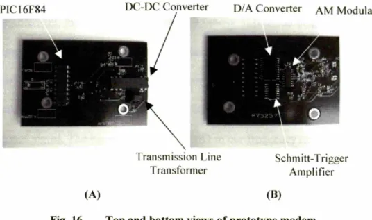
Prototype DC powerlinc communication system with 30 nodes Figure 16 shows the modem used to interface each node with the system.
PIC16F84
(A)
Transmission Line Transformer
D/A Converter AM Modulator
Schmitt-Trigger Amplifier (B)
Fig. 16. Top and bottom views of prototype modem
It consists of a transmission line transformer, a coupling capacitor, a microprocessor (PIC 16F84), a signal modulation chipset, and a DC/DC converter. A DC servomotor equipped with a 12V PWM amplifier was connected to each node. The microprocessor is
-30
-35 muu
Freq [Hz]
Fig. 18. Noise spectrum of operating motor and noise induced by randomly turning the motors on and off
The desired transmission frequency depends not only on the line impedance and noise characteristics described above but also on the required transmission rate and the gain and peak impedance conditions discussed in the previous sections. Sending command information at and above 100 kbps determines the carrier frequency for modulation. Frequency shift keying (FSK) modulation chipsets using carrier frequencies between 3 and 10 MHz meet this requirement. The required amplitude modulation (AM) carrier frequency is on the order of mega-Hertz2. The exact carrier frequency was determined
based on the modem's coupling circuit design.
3.2.2. Selection of Coupling Circuit Component Values
We design the coupling circuitry based on the analysis described in the preViOUS section. In turn, experimental data is recorded and compared to the model to verify the design procedure. In addition to the bandwidth restrictions imposed by the power supply 2Carrier frequency values of AM chip sets have much more variability than their FSK
counterparts. We chose to use AM in order to evaluate the transmission characteristics for a range of carrier frequencies from 2 - 10 MHz.
600 500
---i----t-_.LrtlliI~:I-t---,--!-i-i[r!---,
~----[---i--i--!-!-!i!---i----!---i-1-i-!!
1 00--.m..~----LtU.UU. ..---l---.tLl-1~j-lmm--.~m.J..-i~~.~~:
•••••••••••• ' •••••••••• 1.1 1 111111 : : : : : :::: :::. :::: :::: :: ::: •••••• "" •• I •••••••••••••.
.. . . .
..
".
• . . • . • •.• • • • •••• .•.• • • . o. o •••••••••••••••••••••••• I • , ••••••••••••••• I •••••• • • • • • •••• • • • •••• "' I • "' ••• . . . .... .
.,...
.
.. . .
...
, "'" ...- , , . ",..; ..-
, . 106 Freq[Hz]Fig. 20. Signal transmission impedance viewed from sender for n=1
3000
2500 uum+ --- -+ --+ --~-... +-H H ---or ----+ ---rn1-+-1-~~-1-u _m r n;._u~--1-
+-~-~
+ ~---r_m -rn -;--H -;-r :, , . • • • • • •••• •••• • •••• ••• I •••••••••••••
.
. . ,..
"" "".
...
. . .. . . ., . . . . . ...
: ~ l::::::: :::: : :::: :::: : :::f:
::l]:~ftjw~mItI:IJllli ltj::IlIIJIII::::I::::I:I!Irll
: : : : : : : : : :::: : : : : : :~ : : : : : : : : : :::: : : : : : : : : : : ::: :::: : :::::: : : : : : : ::: :::: : ::: 1 i 1 ill 111 j i j ij j j1 ~) j j i j ijill j j j j ijij50:
mu-l:--t--tHl[tlu---I--turlJ~iu\::tUl-ttt!u-u!uLlJliJl
104 105 106 107 108 Freq [Hz]Fig. 21. Signal transmission impedance viewed from sender for n =30
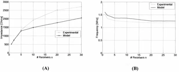
The question may arise as to how well our model predicts the limiting case as n becomes large. To address this issue, it is helpful to look at the model and experimental results as a function of
n.
Specifically we can look at the magnitude of the impedance peak, and the frequency at which it occurs. We showed earlier that the peak magnitude and frequency reach a maximum and minimum value (respectively) well before n reaches infinity. We now try to calculate the error in the predicted and actual steady-state values.Figure 22(A) shows how the peak magnitude varies as a function of n according to the model and experimental results. There is 'final' error of
soon
(20%). For the frequency plot given in Figure 22(B), there is an error of 50 kHz (5%). Thus, while the limiting value of impedance magnitude shows significant error, the frequency at which it occurs can be predicted quite closely_ In our design procedure, this frequency is critical because it is used to help determine the parameter values of Table 1. However, the magnitude is not as important. Thus, the utility of the model is verified once again in terms of its ability to predict the limiting behavior as a function of n.2 --- Experimental - Model 30 25 20 15 # Receivers n i 1_5 \ ..: I. N I I ~ --r---j--- ---j---- --- ----1- __m_
g
1 --- -r---t---j--1
--~ I I i I ~ ! I ! ! ! I I 0.5 --t I !I
II
I I ' I I 1 30 25 10 15 20 #Receivers n 5 (A) (B)Fig. 22. Resonant behavior; peak magnitude and peak frequency as a function of the number of receivers
Fig. 23. Mobility aids for disabled children and elderly persons
The mechanized walker and standing aid shown here both use some standard servo-system design. With the apparatus presented in this work, such machines can be simplified. The central controller and power supply (a battery, in this case) can be kept to a small size. Actuators can then be placed directly at the wheels, leaving the rest of the apparatus aesthetically appealing and easily maneuverable. A simple schematic illustrating this idea is pictured in Figure 24.


