HAL Id: hal-02169322
https://hal.sorbonne-universite.fr/hal-02169322
Submitted on 1 Jul 2019
HAL is a multi-disciplinary open access archive for the deposit and dissemination of sci-entific research documents, whether they are pub-lished or not. The documents may come from teaching and research institutions in France or abroad, or from public or private research centers.
L’archive ouverte pluridisciplinaire HAL, est destinée au dépôt et à la diffusion de documents scientifiques de niveau recherche, publiés ou non, émanant des établissements d’enseignement et de recherche français ou étrangers, des laboratoires publics ou privés.
The dual role of viscosity in capillary rise
Joachim Delannoy, Suzanne Lafon, Yukina Koga, Etienne Reyssat, David
Quéré
To cite this version:
Joachim Delannoy, Suzanne Lafon, Yukina Koga, Etienne Reyssat, David Quéré. The dual role of viscosity in capillary rise. Soft Matter, Royal Society of Chemistry, 2019, 15 (13), pp.2757-2761. �10.1039/C8SM02485E�. �hal-02169322�
The dual role of viscosity in capillary rise
Joachim Delannoy, Suzanne Lafon, Yukina Koga, Étienne Reyssat & David Quéré
Physique & Mécanique des Milieux Hétérogènes, UMR 7636 du CNRS, ESPCI Paris, PSL Research University, Sorbonne Université, Université Paris Diderot, 75005 Paris, France.
The spontaneous rise of a wetting liquid in a capillary tube is classically described by Washburn’s law: the meniscus height increases as the square root of time, a law singular at short time, where the velocity diverges. We focus here on the early dynamics of the rise of viscous liquids, and report an initial regime of constant velocity contrasting with Washburn’s prediction. This is explained by considering the contact line friction at the liquid front, and confirmed by the influence of prewetting films on the tube walls, whose presence is found to speed up the rise and more generally to provide an ideal framework for quantifying the friction at contact lines.
Washburn’s law classically describes the dynamics of wetting liquids inside porous media [1]. It predicts that the position of the liquid front increases as the square root of time, as long as gravity can be neglected. As also discussed by Bell and Cameron [2], and by Lucas [3], this law, first established in the simple geometry of capillary tubes, results from a balance between the driving capillary force and viscous friction along the walls. Denoting the meniscus position and velocity as z and 𝑧, the tube radius as r and the liquid surface tension and viscosity by 𝛾 and 𝜂, these two forces respectively scale as 𝛾r and 𝜂z𝑧, whose balance leads to Washburn’s equation: 𝑧 𝑡 ~ 𝛾𝑟𝑡 𝜂 !/! (1)
In the case of partial wetting (characterized by the contact angle 𝜃0 > 0 made by the liquid on the tube wall), the driving force is weakened by a factor cos𝜃0, which yields a
dynamics slowed down by a factor cos1/2𝜃0, compared to eq. (1). Washburn’s law is famous for many reasons: (1) Beyond the simple case of tubes, it generally describes the impregnation of much more complex media such as paper, fabrics, sand and rough surfaces [4–7]. (2) It allows in principle to deduce a characteristic radius of invasion from impregnation dynamics, or, if the latter quantity is already known, the contact angle inside the porous medium [8–9]. (3) It clearly highlights the efficiency of impregnation at small distance z, as qualitatively observed when a liquid (ink for instance) contacts porous structures (paper for instance).
The dynamics at short time and short scale must be questioned, since eq. (1) predicts an unphysical diverging velocity in this limit. As first discussed by Bosanquet [10], the viscous dynamics is preceded by an inertial regime during which liquid is brought in motion. Neglecting the liquid viscosity and the influence of gravity, the dynamics in this regime results from a balance between inertia (scaling as 𝜌𝑟!𝑧!) and capillary force
(scaling as 𝛾r), which yields a constant meniscus speed c ~ (𝛾/𝜌𝑟)!/! [11], a velocity of
typically 10 cm/s in millimetric tubes. The transition towards the Washburn regime happens when both dynamics cross, that is, after a time 𝜏 ~ 𝜌r2/𝜂 [12]. This time can be reinterpreted as the time necessary for the viscous boundary layer to diffuse across the tube width, and it is easily observable for wide tubes (at least millimetric, or even larger as found in microgravity environment) and for liquids of low viscosity such as water and
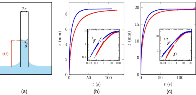
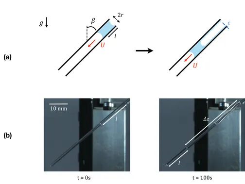
light oils. Conversely, we expect the inertial regime to be almost invisible in very thin tubes and/or for viscous liquids. In a millimetric tube, for instance, with an oil 300 times more viscous than water, the time 𝜏 is 3 ms, and the corresponding spatial extension c𝜏 is only a fraction of a millimeter – making this regime undistinguishable from the establishment of the meniscus at the onset of the rise. However, the beginning of the rise of a viscous wetting liquid in a millimetre-wide tube is far from obeying Washburn’s law. The experiment, sketched in figure 1a, consists in following the meniscus height z (defined between the bath level and the bottom of the rising meniscus) after making a vertical glass tube (inner radius r = 0.5 mm) contact a bath of viscous silicone oil (𝛾 = 21 mN/m, 𝜌 = 980 kg/m3, 𝜂 = 350 mPa.s and 𝜃0 = 0). As seen in figure 1b (red curve), the rise is slow (two minutes are necessary to reach the equilibrium height of 8 mm), but it constantly deviates from Washburn’s law. The beginning of the rise, specifically, is observed to take place at a finite and constant velocity (of ~1.7 mm/s) in contradiction with the prediction of eq. (1). This observation is confirmed by plotting the same data in logarithmic scales (inset in the figure): the first second of the rise indeed obeys a scaling law with exponent 1, as highlighted by a dotted line, confirming the existence of a regime of constant speed at short time. Interestingly, Washburn briefly noted in his original paper that he needed to precoat the tubes with a thin liquid film to get a satisfactory agreement between data and theoretical expectations. Such films can be deposited by moving a slug of oil inside the tube with a well-defined velocity, allowing us to control the film thickness [13] (see the supplementary information). If performing the same capillary rise experiment as previously, yet in a tube precoated by a film of silicone oil with a thickness ε = 24 µm (much smaller than the tube radius r), we observe an impressively enhanced dynamics of the rise at all scales (blue data in figure 1b): after one second, the meniscus is about twice higher than in a dry tube, and the final equilibrium is reached in about 40 s, that is, three times quicker. However, the same data plotted in logarithmic scales reveal that the very beginning of the rise still (yet more briefly) takes place at a constant speed, but this speed is now 7.2 mm/s, larger by a factor ~4 than previously. In both cases, the Washburn regime is not observed, because the linear rise brings the meniscus at a height such that gravity becomes significant, another source of deviation from eq. (1) where it is neglected. This can be circumvented by using a thinner tube, as reported in
figure 1c, where we report the rise of a silicone oil with viscosity 𝜂 = 50 mPa.s in a tube twice thinner (r = 0.23 mm) either dry (red data) or prewet by a film of thickness 𝜀 = 4 µm (blue data). Dynamics remains quicker in the prewet tubes, but the log-log plot displayed in the inset reveals that the regime of constant speed has significantly shrunk in the dry case, and even became invisible in the wet case, so that Washburn’s law (the dashed line with slope 1/2 drawn in the figure) can now be observed. Figure 1. Rise dynamics in vertical tubes invaded by a viscous wetting oil. Tubes are either dry (red data) or prewet (blue data). (a) Sketch of the experiment with a wetting liquid. Blue and white represent liquid and air, respectively. The meniscus at a height z(t) has an apparent contact angle 𝜃. The origin of time is taken when the tube contacts the liquid. (b) The oil viscosity 𝜂 is 350 mPa.s, the tube radius is r = 0.5 mm and the thickness of the prewetting film is 𝜀 = 24 µm. The insert shows the data in logarithmic scales, and both dotted lines have a slope 1. (c) Same experiment with 𝜂 = 50 mPa.s, r = 0.23 mm and 𝜀 = 4 µm. In the logarithmic plot of the insert, the prewet tube now provides a Washburn regime with slope 1/2 (dashed line) while the initial dynamics in the dry tube remains linear (slope 1, dotted line).
Our experiments thus show that dry tubes of millimetre-size diameter are invaded by viscous liquids at a constant velocity V, which corrects the singular character of Washburn’s law at short time, yet without influence of inertia – always negligible at the scale of our experiments. This regime appears more clearly in the case of dry tubes (where it concerns typically the first millimetre of the rise), even if it can also be observed at smaller scales in prewet tubes, which makes us suspect a viscous origin for the effect. This is confirmed in figure 2, where we plot the meniscus velocity V at short time (deduced from plots such as figure 1) as a function of the oil viscosity 𝜂 varied by a (a) (b) (c) 2r θ z(t) 0.01 0.1 1 10 100 0.1 1 10 0 50 100 0 2 4 6 8 t (s) z (m m ) 0.01 0.1 1 10 100 1 10 0 50 100 0 5 10 15 20 t (s) z (m m ) 1 1 1/2
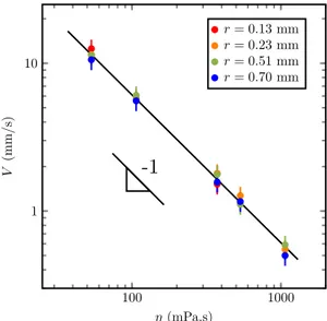
factor 20, between 50 mPa.s and 1000 mPa.s, keeping the surface tension at a constant value 𝛾 = 21.0± 0.2 mN/m. Figure 2. Initial velocity V of a viscous wetting liquid invading a capillary tube as a function of its viscosity 𝜂. The surface tension of the silicone oils used in this experiment is 𝛾 = 21.0 ± 0.2 mN/m and the colours indicate the radius of the tube. The black line is a fit with slope −1. The meniscus velocity V decreases as the oil becomes more viscous, from ~11 mm/s (for 𝜂 = 50 mPa.s) to ~0.5 mm/s (for 𝜂 = 1000 mPa.s). The corresponding Reynolds numbers defined at the scale of the tubes, Re = 𝜌Vr/𝜂, range between 5.10−4 and 10−1, which confirms that inertia can be neglected. Conversely, the logarithmic scales in figure 2 evidence that V decreases as 1/𝜂, confirming that the capillary action is opposed in this regime by a viscous force. Interestingly, data obtained at a given viscosity with tubes of radii varying between 0.13 and 0.70 mm nearly superimpose, which suggests a local viscous dissipation instead of the global one assumed in Washburn’s law (eq. 1). Dissipation indeed also happens close to the moving contact line, at the scale of the meniscus, whose motion is accompanied by a deformation so as to form a dynamic contact angle 𝜃(V), as sketched in figure 1a. Illuminated with white light from below, the meniscus is observed in the time-lapse photograph of figure 3a to rise at constant velocity with a flattened shape whose stationary nature is evidenced by its identical apparent thickness. We subtracted in this image the outside meniscus that may mask the field of interest, and highlighted the tube walls with red lines. At larger scale, that is, later (figure 3b), the meniscus slows down markedly (the constant spacing in the figure -1 100 1000 1 10 ⌘ (mPa.s) V (m m /s ) r = 0.13 mm r = 0.23 mm r = 0.51 mm r = 0.70 mm
is obtained by increasing the time interval between successive images) and it simultaneously thickens, a consequence of the relaxation of the dynamic contact angle θ towards its equilibrium value 𝜃0 = 0. Hence, the meniscus shape in figures 3a and 3b
allows us to distinguish the two successive viscous regimes of invasion.
Figure 3. (a) Time-lapse evolution of a viscous oil (𝜂 = 50 mPa.s) rising in a dry glass tube (r = 0.23 mm).
The picture represents the meniscus at t = 36, 48, 60 and 72 ms (from bottom to top). The outside meniscus was masked for clarity. (b) Time-lapse evolution of a viscous oil (𝜂 = 350 mPa.s) rising in a glass tube (r = 0.7 mm). The picture shows the meniscus at t = 1.4, 4.2, 11 and 92 s (from bottom to top). In figures (a) and (b), the light source, placed under the bath, highlights the curvature, which makes the meniscus appear in white.
In the linear regime, the local balance of forces determines θ, which in turn sets the meniscus velocity V – both found, consistently, to be constant in this regime (figure 3a). Approximating the contact line region by a wedge with (small) apparent angle 𝜃, as sketched in figure 4a, the shear stress scales as 𝜂V/𝜃x, where x is the distance to the wedge tip. Integrating the latter formula with respect to x and along the tube perimeter yields a friction Fw ≈ 𝜂rV/𝜃 ln r/𝜀, where the macroscopic and microscopic cutoff lengths r and 𝜀 in the logarithmic term respectively correspond to the meniscus size and to the
thickness of the film on which the wedge advances [14]. The way the dynamic angle 𝜃 in
Fw depends on V is classically obtained by balancing Fw by the capillary force Fc ≈ 𝛾r (1 −
cos 𝜃) opposing the viscous deformation of the wedge. At small angle 𝜃, this balance yields Cox-Voinov-Tanner law [15–17], that is, 𝜃3 ≈ 𝜂V/𝛾 ln r/𝜀, which makes explicit the viscous friction in the wedge, Fw ≈ r 𝛾1/3(𝜂V ln r/𝜀)2/3, and highlights its non-linear character in velocity. 1 mm (b) (a) -2 mm
-
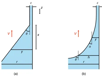
Figure 4. Simplified (a) and more realistic (b) shapes of a wetting meniscus advancing at a speed V in a
tube of radius r. 𝜀 denotes the thickness of the film on which the meniscus progresses, θ is the apparent (dynamic) contact angle and x is the vertical distance from the tip of the wedge.
We have two ways of expressing the macroscopic balance of forces governing the dynamics of the rising column. (1) On the one hand, a consequence of the wedge friction
Fw is to modify the Laplace pressure responsible for the rise, owing to the generation of
a dynamic contact angle 𝜃 at the front, as sketched in figure 1a. The modified Laplace force 𝛾r cos𝜃 can then be balanced by the Poiseuille friction in the column FP ≈ 𝜂z𝑧,
which yields an equation for the rise dynamics. (2) On the other hand, an elementary jump of the stationary meniscus by a quantity dz in figure 4a suppresses a surface area of liquid scaling as rdz, corresponding to a decrease of surface energy 𝛾rdz – hence a driving force scaling as 𝛾r. Conversely, we have to consider two viscous frictions, that in the wedge, Fw, and that in the column, FP ≈ 𝜂z𝑧, and the force balance on the liquid column can be written: γr ≈ Fw + FP. Since the wedge friction is itself balanced by the capillary force Fc ≈ 𝛾r (1 − cos 𝜃), we recover the expression derived in (1).
Assuming that the wedge friction dominates the global Poiseuille friction at short time (Fw >> FP), the balance of forces becomes: 𝛾r ≈ Fw ≈ r 𝛾1/3(𝜂V ln r/𝜀)2/3, which provides the initial meniscus velocity: 𝑉 ≈ 𝛾 𝜂 ln 𝑟/ε (2) ! V " y r (b) # h # V " x y z (a) r
A dominant dissipation in the meniscus leads to a constant velocity of propagation, in agreement with the observations in figures 1, 2 and 3. For an initially dry tube and a wetting liquid, the film is typically a precursor film propagating ahead of the meniscus, hence with a molecular thickness (𝜀 ≈ a ≈ 1 nm) [18]. In such conditions, the coefficient ln r/𝜀 ranges from 12 to 13 as the tube radius varies between 0.13 mm and 0.7 mm and its logarithmic nature makes it quite insensitive to the size chosen for its thickness (in the range of a few Angströms). This term lowers the visco-capillary speed 𝛾/𝜂 in eq. (2) by about one order of magnitude. For a silicone oil with a viscosity 𝜂 = 350 mPa.s, our scaling argument predicts V to be typically 5 mm/s, comparable (yet slightly larger) than reported in figures 1b and 2. Equation (2) also explains why the meniscus will initially move faster in prewet tubes. The prewetting film can be seen as a thick precursor of the meniscus, which lowers the logarithmic factor and thus increases the speed. For a film whose thickness is typically 20 µm, the term ln r/𝜀 is reduced by a factor 4 (compared to ln r/a), which multiplies the speed V by the same amount, in agreement with the observations in figure 1. In any case, the velocity V remains much smaller than the inertial velocity (𝛾/𝜌r)1/2 ≈ 10 cm/s, which
underlines once again the negligible role of inertia in our experiments.
The range of the viscous linear regime, before the Washburn behavior, can finally be discussed. The global Poiseuille force FP ≈ 𝜂z𝑧 is negligible compared to the line friction
Fw ≈ r 𝛾1/3(𝜂V ln r/𝜀)2/3 as long as the travelled distance z is smaller than L ≈ r ln r/𝜀, a length sensitive to the state of the tube (dry or prewet), and typically of millimetric amplitude, as found experimentally (insert in figure 1b). L is roughly proportional to r, which explains why the linear regime is significantly longer in figure 1b than in figure 1c. Moreover, these arguments justify why Washburn did not observe this regime, in experiments where tubes were thin (r = 0.15 mm) and prewet – making the distance L smaller than here by one order of magnitude. More generally, the radius r is micrometric in many experiments reported in the literature (especially those with porous media), which makes the linear viscous regime macroscopically unobservable.
We expect from eq. (2) an initial capillary number Ca = 𝜂V/𝛾 ≈ 1/ ln r/𝜀, ranging between 0.07 and 0.09, about 3 times larger than the value measured in figure 2 (Ca = 0.03). We
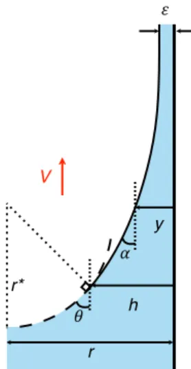
can describe the moving meniscus in a more accurate way (figure 4b). As originally performed by Voinov [16], it is obtained by balancing the capillary pressure with the normal stress exerted by the flow on the free surface. The bending of the interface induces a Laplace pressure in the fluid pc = 𝛾 sin 𝛼 d𝛼/dy where 𝛼(y) is the angle
between the liquid-gas interface and the solid at a distance y from the tube walls (figure 4b). As shown by Moffatt [19], the motion in a liquid wedge induces a pressure on the free surface pf = 2𝜂V/y sin2𝛼/(𝛼 − sin𝛼 cos𝛼) (see also the SI). The balance pc = pf can be integrated between 𝛼 = 0 for y = 𝜀 (at the top of the meniscus) and 𝛼 = 𝜃 for y = h, the local thickness of the dynamical meniscus. We deduce an equation relating 𝜃 and h for a given velocity V: 𝑉 = 𝛾 𝜂 ln ℎ/ε α − sin α cos α 2 sin α dα ! ! (3)
In the limit of small 𝜃, eq. (3) reduces to the classical Cox-Voinov law: 𝜃3 ≈ 9𝜂V/𝛾 ln h/𝜀, an approximation that holds up to 𝜃 < 3𝜋/4 [17]. In the geometry of a tube, we can plug the condition 𝜃(r) = 𝜋/2 in eq. (3), which provides an analytical expression for the velocity V: 𝑉 𝜀 ≈ 𝜋! 72 𝛾 𝜂 ln 𝑟/ε (4)
We recover the scaling expression (2) with a numerical coefficient ∼0.43, so that the capillary number 𝜂V/𝛾 of the initial rise is expected to range between 0.032 (for r = 0.70 mm) and 0.037 (for r = 0.13 mm), as typically observed in figure 2. In these experiments, the tube radius is roughly varied by a factor 5, which, according to eq. (4), only modifies the rising velocity by 15%, – in agreement with the very small variations observed in figure 2 and found to highlight the local character of the dissipation in this regime. Put together, eqs. (3) and (4) yield 𝜃 ≈ 𝜋/2 (lnh/𝜀/lnr/𝜀)1/3, which depicts that 𝜃 quickly approaches 𝜋/2 even at small thicknesses h. For instance, we expect 𝜃 ≈ 0.4𝜋 for h = 1 µm in a dry tube (𝜀 ≈ 1 nm) with radius r = 0.5 mm. Hence we understand the meniscus flatness observed in figure 3a to be a hallmark of the early viscous regime.
We can be more quantitative by looking at the way the meniscus velocity depends on the thickness 𝜀 of the prewetting film, which is expected from eq. (4) to be a logarithmic variation. The thickness 𝜀 can be varied much more broadly than the tube radius, firstly between dry tubes (for which we expect a nanoscopic precursor film 𝜀 ≈ 1 nm) and prewet tubes (𝜀 ≈ 10 µm); secondly, in the wet regime where 𝜀 can be easily tuned by changing the inclination of the tube during precoating: by modifying the advancing speed of the prewetting slug, we could vary the coating film thickness 𝜀 from 1 µm to 24 µm (see the SI). For each thickness 𝜀, we can measure the initial speed V of the rise, which is displayed in figure 5.
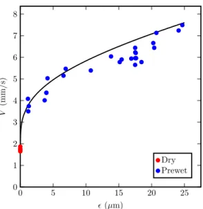
Figure 5. Initial velocity V of a silicone oil (𝜂=350mPa.s, 𝛾=21mN/m) rising in a tube of radius r=0.5
mm as a function of the thickness 𝜀 of the oil film on which the meniscus rises. Dots show the experimental data for dry (red) and prewet (blue) tubes. Equation 3 is drawn with a black line, without any adjustable parameter. We observe two main facts: (1) The meniscus velocity V jumps from 1.7 mm/s for dry tubes (red dots) to 3.7 mm/s for the thinnest coating (𝜀 ≈ 1 µm), in agreement with our model that predicts that the velocity should double when the film thickness increases from 1 nm (precursor film on a dry tube) to 1 µm (prewetting film). (2) The meniscus velocity is a slowly increasing function of the coating thickness that roughly doubles when multiplying the coating thickness by a factor of 25, again in full agreement with expectations: without any adjustable parameter, eq. (3) is observed in figure 5 to nicely describe the slow rise of the velocity V as a function of 𝜀, even if it slightly overestimates 0 5 10 15 20 25 0 1 2 3 4 5 6 7 8 ✏ (µm) V (m m /s ) Dry Prewet
it at large 𝜀. In this limit, as stressed earlier, the range of the viscous linear regime is limited, and the accuracy of the measurements consequently decreases: the transition to the Washburn regime occurs early, which might explain why the observed velocity is found in this limit to be systematically (slightly) below the expectations.
In summary, we showed in this paper that the capillary rise of viscous liquids is first linear in time. We interpreted this observation by considering the friction close to the moving contact line, whose local character explains the existence of an initial, finite speed of rise. This system offers a unique opportunity to test a specificity of the hydrodynamic model of line friction, that is, its celebrated logarithmic divergence (eqs. 2 and 3). By varying the thickness of the film on which the meniscus progresses, we could probe the logarithmic factor of Voinov’s model – a factor treated here not as an
adjustable parameter (as it is most often in the literature) but as a physical quantity whose content can be varied and tested. The agreement between the model and the experiments was found to be quantitative – a valuable information in a field where such direct observations are rare. Acknowledgment We would like to thank Claire Doré and Nicolas Roméo for preliminary experiment, and Hugo Perrin and Christophe Clanet for fruitful discussions. References [1] E.W. Washburn. The dynamics of capillary flow. Phys. Rev., 17, 273–283, 1921. [2] J.M. Bell and F.K. Cameron. The flow of liquids through capillary spaces. J. Phys. Chem., 50, 658–674, 1906.
[3] R. Lucas. Ueber das Zeitgesetz des kapillaren Aufstiegs von Flüssigkeiten. Kolloid-Zeitschrift, 23, 15–22, 1918.
[4] A. Perwuelz, P. Mondon, and C. Caze. Experimental Study of Capillary Flow in Yarns. Text. Res. J., 70, 333–339, 2000.
[5] M. Lago and M. Araujo. Capillary rise in porous media. J. Coll. Int. Sci., 234, 35–43, 2001. [6] A. Marmur. Kinetics of penetration into uniform porous media: Testing the
equivalent-capillary concept. Langmuir, 19, 5956–5959, 2003.
[7] S.F. Nia and K. Jessen. Theoretical Analysis of Capillary Rise in Porous Media. Transp. Porous Media, 110, 141–155, 2015.
[8] A. Marmur and R.D. Cohen. Characterization of porous media by the kinetics of liquid penetration: the vertical capillaries model. J. Colloid Interface Sci., 189, 299–304, 1997. [9] J. Bachmann, S.K. Woche, M.O. Goebel, M.B. Kirkham and R. Horton. Extended methodology
for determining wetting properties of porous media. Water Resour. Res., 39, 1–14, 2003. [10] C.H. Bosanquet. On the flow of liquids into capillary tubes. Philos. Mag., 45, 525–531, 1923.
[11] D. Quéré. Inertial capillarity. Europhys. Lett., 39, 533–538, 1997.
[12] N. Fries and M. Dreyer. The transition from inertial to viscous flow in capillary rise. J. Colloid Interface Sci., 327, 125–128, 2008.
[13] F.P. Bretherton. The motion of long bubbles in tubes. J. Fluid Mech., 10, 166–188, 1961. [14] J.H. Snoeijer and B. Andreotti. Moving contact lines: scales, regimes and dynamical
transitions. Ann. Rev. Fluid Mech. 45, 269–292, 2013.
[15] L.H. Tanner. The spreading of silicone oil drops on horizontal surfaces. J. Phys. D. Appl. Phys. 12, 1473–1484, 1979.
[16] R.G. Cox. The dynamics of the spreading of liquids on a solid surface. Part 1. Viscous flow. J. Fluid Mech., 168, 169–194, 1986.
[17] O.V. Voinov. Hydrodynamics of wetting. Fluid Dyn., 11, 714–721, 1976.
[18] L. Leger and J. F. Joanny. Liquid spreading. Reports Prog. Phys. 55, 431–486, 1992.
[19] H.K. Moffatt. Viscous and resistive eddies near a sharp corner. J. Fluid Mech. 18, 1–18, 1964.
The dual role of viscosity in capillary rise
Joachim Delannoy, Suzanne Lafon, Yukina Koga, Étienne Reyssat & David Quéré
Physique & Mécanique des Milieux Hétérogènes, UMR 7636 du CNRS, ESPCI Paris, PSL Research University, Sorbonne Université, Université Paris Diderot, 75005 Paris, France.
Supplementary Information 1. Derivation of the viscous friction in the meniscus
Here, we briefly recall the derivation by Moffatt of the pressure exerted by a viscous fluid moving in a corner, a situation sketched in figure SI1 [18].
Figure SI1. Sketch of a liquid wedge (blue) with apparent angle 𝛼 moving on a solid surface (black line) at
a velocity V, in the reference frame of the wedge. ur and u𝜃 are the fluid velocity in the coordinates (r, 𝜃).
Denoting the wedge angle as 𝛼 and its speed as V, the flow is described in the reference frame of the moving wedge by a stream function 𝜓, that verifies ur = 1/r(∂𝜓/∂𝜃), and u𝜃 = -∂𝜓/∂r, where ur and u𝜃 are the radial and tangential velocities in coordinates (r, 𝜃). For a viscous flow, 𝜓 is a solution of the Stokes equation, ∇4𝜓 = 0, whose solutions can be decomposed as 𝜓 = V r𝜆f(𝜃). Close to the tip of the wedge, the solutions must verify 𝜆 = 1 to obtain a non-trivial, finite velocity for r→0. The boundary conditions are ur = V and u𝜃 = 0 at the liquid-solid interface, and u𝜃 = 0 and a shear stress 𝜎𝜃r = 0 at the
V
!
"
r u"
liquid-gas interface, which implies f’(0) = 1, f(0) = 0, f(𝛼) = 0 and f’’(𝛼) − f(𝛼) = 0. Solving the Stokes equation with these boundaries conditions for 𝜓 = V rf(𝜃) yields:
𝜓 = 𝑟𝑉𝛼 sin 𝜃 − 𝜃 sin 𝛼 cos 𝜃 − α
𝛼 − sin 𝛼 cos 𝛼 ≡ 𝑟𝑉. 𝑔! 𝜃 (SI.1)
where we introduced the function g𝛼 for clarity. The pressure gradient obeys ∇p = 𝜂∆u, and its projection along the radial coordinate is: !" !"= 𝜂 !!!! !!! + ! !! !!!! !!! + ! ! !!! !" − ! !! !!! !! − !! !! = !" !![𝑔! ! 𝜃 + 𝑔 !! 𝜃 ] (SI.2) Integrating along r at the liquid-air boundary (𝜃 = 𝛼) gives the pressure induced by the fluid motion on the moving interface: 𝑝 ! 𝛼 = −!"! 𝑔!! 𝛼 + 𝑔!! 𝛼 =!!!! !"# !! !!!"# ! !"# ! (SI.3) where y = r/sin 𝛼 represents the local thickness of liquid as defined in figure 4b. 2. Prewetting the tubes In order to prewet the tube walls, we place a slug of oil with centimetric length l and tilt the tube by an angle 𝛽 with respect tothe vertical. The slug reaches a steady state as its weight ~𝜌r2lg cos 𝛽 is balanced by the viscous friction ~𝜂lU, where U is the slug velocity that can be controlled by the inclination of the tube (figure SI.2 (a)). For each experiment with prewet tubes, we measure the velocity U by timing the descent in tubes of known length. The thickness 𝜀 of the deposited film is then calculated using Bretherton’s formula 𝜀 = 1.34 r (𝜂U/𝛾)2/3 [13]. As seen in figure SI.2 (b), 𝜀 can also by deduced from the shortening ∆l of the liquid slug along its descent. In this case, we measure 𝜀 = r ∆l/2U∆t = 21 µm, in good agreement with the value expected using Bretherton’s formula, that is, 22 µm. When the drop reaches the end of the tube, we
remove it gently by absorbing the oil with a paper, and then perform the experiment presented in figure 1with the other side of the tube.
Figure SI2. (a) Sketch of an oil slug (in blue) of initial length l advancing at a constant speed U in a tube of radius r inclined by an angle 𝛽 to the vertical. As it moves, the slug deposits a liquid film of thickness 𝜀 on the tube walls. (b) Pictures of a drop advancing in a tube with r = 0.5 mm and 𝛽 = 50°. In the left picture, the drop length is l = 16.7 mm. In the right picture, that is, ∆t =100s later, the drop has progressed by ∆z = 37 mm, at velocity U = 0.37 mm/s, and its length has become l = 13.5 mm. The thickness of the deposited film deduced from the slug shortening is 21 µm. 3. Meniscus shape and macroscopic contact angle
Eq. 3 is an implicit equation between h and 𝜃 = dh/dx that we can integrate using a numerical solver (such as ode15i with MATLAB). The shape of the meniscus depends on its velocity, whose initial value is given by eq. 4: V ≈ 𝛾𝜋3/(72lnr/𝜀). Later, the meniscus speed 𝑧 decreases during the rise because of bulk viscous dissipation and gravity. We sketch the meniscus in figure SI3, where we highlight the coexistence of dynamic and static parts drawn with solid and dashed lines, respectively.
g l ! " U r = 0.51 mm, U = 375 mm/s, w = 17um, l = 1.9 cm U (a) (b) 2r 10 mm t = 0s t = 100s l l ∆z
Figure SI3. Sketch of the matching between the static and dynamical part of the meniscus. On the left part
of the sketch, the static meniscus is a portion of sphere with radius of curvature r* while the dynamic meniscus is described in SI1. The matching between the two menisci is done for y = h and 𝛼 = 𝜃, when the two curvatures balance.
The size h of the dynamical meniscus can be obtained from the matching of the curvatures between the part influenced by the flow and the static part of the meniscus (with a spherical shape of radius r*). The curvature induced by the flow in the dynamical part is 2Casin2(𝛼)/y(𝛼 − cos 𝛼 sin𝛼) (see SI1) and it is 1/r* = cos𝜃/(r − h) in the static part of the meniscus, which yields:
ℎ = 2 𝐶𝑎 𝑟 − ℎ !"# ! !"# !
!!!"# ! !"# ! (SI.4)
Using eq. (3), we obtain an implicit equation between h and 𝜃 for a meniscus advancing on a film of thickness 𝜀 in a tube of radius r.
ℎ !" ! ! !!!= !"# ! !"# ! !!!"# ! !"# ! !!!"# ! !"# ! ! !"# ! dα ! ! (SI.5)
Combined with eq. SI4, we obtain a relation between the angle 𝜃 and the thickness of the dynamical meniscus h with the velocity of the meniscus (figure SI4).
! " y r V # h r*
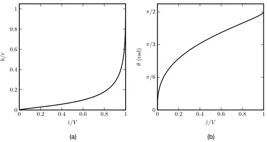
Figure SI4. (a) Thickness of the dynamical meniscus divided by the tube radius and (b) macroscopic
contact angle as a function of the meniscus velocity v divided by the initial velocity V obtained from eq. (4) for a meniscus advancing on film of liquid of thickness 𝜀 = 1nm.
The size of the dynamical meniscus h approaches r as the meniscus velocity 𝑧 is close to the initial velocity V (defined by eq. 4). As the meniscus slows down, the size h of the dynamical region rapidly becomes small whereas the angle 𝜃 is still rather large. For instance in a tube of radius 0.7 mm, when the velocity has decreased by a factor 2, the thickness of the dynamic meniscus is h ≈ 100 µm and the contact angle 𝜃 is above 𝜋/3 a consequence is that 𝜃 appears as a macroscopic contact angle, that depends on the meniscus velocity. We recover in figure SI5.a the shape of the dynamic meniscus with eq. 3 (y < h(𝑧), solid line), and the static part of curvature r* = [r − h(𝑧)]/cos𝜃(𝑧) (y > h(𝑧), dashed line).
We can also retrieve the global behavior of the rising liquid column: the meniscus is driven by a force 2𝜋𝛾r cos𝜃(𝑧) and slowed down by viscous friction in the bulk (8𝜋𝜂z𝑧)
and gravity (𝜋r2𝜌gz) which yields the differential equation SI.6:
2𝑟𝛾 cos 𝜃(𝑧) = 8𝜂𝑧𝑧 + 𝑟!𝜌𝑔𝑧 (SI.6)
We integrate equation SI.6 to recover the evolution of the meniscus height and compare the numerical integration to the data in figures SI5.b and SI5.c.
(a) (b) 0 0.2 0.4 0.6 0.8 1 0 0.2 0.4 0.6 0.8 1 ˙z/V h /r 0 0.2 0.4 0.6 0.8 1 0 ⇡/6 ⇡/3 ⇡/2 ˙z/V ✓ (r ad )
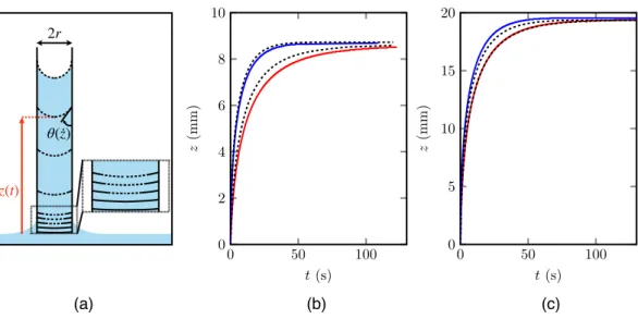
Figure SI5. (a) Meniscus shape at different steps of the rise of a viscous oil (𝜂 = 350 mPa.s) in a dry tube
(𝜀 = 1 nm) with radius r = 0.7 mm (from bottom to top, t = 0, 0.1, 0.2, 0.3, 0.4, 1.2, 3.5, 9.5, 75.5, 150 s, corresponding to a ratio 𝑧/V = 1, 0.96, 0.89, 0.76, 0.51, 0.24, 0.09, 0). The solid and dashed lines respectively represent the meniscus part influenced by line friction and the static region (portion of a sphere). In (b) and (c), we compare the data from figures 1.b and 1.c (coloured lines) and the corresponding numerical integration (dashed black lines) of equation SI.6. (b) Silicone oil of viscosity 𝜂 = 350 mPa.s rising in capillary tube of radius r = 0.5 mm either dry (𝜀 = 1 nm) or prewet (𝜀 = 24 µm).
(c) Silicone oil of viscosity 𝜂 = 50 mPa.s rising in capillary tube of radius r = 0.23 mm either dry (𝜀 = 1 nm)
or prewet (𝜀 = 4 µm).
As seen in the figure SI5, the numerical integration (black dashed lines) gives accurate results for both dry (red) and prewet (blue) tubes, without any adjustable parameter. The small difference obtained between the numerical and experimental results could reflect small imperfections of the preweting or precursor film thickness. (a) (b) (c) 2r θ(·z) z(t) 0 50 100 0 2 4 6 8 10 t (s) z (m m ) 0 50 100 0 5 10 15 20 t (s) z (m m ) 0.5 0 0.5 1 0.5 0 0.5 1 y (mm) x (m m ) 0.5 0 0.5 1 0.5 0 0.5 1 y(m m) x (m m ) 0.5 0 0.5 1 0 1 2 3 4 5 6 7 8 y(m m) x (m m ) 0.5 0 0.5 1 0 1 2 3 4 5 6 7 8 y (mm) x (m m ) 0.5 0 0.5 1 0.5 0 0.5 1 y (mm) x (m m ) 0.5 0 0.5 1 0.5 0 0.5 1 y(m m) x (m m )