HAL Id: hal-02470251
https://hal-amu.archives-ouvertes.fr/hal-02470251
Submitted on 17 Apr 2020
HAL is a multi-disciplinary open access archive for the deposit and dissemination of sci-entific research documents, whether they are pub-lished or not. The documents may come from teaching and research institutions in France or abroad, or from public or private research centers.
L’archive ouverte pluridisciplinaire HAL, est destinée au dépôt et à la diffusion de documents scientifiques de niveau recherche, publiés ou non, émanant des établissements d’enseignement et de recherche français ou étrangers, des laboratoires publics ou privés.
Distributed under a Creative Commons Attribution| 4.0 International License
microstructured fibers
Maciej Napiorkowski, Gilles Renversez, Waclaw Urbanczyk
To cite this version:
Maciej Napiorkowski, Gilles Renversez, Waclaw Urbanczyk. Effect of cladding geometry on resonant coupling between fundamental and cladding modes in twisted microstructured fibers. Optics Express, Optical Society of America - OSA Publishing, 2019, 27 (4), pp.5447. �10.1364/OE.27.005447�. �hal-02470251�
Effect of cladding geometry on resonant
coupling between fundamental and cladding
modes in twisted microstructured fibers
M
ACIEJN
APIORKOWSKI,
1,*G
ILLESR
ENVERSEZ,
2ANDW
ACLAWU
RBANCZYK11Department of Optics and Photonics, Wroclaw University of Science and Technology, 50-370 Wroclaw, Wybrzeze Wyspianskiego 27, Poland
2Aix–Marseille Univ, CNRS, Centrale Marseille, Institut Fresnel, UMR 7249, 13013 Marseille, France
Abstract: We analyzed for the first time the effect of variations in the number of air hole rings and the filling factor of twisted microstructured optical fibers on the resonant couplings between fundamental and cladding modes. Rigorous numerical simulations show that these parameters can be used to control the spectral width of the resonance peaks, resonance loss, and relative strength of polarization effects. Furthermore, the number of air hole rings has a decisive impact on the number of twist-induced resonances and their wavelength range.
© 2019 Optical Society of America under the terms of the OSA Open Access Publishing Agreement
1. Introduction
Helical twist provides an additional degree of freedom in shaping propagation characteristics of conventional and microstructured optical fibers and gives rise to new wave phenomena. In the first twisted conventional fibers fabricated by preform spinning during the drawing process, the existence of circular birefringence and single mode guidance even for large normalized frequency was demonstrated [1]. More recently, in the conventional fibers twisted locally with the helix pitch of the order of hundreds or tens of micrometers, the effect of coupling between core and cladding modes was observed and further studied for applications in novel fiber-based devices like sensors, circular polarizers, couplers [2,3], optical vortex generators [4,5], fiber lasers [6,7] and for enhancement of optical activity [8,9].
In general, properties of twisted conventional fibers are determined by their structural parameters and helix pitch. It is known that propagation and sensing characteristics in microstructured optical fibers (MOFs) can be engineered more freely than in conventional fibers. For example, properly designed non-twisted microstructured fibers show unique features like endlessly single mode propagation [10] or hollow core guidance [11]. Furthermore, optimization of microstructure geometry allows for a precise control of chromatic dispersion important for nonlinear applications [12,13], obtaining increased birefringence [14], extreme polarimetric sensitivity to hydrostatic pressure [15] or broad-band single polarization guidance [16]. It is therefore understood that twisted microstructured fibers have attracted recently much attention, as the helical twist allows for an additional control of their propagation and sensing characteristics. It was already shown that the circular birefringence can be induced in twisted MOFs [17,18] and maximized by choosing a proper filling factor of air holes [19]. Twisted MOFs have been also studied for sensors [19,20], polarizers [21,22], vortex guidance [23] and coreless propagation [24].
The effect of resonant coupling between core and cladding modes in twisted MOFs, utilized in most of the proposed applications, has been first reported in [25] and properly explained in [26]. Moreover, the scaling rules which relate the resonant coupling conditions to dimensionless ratios between the wavelength, the lattice pitch and the helix pitch of the twisted MOFs have been investigated in [21]. The obtained results show that for appropriately
#351904 https://doi.org/10.1364/OE.27.005447
designed twisted MOFs, distinct, high loss resonance peaks can be obtained in a broad wavelength range already for the fiber with the millimeter helix pitch, thus allowing for fabrication of coupling based devices using a less demanding preform spinning method. Moreover, the effect of air hole diameter on resonant couplings between core and cladding modes was partially analyzed using the beam propagation method [27].
Nonetheless, the influence of all microstructure parameters on twist-induced resonant couplings in MOFs has not been yet fully explained. In this paper we analyze the effect of the number of air hole rings and the filling factor on the position and strength of the resonance loss peaks in twisted MOFs. The obtained results show that the number of air hole rings, which in non-twisted MOFs influences primarily the mode confinement and loss, has a decisive impact on the number of twist-induced resonant couplings, wavelength range in which the resonances arise, spectral width of resonance peaks and their polarization features. The results presented in this paper, together with the ones reported in [21,26], are sufficient to fully understand the role of all geometrical parameters of the hexagonal microstructure on the resonance loss spectrum in twisted MOFs.
2. Fiber structure and simulation method
The numerical simulations were performed for twisted MOFs with a cross-section shown in Fig. 1. The analyzed fiber is characterized by the fixed value of the lattice pitch ΛL = 3µm and
the right-handed helix pitch ΛH = 500µm. As shown in [21], the chosen values of ΛL and ΛH
allow for observation of many strong resonance peaks in the visible and near infrared wavelength range, including the polarization dependent peaks. In the first part of the simulations, the filling factor d/ΛL = 0.4 was used to be near the critical ratio for endlessly
single mode propagation in the core in non-twisted fibers [28], while the number of the air hole rings NR was changed from NR = 1 to NR = 9. In the second part of the simulations, the
filling factor was changed from d/ΛL = 0.35 to d/ΛL = 0.5 and NR was fixed (we show the
results obtained for NR = 3 and 4). In case of NR = 4 and d/ΛL = 0.4, the analyzed fiber is
identical to the one described in [21], for which the effect of changing ΛL and ΛH was
analyzed in detail.
Spectral dependence of the refractive index of silica glass was determined using the following Sellmeier equation [29]:
Fig. 1. Cross-section of the analyzed twisted microstructured optical fiber. Arrow shows the twist direction.
( )
3 2 22 1 1 i , M i i A n Z λ λ λ = = + −
(1)where wavelength λ is given in microns, while A1 = 0.6961663, A2 = 0.4079426, A3 =
0.8974794, Z1 = 0.0684043, Z2 = 0.1162414 and Z3 = 9.896161.
The propagation characteristics of the twisted MOFs were obtained by using the finite element method combined with the transformation optics formalism [30,31] implemented in COMSOL Multiphysics software. Twisted perfectly matching layers (PML) [31,32] were placed outside of the air holes at a distance of (NR + 0.5)ΛL from the fiber center to estimate
propagation loss. Changing the distance of the PML beyond this value has little influence on the loss of the fundamental mode. Solution convergence was verified by a mesh refinement study.
3. Results
We have calculated the loss spectra of the circularly polarized HE1,1+ (orbital angular momentum L = 0, spin σ = + 1, total angular momentum J = L + σ = + 1) and HE1,1− (L = 0, σ = −1, J = −1) fundamental modes in twisted MOFs to analyze the influence of the number of air hole rings NR and the filling factor d/ΛL on the resonant coupling between the core and
cladding modes.
3.1 Effect of increasing number of air hole rings
In the first step, we analyzed the loss spectra of the HE1,1+ and HE1,1− fundamental modes in the twisted MOFs characterized by ΛL = 3µm, ΛH = 500µm, d/ΛL = 0.4 and NR changing from
1 to 9 in the wavelength range from λ = 400 nm to λ = 1600 nm. We show that addition of successive air hole rings in the microstructured cladding has a strong influence on the number of observed resonance peaks as well as their loss and spectral width.
Fig. 2. Waveguide loss calculated versus wavelength for HE1,1− (blue dotted) and HE1,1+ (red
solid) fundamental modes in twisted MOF with ΛL = 3 µm, ΛH = 500µm, d/ΛL = 0.4 and NR =
1 or NR = 2. Dashed curve shows the loss of the fundamental modes in non-twisted fiber.
Distribution of the axial component of the Poynting vector (Sz) and azimuthal component of
electric field amplitude (Eθ) are also shown for the cladding modes coupling with the HE1,1−
fundamental mode at successive resonances in twisted MOF with NR = 2. Angular symmetry
order of Eθ determines a total angular momentum carried by dominating angular harmonic
denoted as JD.
Small number of air hole rings in the twisted MOF yields simple resonance spectra. In Fig. 2 we show the loss spectra of the fundamental modes in twisted and non-twisted MOFs
fundamental mode and one of the cladding modes, which satisfy the phase matching and the symmetry conditions discussed in details in [26]. The loss peaks observed in the transmission spectrum of the fundamental modes are irreversible as they are caused by leakage of the cladding modes. Distribution of the axial component of Poynting vector (Sz) and azimuthal
component of the electric field amplitude (Eθ) of the cladding modes coupling to the HE1,1− fundamental mode at successive resonances are also shown in Fig. 2.
The loss obtained for NR = 1 in the analyzed wavelength range exceeds 1000 dB/m even in
the non-twisted fiber and is too high for the majority of applications. The loss is additionally enhanced by a twist, especially in the short wavelength range. Furthermore, for NR = 1 there
are no cladding modes confined in the microstructure, which could be phase matched to the fundamental modes in the considered wavelength range.
In fiber with NR = 2, the confinement of the fundamental mode is much better, which leads
to reduction of loss in the non-twisted fiber by orders of magnitude. In the twisted fiber, we observe two resonance peaks related to the coupling to two similar ring-type cladding modes located between the first and second air hole ring (denoted as a and b in Fig. 2). The resonant couplings arise in the short wavelength range and are responsible for gradual formation of the short wavelength loss edge in twisted MOFs [21]. It is worth to mention that similar effect (i.e. resonant coupling with cladding modes) is responsible for creation of the short wavelength loss edge in bent microstructured fibers [33]. The peak (a) obtained for both fundamental modes at λ = 460 nm is characterized by very high losses, while the peak (b) is
much smaller and arises only for the HE1,1− fundamental mode. The two peaks differ
significantly because they are related to coupling with two different types of cladding modes. As shown in [26], the cladding modes in twisted MOFs with 6-fold symmetry are composed of many angular harmonics, each carrying well-defined spin σ = ± 1 and a total angular momentum J = 6k + σ (where k is an integer number), which is directly related to the angular symmetry order of the azimuthal component of electric field amplitude (Eθ). As shown in Fig.
2, the cladding modes responsible for the resonance peaks (a) and (b) in the loss spectra of the HE1,1− fundamental mode (σ = −1) are dominated by the angular harmonic carrying JD = 6−1
= 5. High loss resonance peaks observed for both polarizations are related to coupling with the cladding modes composed primarily of harmonics with the same polarization handedness as the fundamental mode (σ = σfund). Resonance peaks characterized by lower loss, which can
be observed in loss spectra of only one of the fundamental modes (usually HE1,1−) are related to coupling with the cladding modes composed primarily of harmonics with the opposite polarization handedness than the fundamental mode (σ = −σfund).
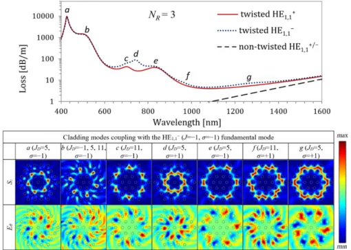
In Fig. 3 we present the loss spectra of the fundamental mode in twisted and non-twisted MOFs with an additional air hole ring (NR = 3). We also show the field distributions for all
the modes responsible for couplings visible in the analyzed wavelength range and identify their dominant harmonics (one or more). As can be seen in Fig. 3, in the microstructure with three rings of air holes (NR = 3) there are couplings to the cladding modes of intensity profiles
and symmetries similar to those observed for NR = 2 (a and b in Fig. 2 are similar to a and d
in Fig. 3) and to more complex cladding modes, which cannot be guided in the structure with less than 3 air hole rings. For NR = 3 most of the observed modes can still be treated as
ring-type modes. The ring-ring-type modes for which a radius can be well defined are located between 2nd and 3rd air hole ring (c, e, f and g in Fig. 3). For such modes the azimuthal component of the electric field amplitude (Eθ) is dominated by a single angular harmonic of order JD.
However, in case of the modes located mainly between 1st and 2nd air hole rings (a and d in Fig. 3), we observe additional local maxima of intensity arising further from the core, which are created by the leaking amplitude from similar modes shown in Fig. 2 reflected back to the microstructure by the third air hole ring. Those additional maxima introduce higher-order harmonics of significant amplitude in the distribution of azimuthal component of the electric field amplitude (Eθ) carrying higher total angular momenta. As a result, it is not possible to
identify the dominant harmonic in case of the mode (b), which has the complex amplitude distribution containing strong harmonics corresponding to J = −1, 5, 11.
Fig. 3. Waveguide loss calculated versus wavelength for the HE1,1− (blue dotted) and HE1,1+
(red solid) fundamental modes in twisted MOF with ΛL = 3 µm, ΛH = 500µm, d/ΛL = 0.4 and
NR = 3. Dashed curve shows the loss of the fundamental modes in non-twisted fiber.
Distribution of the axial component of the Poynting vector (Sz) and azimuthal component of
electric field amplitude (Eθ) are also shown for the cladding modes coupling with the HE1,1−
fundamental mode at successive resonances. Angular symmetry order of Eθ determines the
total angular momentum carried by dominating angular harmonics denoted as JD. For the
cladding mode responsible for the resonant peak b there is no dominant harmonic as the three harmonics with JD = −1, 5, 11 are almost equally visible.
From the results presented in Fig. 3 one can draw additional conclusions concerning the spectral position and loss of the resonance peaks. The resonance peak positions corresponding to ring-type cladding modes can be related to their radius ρ, dominating symmetry order JD
and polarization handedness σ. In case of pairs of the cladding modes with similar JD and σ
([a, e] and [d, g] in Fig. 3), the mode with greater ρ couples with the fundamental mode at longer wavelength, which results in the appearance of the resonance peaks in broader wavelength range for MOFs with greater NR. Furthermore, for pairs of the cladding modes
with similar ρ and JD ([a, d], [c, f] and [e, g] in Fig. 3), the mode with σ = + 1 couples with
the fundamental mode at longer wavelength than the mode with σ = −1. These two effects
lead to significant polarization dependent loss clearly visible in Fig. 3 for a broad wavelength range. The loss related to couplings with the ring-type cladding modes is much smaller for the modes with greater radius because of a lower overlap coefficient with the core modes. Therefore, the loss related to the coupling between HE1,1− fundamental mode (σfund = −1) and
the cladding mode (d) with σ = −σfund and small radius is much higher than the loss related to
the coupling to the modes (c) or (e), for which σ = σfund but the radius is larger. Finally, for
pairs of the cladding modes with similar ρ and σ ([c, e] and [f, g] in Fig. 3), the mode with lower JD couples with the fundamental mode at longer wavelength.
The relations identified in the previous paragraph can be explained using one of the conditions necessary for resonant coupling, which is the phase matching between the fundamental mode (f) and cladding mode (cl) in helicoidal coordinates:
' ' ,
res n f ncl
λ λ= = (2)
where λres is the resonance wavelength and n′f/cl are the effective refractive indices in
helicoidal coordinates, which differ from the effective refractive indices in Cartesian coordinates nf/cl by the term related to the total angular momentum J of the mode and the helix
pitch ΛH, as shown in [5]: / / / 1 'f cl f cl f cl . H n =n + J λ Λ (3)
Furthermore, according to [21], the difference n′f − n′cl can be approximated in a short
wavelength range by:
(
)
(
)
2 ' ' L , f cl cl f cl f L L H n −n Λλ q −q −Λλ J −J ΛΛ (4)where qi is a constant which governs dispersion of a given mode in the short
wavelength range and depends on mode order, fiber geometry and material refractive index [34]. Because in the analyzed case qcl>qf then for every λ below the resonance
wavelength λres, which can be obtained from Eq. (4) for for n’f − n’cl = 0, the effective
refractive index in helicoidal coordinates is higher for the cladding mode than for the fundamental mode:
' ' .
res cl f
n n
λ λ<∀ > (5)
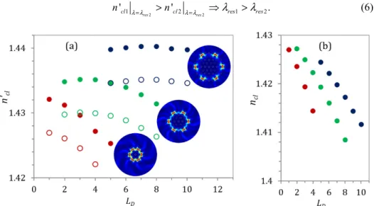
Therefore, by combining Eqs. (2) and (5), one can show that if the effective refractive index in helicoidal coordinates is higher for the cladding mode (1) than for the cladding mode (2) at the wavelength for which there is resonant coupling with the cladding mode (2), then the resonant coupling of the fundamental mode with the cladding mode (1) occurs for greater wavelength: 2 2 1 2 1 2 ' ' . res res cl cl res res n λ λ= >n λ λ= λ >λ (6)
Fig. 4. Effective refractive index in helicoidal coordinates n′cl (a) and in Cartesian coordinates
ncl (b) calculated for λ = 1280 nm versus dominating orbital angular momentum LD = JD−σ for
selected ring-type modes in MOFs with NR = 2 (red), 3 (green) and 4 (blue). In (a) full dots
correspond to modes with σ = + 1 while empty dots to modes with σ = −1. Distributions of axial component of the Poynting vector (Sz) for ring-type cladding modes in MOFs with
Using the above relation, it is possible to determine the sequence of resonant couplings by analyzing the values of n′cl. In Fig. 4(a) we show the numerically obtained values of n′cl for
ring shaped modes located between the last and the second-last air hole rings in MOFs with NR = 2, 3 and 4, which have intensity profiles similar to modes (b in Fig. 2, g in Fig. 3 and k
in Fig. 5) at λ = 1280 nm (spectral position of peak k in Fig. 5). In Fig. 4(b) we present the approximated values of effective indices of the cladding modes in Cartesian coordinates (ncl)
obtained by replacing in Eq. (3) the total angular momentum of the cladding modes Jcl by the
momentum JD carried by dominating angular harmonics.
Numerically obtained relations between n′cl and dominating orbital angular momentum LD
= JD−σ cannot be accurately described using analytical formulas derived for the modes guided
in similar but simpler structures, like thin cylindrical layers [35] or cylindrical arrays of weakly coupling waveguides [36,37]. However, similarly as in case of annular modes guided in thin cylindrical layers, the effective index of the cladding modes in microstructured fiber ncl decreases for greater L and increases for greater ρ, regardless of λ. These relations are
sufficient to explain the sequence of resonance peaks observed in Fig. 3.
For modes characterized by the same JD and σ, the mode located further from the fiber
axis has greater n′cl for any λ and therefore is phase matched to the fundamental mode at
longer wavelength. Similarly, for pairs of the cladding modes with the same ρ and JD, the
effective index n′cl of the mode with σ = + 1 and LD = JD−1 is always greater than n′cl of the
mode with σ = −1 and LD = JD + 1. It should be emphasized that these rules are valid for ring
shaped modes guided in MOFs with any number of hole rings NR and moderate twist rates,
which do not spoil the dispersion relations depicted in Fig. 4. As shown in [21] high twist rate increases leakage and changes dispersion relations of the cladding modes, especially those surrounded by small number of air hole rings, which can alter the order of appearance of selected loss peaks in transmission spectrum of the fundamental modes.
One can also see that for the MOFs with NR = 2,3 and 4, which were considered in detail,
the ring-type cladding modes of similar radius and polarization handedness have longer resonance wavelength for smaller J. However, this is not a universal rule because the value of LD = JD−σ for which n’cl of ring-type mode reaches maximum increases with NR as can be
seen in Fig. 4(a).
In Fig. 5. we show the loss spectra of the fundamental mode and field distributions of all cladding modes responsible for couplings in the analyzed wavelength range in the twisted MOFs with 4 air hole rings (NR = 4). This fiber structure is identical as the one analyzed in
[21] for which the effect of changing ΛL and ΛH was analyzed in detail. For twisted MOFs
with NR≥4, in addition to ring-type modes, there are couplings with the cladding modes
spanning over several air hole rings and covering a large part of the microstructure, for which single dominating harmonic cannot be identified (b, c, d and e in Fig. 5). Once again the modes for which the radius and symmetry order can be identified without any ambiguity are located between the last and the second-last air hole rings (k in Fig. 5). For modes which are ring-type in the MOFs with NR = 3, additional radial and azimuthal oscillations appear in the
Eθ distributions for their counterparts propagating in the MOF with NR = 4 (a, f, g, h, i, j in
Fig. 5 are similar to a, d, c, e, f, g in Fig. 3). Even if in case of such complex modes the dominating harmonic can still be identified, its contribution to the overall amplitude distribution is noticeably reduced.
Adding a fourth air hole ring significantly reduces non-resonant loss in a non-twisted MOF and consequently improves visibility of the polarization dependent peaks, which is strongly reduced by the long wavelength loss edge in the MOF with NR = 3 (i, j in Fig. 5 and
f, g in Fig. 3). On the other hand, the non-resonant loss in the MOF with NR = 4 is still high
enough to completely suppress the low loss polarization dependent resonance peaks related to
the coupling between HE1,1− fundamental mode and most of the cladding modes located
between 3rd and 4th air hole rings, which in the analyzed case are phase matched for λ>1700 nm. Similar suppression effect was previously observed and discussed in [21].
Fig. 5. Waveguide loss calculated versus wavelength for HE1,1− (dotted) and HE1,1+ (solid)
fundamental modes in twisted MOF with ΛL = 3 µm, ΛH = 500µm, d/ΛL = 0.4 and NR = 4.
Dashed curve shows the loss of the fundamental modes in non-twisted fiber. Distribution of the axial component of the Poynting vector (Sz) and azimuthal component of electric field
amplitude (Eθ) are also shown for the cladding modes coupling with the HE1,1− fundamental
mode at successive resonances. Angular symmetry order of Eθ determines total angular
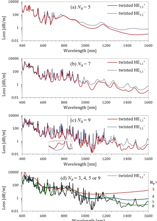
Fig. 6. Waveguide loss calculated versus wavelength for HE1,1− (dotted) and HE1,1+ (solid)
fundamental modes in twisted MOF with ΛL = 3 µm, ΛH = 500µm, d/ΛL = 0.4 and NR = 5 (a),
NR = 7 (b) and NR = 9 (c). Dashed curve in (a) shows loss of the fundamental modes in
non-twisted fiber. For Nr>5 the loss was too small to be precisely determined. Inset in (c) shows
one of the polarization dependent loss peaks observed only for HE1,1+ fundamental mode. In
(d) we compare the loss calculated for HE1,1+ fundamental modes in twisted MOFs with
In Figs. 6(a)-6(c) we show the simulation results for selected MOFs with NR>4. For such
fibers there are much more resonance peaks associated to both the ring-type and the extended cladding modes, which arise in larger microstructured cladding. As it can be seen in Fig. 6, increasing NR above 4 leads to effects similar to those observed for lower NR. Non-resonant
loss is reduced and more couplings are observed. Additional resonance peaks appear in the whole analyzed wavelength range but are easiest to identify for longer wavelengths because for shorter wavelengths they are close to much larger peaks existing already in more limited microstructure. In some cases, these emerging resonances disrupt broad ranges of polarization dependent loss bands observed for the MOFs with small NR. In Fig. 6(d), it can also be seen
that the resonance peaks are getting higher and spectrally narrower with increasing NR (e.g.
the peaks around λ = 550 nm and λ = 700 nm). This effect is related to improved confinement of the cladding modes and the reduced loss mismatch between coupling modes, which for low NR can lead to incomplete coupling characterized by broad, low loss peaks [38]. Additionally,
improved confinement of the cladding modes observed for increasing NR gradually stabilizes
their field profiles as well as effective refractive indices and consequently the spectral positions of the resonance peaks.
Finally, for large NR we observe another type of polarization dependent loss peaks.
Typically, as it can be seen in Fig. 3 and Fig. 5, respectively for NR = 3 and NR = 4, higher
loss in the polarization dependent couplings occurs for the HE1,1− fundamental mode. For NR
greater than 5, another type of polarization dependent loss peaks begins to appear, which is characterized by greater loss of the HE1,1+ fundamental mode. One of such peaks is shown in the inset to Fig. 6(c) for NR = 9. Peaks of this kind are related to coupling between the HE1,1+ fundamental mode with σ = + 1 and the cladding modes composed primarily of harmonics with σ = −1 and are much weaker than their counterparts observed for HE1,1− fundamental mode. The difference in the coupling strength is related to σ of the cladding modes responsible for the polarization dependent peaks. According to Eq. (6) and the results presented in Fig. 4, out of the cladding modes with the same J and ρ, those with σ = −1 will be coupled at shorter wavelengths and therefore will be surrounded by more distinct polarization independent peaks with higher loss related to the modes with σ + 1 and, in most cases, similar or smaller ρ.
3.2 Effect of filling factor variation
We have also analyzed the effect of filling factor d/ΛL on the resonance loss spectra of the
HE1,1+ and HE1,1− fundamental modes in the twisted MOFs with ΛL = 3µm, ΛH = 500µm and
d/ΛL changing from 0.35 to 0.5. In Fig. 7, we show the results obtained for the twisted MOFs
with NR = 3 and 4, for which we could observe all effects related to changes in d/ΛL. For NR =
3, the effect of variation of d/ΛL can be easily observed and analyzed because for such fiber
structure the resonance peaks are less numerous, well separated and distinct. In fibers with NR≥4, it is more difficult to analyze the effect of d/ΛL on the loss spectra, because of much
greater number of modes supported by the microstructure, simultaneous couplings to few cladding modes and consequently the overlap of the resonance peaks in the short-wavelength range.
Variation of the filling factor d/ΛL has a strong influence on confinement of the guided
modes and consequently on the observed loss. For lower d/ΛL, the confinement of the
fundamental mode is weaker, which leads to higher loss in the non-twisted MOFs and greater overlap with the cladding modes, which increases the resonant coupling loss in twisted MOFs. However lower d/ΛL also increases leakage and loss of the cladding modes, which has
a detrimental effect on the resonance peaks observed in the vicinity of the non-resonant long wavelength loss edge (dashed curve in Fig. 7). As shown in [21], strong leakage of the cladding mode from limited microstructure to the unstructured glass matrix characterized by a higher refractive index causes additional redshift and spectral broadening of the resonance peaks. As a result, some of the resonance peaks visible for greater values of d/ΛL vanish in the
non-resonant loss edge for low d/ΛL, even if the phase matching condition is satisfied. In the
analyzed cases, this effect significantly reduces relative difference between the loss of the HE1,1+ and HE1,1− fundamental modes and consequently reduces the wavelength range in which polarization dependent loss can be observed.
The mode leakage alone cannot explain the changes in the resonance peaks positions and the polarization dependent loss far from the long wavelength loss edge. These effects are related to the decrease of neff of the guided modes caused by the increase of d/ΛL, which is
greater for the cladding modes than for the fundamental modes [39]. Therefore, according to Eq. (7), for greater d/ΛL the cladding mode will be phase-matched to the fundamental mode at
shorter wavelength. Furthermore, variation of d/ΛL affects the loss mismatch and the angle at
which neff dispersion curve of the fundamental and the cladding mode cross, which leads to
reduction of the spectral width of the resonance peaks for greater d/ΛL accompanied by
reduction of non-resonant loss between resonant loss peaks. This effect increases the relative difference between the loss of the HE1,1+ and HE1,1− fundamental modes, especially in the spectral regions near the polarization dependent loss peaks.
Fig. 7. Waveguide loss calculated versus wavelength for HE1,1− (dotted) and HE1,1+ (solid)
fundamental modes in twisted MOF with ΛL = 3 µm, ΛH = 500µm, NR = 3 (a) or NR = 4 (b) and
d/ΛL = 0.35 (blue), d/ΛL = 0.4 (red), d/ΛL = 0.45 (green) or d/ΛL = 0.5 (black). Dashed curve
shows the loss of the fundamental modes in non-twisted fiber.
Finally, for NR≥4, the increase of d/ΛL leads to the appearance of additional resonance
peaks. Most of those peaks (e. g. the peaks observed at around λ = 470 nm and λ = 545 nm for d/ΛL = 0.5 in Fig. 7(b)) are related to additional core and cladding modes guided only for
d/ΛL>0.4. However, some of those peaks (e. g. the peak in Fig. 7(b) observed around λ = 830
nm for d/ΛL = 0.5 in Fig. 7(b)) are related to the couplings with modes guided even for small
of high non-resonant loss. The simulation results presented in Fig. 7 lead to the conclusion
that increasing d/ΛL in twisted MOFs reduces non-resonant loss, yields narrower, more
distinct resonance peaks and enhances polarization effects. Practical applications of these effects can be limited in MOFs with d/ΛL>0.42 due to possible multimode propagation in the
core. To fully and accurately define the useful wavelength range, NR value, and d/ΛL ratio for
applications where the single mode regime is required, one needs to investigate carefully the loss and spatial transitions of the second order modes in twisted MOFs as done previously in straight fibers [28,31,34]. This worthy but long study is beyond the scope of the present work, knowing that the parameter space to investigate is no longer 2D (λ, d/ΛL) as for the straight
MOFs but 3D (λ, d/ΛL, ΛH), not mentioning about finite size effects related to NR.
4. Conclusions
We have analyzed for the first time the effect of the number of air hole rings (NR) and filling
factor (d/ΛL) on resonance loss spectrum in twisted MOFs. Our results show that the
variations of NR and d/ΛL change the number of resonance peaks, their spectral width and the
wavelength range in which they arise. The successive addition of an air hole ring in twisted MOF significantly increases the number of resonance loss peaks. This is because the microstructure with greater number of air-holes rings NR guides more cladding modes, which
can couple to the fundamental mode if the symmetry and phase matching conditions are satisfied [26]. In the MOFs with small NR (1<NR≤3), the cladding modes responsible for
coupling are localized between two adjacent air hole rings. These modes are ring-shaped and have well-defined principal total angular momentum order J. In the MOFs with larger NR,
there are both the ring-type cladding modes and the extended cladding modes spanning over several air hole rings, for which a single dominating J order does not exist. Furthermore, spectral positions of the resonance loss peaks arising for limited microstructure gradually stabilize with increasing NR along with the field profiles of the cladding modes and their
effective indices. Additionally, improved confinement of the cladding modes observed for increasing NR reduces the loss mismatch with the fundamental mode and consequently leads
to spectrally narrow, better localized resonance loss peaks, which can be beneficial for sensing applications of twisted MOFs. Finally, our results show that the polarization sensitive couplings depend on the number of air hole rings. For moderate NR (4 and 5), it is possible to
obtain broadband polarization dependent loss related to couplings between HE1,1−
fundamental mode (σ = −1) and the cladding modes of opposite polarization handedness (σ = + 1). For large NR (≥7) we observed the appearance of additional polarization sensitive peaks
arising due to couplings between HE1,1+ fundamental mode (σ = + 1) and cladding modes
with σ = −1, which were never before reported for the twisted MOFs.
Variation of the air-hole filling factor d/ΛL has a lesser impact on the resonant loss spectra
than the variation of NR but nevertheless it can be used to control some of its important
features. In particular, it was shown that the increase of d/ΛL in twisted MOFs induces the
blueshift of the loss peaks, reduces the resonance loss and enhances polarization effects. Furthermore, it can be used to obtain narrower, more distinct resonance peaks without variation of NR. However, practical applications of these effects can be limited in the MOFs
with d/ΛL>0.42 due to multimode propagation in the core.
In addition to the numerical results, we have provided simple qualitative rules, which can be used to predict the sequence of resonant couplings of the fundamental mode with cladding modes, especially those of ring-type. These rules explain why the additional resonance peaks
arising for the increasing number of NR are located at greater wavelengths than in more
limited microstructure and why the polarization effects are best visible for longer wavelengths.
Funding
Acknowledgments
M. Napiorkowski acknowledges the support of the Foundation for Polish Science (FNP) in the frame of START 2017 program.
References
1. R. D. Birch, “Fabrication and characterization of circularly birefringent helical fibers,” Electron. Lett. 23(1), 50– 52 (1987).
2. V. I. Kopp, V. M. Churikov, J. Singer, N. Chao, D. Neugroschl, and A. Z. Genack, “Chiral fiber gratings,” Science 305(5680), 74–75 (2004).
3. V. I. Kopp, J. Park, M. Wlodawski, J. Singer, D. Neugroschl, and A. Z. Genack, “Chiral fibers: microformed optical waveguides for polarization control, sensing, coupling, amplification, and switching,” J. Lightwave Technol. 32(4), 605–613 (2014).
4. C. N. Alexeyev and M. Yavorsky, “Optical vortices and the higher order modes of twisted strongly elliptical optical fibres,” J. Opt. A, Pure Appl. Opt. 6(9), 824–832 (2004).
5. C. N. Alexeyev and M. A. Yavorsky, “Generation and conversion of optical vortices in long-period helical core optical fibers,” Phys. Rev. A 78(4), 043828 (2008).
6. P. Wang, L. J. Cooper, J. K. Sahu, and W. A. Clarkson, “Efficient single-mode operation of a cladding-pumped ytterbium-doped helical-core fiber laser,” Opt. Lett. 31(2), 226–228 (2006).
7. X. Ma, C. H. Liu, G. Chang, and A. Galvanauskas, “Angular-momentum coupled optical waves in chirally-coupled-core fibers,” Opt. Express 19(27), 26515–26528 (2011).
8. C. Alexeyev, B. Lapin, G. Milione, and M. Yavorsky, “Optical activity in multihelicoidal optical fibers,” Phys. Rev. A 92(3), 033809 (2015).
9. C. N. Alexeyev, E. V. Barshak, B. P. Lapin, and M. A. Yavorsky, “Reciprocal optical activity in multihelicoidal optical fibers,” Phys. Rev. A (Coll. Park) 98(2), 023824 (2018).
10. T. A. Birks, J. C. Knight, and P. S. Russell, “Endlessly single-mode photonic crystal fiber,” Opt. Lett. 22(13), 961–963 (1997).
11. R. F. Cregan, B. J. Mangan, J. C. Knight, T. A. Birks, P. S. Russell, P. J. Roberts, and D. C. Allan, “Single-mode photonic band gap guidance of light in air,” Science 285(5433), 1537–1539 (1999).
12. J. K. Ranka, R. S. Windeler, and A. J. Stentz, “Visible continuum generation in air-silica microstructure optical fibers with anomalous dispersion at 800 nm,” Opt. Lett. 25(1), 25–27 (2000).
13. G. Renversez, B. Kuhlmey, and R. McPhedran, “Dispersion management with microstructured optical fibers: ultraflattened chromatic dispersion with low losses,” Opt. Lett. 28(12), 989–991 (2003).
14. K. Suzuki, H. Kubota, S. Kawanishi, M. Tanaka, and M. Fujita, “Optical properties of a low-loss polarization-maintaining photonic crystal fiber,” Opt. Express 9(13), 676–680 (2001).
15. T. Martynkien, G. Statkiewicz-Barabach, J. Olszewski, J. Wojcik, P. Mergo, T. Geernaert, C. Sonnenfeld, A. Anuszkiewicz, M. K. Szczurowski, K. Tarnowski, M. Makara, K. Skorupski, J. Klimek, K. Poturaj, W. Urbanczyk, T. Nasilowski, F. Berghmans, and H. Thienpont, “Highly birefringent microstructured fibers with enhanced sensitivity to hydrostatic pressure,” Opt. Express 18(14), 15113–15121 (2010).
16. G. Statkiewicz-Barabach, J. Olszewski, M. Napiorkowski, G. Golojuch, T. Martynkien, K. Tarnowski, W. Urbanczyk, J. Wojcik, P. Mergo, M. Makara, T. Nasilowski, F. Berghmans, and H. Thienpont, “Polarizing photonic crystal fiber with low index inclusion in the core,” J. Opt. 12(7), 075402 (2010).
17. T. Weiss, G. K. L. Wong, F. Biancalana, S. M. Barnett, X. M. Xi, and P. S. J. Russell, “Topological Zeeman effect and circular birefringence in twisted photonic crystal fibers,” J. Opt. Soc. Am. B 30(11), 2921–2927 (2013).
18. S. Nakano, T. Fujisawa, T. Sato, and K. Saitoh, “Beam propagation analysis of optical activity and circular dichroism in helically twisted photonic crystal fiber,” Jpn. J. Appl. Phys. 57(8S2), 08PF06 (2018). 19. R. Beravat, G. K. L. Wong, X. M. Xi, M. H. Frosz, and P. St.J. Russell, “Current sensing using circularly
birefringent twisted solid-core photonic crystal fiber,” Opt. Lett. 41(7), 1672 (2016).
21. M. Napiorkowski and W. Urbanczyk, “Scaling effects in resonant coupling phenomena between fundamental and cladding modes in twisted microstructured optical fibers,” Opt. Express 26(9), 12131–12143 (2018). 22. T. Fujisawa and K. Saitoh, “Off-axis core transmission characteristics of helically twisted photonic crystal
fibers,” Opt. Lett. 43(20), 4935–4938 (2018).
23. X. M. Xi, G. K. L. Wong, M. H. Frosz, F. Babic, G. Ahmed, X. Jiang, T. G. Euser, and P. S. J. Russell, “Orbital-angular-momentum-preserving helical Bloch modes in twisted photonic crystal fiber,” Optica 1(3), 165–169 (2014).
24. R. Beravat, G. K. L. Wong, M. H. Frosz, X. M. Xi, and P. S. J. Russell, “Twist-induced guidance in coreless photonic crystal fiber: A helical channel for light,” Sci. Adv. 2(11), e1601421 (2016).
25. G. K. L. Wong, M. S. Kang, H. W. Lee, F. Biancalana, C. Conti, T. Weiss, and P. S. J. Russell, “Excitation of orbital angular momentum resonances in helically twisted photonic crystal fiber,” Science 337(6093), 446–449 (2012).
26. M. Napiorkowski and W. Urbanczyk, “Role of symmetry in mode coupling in twisted microstructured optical fibers,” Opt. Lett. 43(3), 395–398 (2018).
27. T. Fujisawa, T. Sato, and K. Saitoh, “Full-vector finite-element beam propagation method for helicoidal waveguides and its application to twisted photonic crystal fibers,” J. Lightwave Technol. 35(14), 2894–2901 (2017).
28. G. Renversez, F. Bordas, and B. T. Kuhlmey, “Second mode transition in microstructured optical fibers: determination of the critical geometrical parameter and study of the matrix refractive index and effects of cladding size,” Opt. Lett. 30(11), 1264–1266 (2005).
29. M. Bass, Handbook of Optics, III edition, (McGraw-Hill, 2009, Vol IV).
30. A. Nicolet, F. Zolla, and S. Guenneau, “Modelling of twisted optical waveguides with edge elements,” Eur. Phys. J. Appl. Phys. 28(2), 153–157 (2004).
31. F. Zolla, G. Renversez, A. Nicolet, B. Kuhlmey, S. Guenneau, D. Felbacq, A. Argyros, and S. Leon-Saval,
Foundations of Photonic Crystal Fibers: II Edition (Imperial College, 2012).
32. A. Nicolet, F. Zolla, Y. O. Agha, and S. Guenneau, “Leaky modes in twisted microstructured optical fibers,” Wave Random Complex 17(4), 559–570 (2007).
33. J. Olszewski, M. Szpulak, and W. Urbańczyk, “Effect of coupling between fundamental and cladding modes on bending losses in photonic crystal fibers,” Opt. Express 13(16), 6015–6022 (2005).
34. B. Kuhlmey, R. McPhedran, C. de Sterke, P. Robinson, G. Renversez, and D. Maystre, “Microstructured optical fibers: where’s the edge?” Opt. Express 10(22), 1285–1290 (2002).
35. M. Napiorkowski and W. Urbanczyk, “Surface plasmon resonance effect in helical core fibers,” J. Opt. 18(8), 085001 (2016).
36. C. N. Alexeyev, A. V. Volyar, and M. A. Yavorsky, “Linear azimuthons in circular fiber arrays and optical angular momentum of discrete optical vortices,” Phys. Rev. A 80(6), 063821 (2009).
37. P. Roth, Y. Chen, M. C. Günendi, R. Beravat, N. N. Edavalath, M. H. Frosz, G. Ahmed, G. K. L. Wong, and P. St. J. Russell, “Strong circular dichroism for the HE11 mode in twisted single-ring hollow-core photonic crystal fiber,” Optica 5(10), 1315 (2018).
38. Z. Zhang, Y. Shi, B. Bian, and J. Lu, “Dependence of leaky mode coupling on loss in photonic crystal fiber with hybrid cladding,” Opt. Express 16(3), 1915–1922 (2008).
39. K. Saitoh and M. Koshiba, “Empirical relations for simple design of photonic crystal fibers,” Opt. Express 13(1), 267–274 (2005).