HAL Id: cea-01919666
https://hal-cea.archives-ouvertes.fr/cea-01919666
Submitted on 28 Apr 2020
HAL is a multi-disciplinary open access
archive for the deposit and dissemination of
sci-entific research documents, whether they are
pub-lished or not. The documents may come from
teaching and research institutions in France or
abroad, or from public or private research centers.
L’archive ouverte pluridisciplinaire HAL, est
destinée au dépôt et à la diffusion de documents
scientifiques de niveau recherche, publiés ou non,
émanant des établissements d’enseignement et de
recherche français ou étrangers, des laboratoires
publics ou privés.
Fiber Bragg Grating Dynamic Extensometry on Metallic
Samples submitted to High Pulse Power Magnetic Fields
Sylvain Magne, Simon Nehr, Nicolas Roussel, Guillaume Laffont, G. Le Blanc,
Yohan Barbarin, J. Luc, O. Lassalle, F. Sinatti
To cite this version:
Sylvain Magne, Simon Nehr, Nicolas Roussel, Guillaume Laffont, G. Le Blanc, et al.. Fiber Bragg
Grating Dynamic Extensometry on Metallic Samples submitted to High Pulse Power Magnetic Fields.
Bragg Gratings, Photosensitivity and Poling in Glass Waveguides and Materials, Jul 2018, Zurich,
Switzerland. pp.BM4A.4, �10.1364/BGPPM.2018.BM4A.4�. �cea-01919666�
Fiber Bragg Grating Dynamic Extensometry on Metallic
Samples submitted to High Pulse Power Magnetic Fields
S. Magne1, S. Nehr1, N. Roussel1, G. Laffont1, G. Le Blanc2, Y. Barbarin2, J. Luc2, O. Lassalle2, F. Sinatti2
1 CEA, LIST, Laboratoire Capteurs et Architectures Electroniques, F-91191 Gif-sur-Yvette, France 2 CEA, DAM, CEA-Gramat, F-46500 Gramat, France
Abstract: Isentropic compression of metallic samples under High Pulse Powers (HPPs) are
performed at CEA-Gramat. Large strains and high strain rates are obtained under intense magnetic field-driven Laplace forces. On account on electromagnetic immunity, a dedicated Fiber Bragg Grating (FBG) mainframe was designed by CEA LIST. Ring aluminum samples with crossed FBGs bonded onto the external surface were tested on the CYCLOPE HPP facility. Dynamic strain measurements were performed along with Photonic-Doppler Velocimetry (PDV). FBG strain data compare well to strain data derived from PDV displacements, leading the way to direct dynamic extensometry in the purpose of improving Magneto-Hydro-Dynamics (MHD) codes.
OCIS codes: (120.0120) Instrumentation, measurement, and metrology ; (060.3735) Fiber Bragg Gratings
1. Introduction
Shock physics intensively uses numerical modelings relying on equations of state (EOS) of materials and thermodynamical parameters obtained by mechanical testing (e.g. shock impact experiments in launchers). As an alternative, large strain (up to 1.5) and high strain rates (up to 105 s-1 for ductile materials) may be reached in metallic samples under application of a magnetic pressure. High pulse powers (HPP, 10-100 GW) are generated by intense pulse currents (3-5 MA) applied at high-frequency (50 kHz - 500 kHz). The pressure resulting from the Laplace force scales by the square of the current in the range [1 - 100 GPa].
HPP tests are easier to performed than usual impact tests, provide quasi isentropic compression, and are potentially less time-consuming. Several HPP facilities have been implemented at CEA-Gramat, in parallel to the development of the Z-machine at Sandia Labs (Albuquerque, USA), e.g. GEPI [1] and CYCLOPE [2]. Experimental developments lean on Magneto-Hydro-Dynamics (MHD) numerical modelings (MHD 1D-3D) linking electromagnetism and mechanics fundamental equations.
During each test, the current is monitored. Depending on configurations, high-speed cameras may also record sample pictures. Finally, the Photonic-Doppler Velocimetry (PDV) technique consists in bringing into interference a reference light with the light reflected from the moving surface thus resulting in a Doppler-shifted signal proportional to surface velocity. Integrated surface displacements are used to calculate the strains along the laser direction. The PDV technique is restricted on accessible surfaces and does not provide a direct strain measurement.
As the use of heavy current and magnetic field prohibits the use of unshielded electrical strain gauges, Fiber Bragg Gratings (FBG) are foreseen on account on their metrological performance and Electro-Magnetic (EM) immunity. Based on specifications given by CEA-Gramat, CEA LIST has designed and assembled a FBG mainframe dedicated to dynamic extensometry that has been tested on the CYCLOPE facility at CEA/Gramat.
2. Description of the Bragg mainframe for strain monitoring under HPP
The Bragg mainframe (19" - 6U) receives 6U plugging units backplane-mounted at rear, including EMC (Electro-Magnetic Compatibility) gaskets. In its present form, 3 plugging units are inserted into the mainframe: (i) power supply, (ii) light ASE source (Amplified Spontaneous Emission, AMONICS ALS10) and (iii) detection. Each detection unit (DU) monitors two orthogonal strains at a single location (axial: a and orthoradial: o). Additional DUs may be plugged in to expand the measurement capacity (up to 6 DUs). Light from the source is fiber-coupled and sent to DUs. All connections (FBG, BNC) are available on the front panel (Fig. 1).
Bragg wavelength shifts are monitored by the Edge Filtering (EF) method, on account on its simplicity, low-cost and high-bandpass [3-4]. Bragg wavelength shifts are converted into optical power changes with the help of Chirped Fiber Bragg Gratings (CFBG) linear discriminators (IXBLUE, Lannion, France). The spectral bandpass of the CFBG is 25 nm ([1535 nm - 1560 nm]). Each CFBG is inserted within a Thermal-Compensation Package (TCP, residual temperature sensitivity < 1 pm/K). Both circulator and TCP are embedded into a Thermo-Electrical Controller (TEC) module (@30°C) providing temperature stability. Light signals transmitted through CFBGs are
then detected by InGaAs photodiodes connected to custom-made transimpedance circuits (10 MHz (@-3dB)), eventually recorded by a High Definition Oscilloscope (HDO, LeCroy 6100A (1 GHz)). Bragg wavelength shifts are then calculated using a transcoding equation B = f (Vmon - a.Vref) calibrated with an accurate translation stage. Deviations from linearity are due to CFBG ripples (± 3 %) and coarse spectral distortions. Relative residuals between experimental Bragg shifts and transcoding equations are about ± 50 ppm. The experimental uncertainty in strain measurement (due to transcoding and electronic noise) is about ± 85 microstrain (k = 2, Gaussian law), i.e. 0.85 % of the strain range (± 1 %). The Signal-to-Noise Ratio (SNR) is ~ 280 (@10 MHz).
The dimensionless 'a' parameter (~ 0.1) relates to signal contamination by unwanted light (scattering and reflection of the ASE light source within the optical circuit) that manifests itself as a voltage bias. Before each test, Bragg wavelengths are recorded by an Optical Spectrum Analyzer (OSA, Anritsu MS9740A) and reference voltages Vref' are recorded. The Bragg wavelength gives the expected voltage Vref (as given by the transcoding relation). The measured Vref' allows to correct for slight change in optical transmission, from laboratory to CYCLOPE facility.
The EF technique is usually implemented with two detectors in order to get rid of light variations on long-term use (e.g. source aging), Bragg shifts being determined from the ratio of both signals [3-4]. In the case of HPP dynamic experiments, short pulses (100 µs) are generated and signals are stable on a so short time scale. For the same reason, no temperature compensation was implemented. As a consequence, both reference (Vref') and monitoring (Vmon) signals are recorded on the same oscillogram and a single photodetector has been implemented for sake of simplicity, compactness and SNR optimization. Vref' is recorded several microseconds before the magnetic pulse is launched and after pulse end, as a check for residual strain (material plasticity).
3. Validation of the FBG mainframe on the CYCLOPE HPP facility
The CYCLOPE facility was designed to investigate elastoplasticity of materials under uniaxial stress. Its capacity is 487 µF under a maximum voltage of 25 kV (stored electrical energy ~ 150 kJ). The magnetic field reaches a peak value at 67 T for a peak current of 5 MA. In practice, tests were conducted between 5 %-7 % of maximum power (MP) in order to preserve the samples and make iterative tests.
Samples are aluminum rings (Re ~ 400 MPa, int = 36 mm, ext = 40 mm, height = 6 mm). Two FBGs were epoxy-bonded on the outer surface of each ring, along principal directions (axially and orthoradially, on account on axial symmetry) to recover the local state-of-strain. The spatial resolution is given by the grating length (< 2 mm).
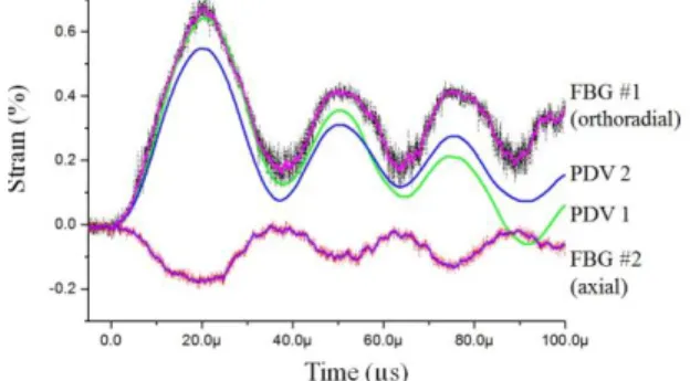
Fig. 2 depicts typical axial (a) and orthoradial (o) strains recorded with the FBG mainframe. Orthoradial strains calculated from PDV-recorded radial displacements are depicted as well. Both results are in accordance, allowing to foresee the use of FBGs for shock experiments with HPP in the purpose of improving Magneto-Hydro-Dynamics (MHD) codes. Further R&D work is focused on multipoint sensing with the aim of qualifying vibration modes.
Fig. 1. Layout of the HPP experiment
Fig. 2. Typical orthoradial and axial strains measured with the Bragg mainframe under HPP pulse (6 % MP). Comparison of orthoradial strains from the FBG and deduced from PDV-recorded displacements
4. References
[1] A. Lefrançois, P-Y.Chanal, G. Le Blanc, J. Petit, G. Avrillaud, M. Delchambre, “High Velocity Flyer Plate Developments on two High-Pulsed Power Generators Based on a Strip Line Design (GEPI, CEPAGE),” 15th Int. Symp. Electromag. Launch Metrology, 17-20/5, Brussels (2010) [2] J. Petit, “Materials under Extreme Loadings,” Ch. 14 (ISTE Ltd and John Wiley & Sons Inc., 2010)
[3] S.M. Melle, K. Liu, R.M. Measures, “Practical Fiber-Optic Bragg Grating Strain Gauge System,” Appl. Opt., 32 (19), 3601-3609 (1993) [4] S. Kim, S. Kim, J. Kwon, B. Lee, “Fiber Bragg Grating Strain Sensor Demodulator using a Chirped Fiber Grating,” IEEE Phot. Tech. Lett., 13 (8), 839-841 (2001)