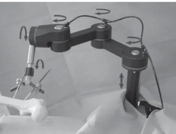
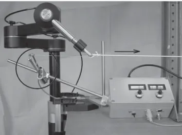
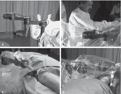
Passive Pneumatic Stabilization Device for Assisting in Reduction of Femoral Shaft Fractures
7
0
0
Texte intégral
Figure
Documents relatifs