Introduction
The insertion of interbody cages into the intervertebral disc space aims at providing mechanical stability through an implant made from a strong material, and at promoting fusion through the autogenous bone graft included in the cage. To enable fusion, a sufficient amount of potentially osteogenic cells is necessary [4]; therefore, bleeding bone has to be present next to the graft. Today, different cage designs require different endplate preparations. Basically,
two techniques can be distinguished: one includes deliber-ate endpldeliber-ate cavitation to provide a host bed of bleeding cancellous bone; the second technique involves excision of the cartilage endplate down to the preserved, bleeding subchondral bone.
To evaluate the importance of the endplate–cage inter-face, the way the endplate affects the behaviour of a func-tional spinal unit (FSU) must be known. The shape, den-sity and the strength of the endplate have been shown to vary across its surface, with the centre being the thinnest and weakest area [8, 11, 31, 39]. During compression test-Abstract Intervertebral cages in the
lumbar spine represent an advance-ment in spinal fusion to relieve low back pain. Different implant designs require different endplate prepara-tions, but the question of to what ex-tent preservation of the bony end-plate might be necessary remains unanswered. In this study the effects of endplate properties and their dis-tribution on stresses in a lumbar functional spinal unit were investi-gated using finite-element analyses. Three-dimensional finite-element models of L2-L3 with and without a cage were used. An anterior ap-proach for a monobloc, box-shaped cage was modelled. The results showed that inserting a cage increased the maximum von Mises stress and changed the load distribution in the adjacent structures. A harder end-plate led to increased concentration of the stress peaks and high stresses were propagated further into the ver-tebral body, into areas that would usually not experience such stresses.
This may cause structural changes and provide an explanation for the damage occurring to the underlying bone, as well as for the subsequent subsidence of the cage. Stress distri-butions were similar for the two end-plate preparation techniques of com-plete endplate preservation and par-tial endplate removal from the cen-tre. It can be concluded that cages should be designed such that they rely on the strong peripheral part of the endplate for support and offer a large volume for the graft. Further-more, the adjacent vertebrae should be assessed to ensure that they show sufficient density in the peripheral regions to tolerate the altered load transfer following cage insertion un-til an adequate adaptation to the new loading situation is produced by the remodelling process.
Keywords Finite-element analysis · Lumbar spine · Intervertebral cage · Stress distribution · Endplate Anne Polikeit
Stephen J. Ferguson Lutz P. Nolte Tracy E. Orr
The importance of the endplate
for interbody cages in the lumbar spine
Received: 5 December 2002 Revised: 4 March 2003 Accepted: 19 March 2003 Published online: 29 May 2003 © Springer-Verlag 2003
A. Polikeit · S. J. Ferguson · L. P. Nolte ·
T. E. Orr
M.E. Müller Institute for Surgical Technology
and Biomechanics, University of Bern, Bern, Switzerland
A. Polikeit (✉)
M.E. Müller Research Center for Orthopaedic Surgery, Institute for Surgical Technology and Biomechanics, Murtenstrasse 35, Postbox 8354, 3001 Bern, Switzerland Tel.: +41-31-6328720, Fax: +41-31-6324951, e-mail: [email protected]
ing of cages in the lumbar spine [15], the observed failure mode was fracture of the endplates. The large range of measured failure loads overlapped the potential in vivo loads, implying that failure of the endplate–implant inter-face may occur clinically. Questions regarding whether preservation of the bony endplate is necessary, or if partial conservation may be sufficient, or if it may not be re-quired at all remain unanswered. Hollowell et al. [12], for instance, assessed the importance of the endplate in resist-ing subsidence of various constructs and reported that the endplate did not increase the resistance significantly when tested until failure. However, most of the tested constructs were made from bone, and the only metal cage investi-gated was evaluated exclusively on an intact endplate. Closkey et al. [6] performed destructive and non-destruc-tive tests compressing a polymethylmethacrylate block on thoracic vertebral bodies. The bony endplate had been re-moved and a necessary minimum contact area to prevent subsidence at moderate loads was suggested. Steffen et al. [35] assessed the axial compressive strength of a mono-bloc implant with peripheral endplate contact as opposed to full surface contact. Peripheral endplate support was found to provide similar axial mechanical strength to that of a cage with full support.
However, the influence of the endplate quality on the load transfer in the lumbar spine has not been investigated previously, as has been done for cancellous bone density [29]. The aim of this study, therefore, was to evaluate the importance of endplate properties and their distribution for stresses in an FSU with and without an intervertebral cage.
Materials and methods
A previously developed [29], physiological finite-element model of a ligamentous L2-L3 FSU and a model with cage were used for this study (Fig. 1). Details of the model development have been given elsewhere [29], and are briefly summarised here. The geom-etry of the model was based on computed tomographic (CT) scans from a healthy young cadaver specimen. Details that were not clearly visible on the CT scans were modelled according to addi-tional data [29]. The assigned material properties were adapted from previous finite-element studies and assumed to be linear, ho-mogeneous and isotropic [10, 20, 32, 33, 34]. Seven different
liga-ments were included, being active in tension only, and the intact fi-nite-element model consisted of 31,714 elements. An anterior ap-proach for a monobloc, box-shaped cage, based on the Syncage (Mathys Medical Ltd., Bettlach), was modelled. The cage size was chosen according to the space between the vertebrae, as proposed by the manufacturer to restore lordosis and disc height. The origi-nal convex shape of the implant was not included in the model, as the fit between the curved endplates and a flat implant would rep-resent the severe loading case of edge contact, and is realistic for quite a number of existing cages. To fit the cage, the anterior lon-gitudinal ligament, the nucleus pulposus and the necessary amount of fibre and annular elements were removed.
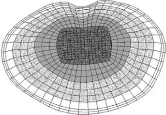
To investigate the influence of the endplate on the load trans-fer, the inferior endplate of the L2 vertebra and the superior one of L3 were altered. No cartilaginous endplates were defined on the bony ones, as their effect on the load transfer was assumed to be negligible; furthermore, the cartilaginous endplate is usually re-moved prior to cage insertion. The shape of the bony endplates was in accordance with the reported observations [8, 31]. According to the published mean values, the endplate was modelled thicker ad-jacent to the annulus (0.85 mm) than in the central region (0.45 mm). The endplate material properties were varied in both models to represent a wide spectrum of bone qualities, ranging from the stiff-ness of the underlying cancellous bone up to that of cortical bone, i.e. 100, 600, 1000, 6000 and 12,000 MPa. Furthermore, alterations to the properties of the endplate correspond indirectly to the differ-ent techniques of endplate preparation. For example, setting the endplate modulus equal to that of the underlying cancellous bone (100 MPa) would be mechanically equivalent to surgical removal of the endplate. As, additionally, the strength has been shown to vary across the endplate [11], two non-homogeneous distributions of endplate properties were modelled: a rough distribution with four different moduli defined across the surface (Fig. 2), and a fine distribution for which the outer three “rings” of the rough distribu-tion were further divided such that each ring of elements had a dif-ferent property assigned.
Failure load and strength of endplates have been determined experimentally [11], but their relation to the elastic modulus of the structure is unknown. Therefore, two different variations were modelled, using the values of the moduli assigned in the homoge-neous cases. For the “soft endplate”, the modulus in the middle area (darkly shaded in Fig. 2) was the same as for cancellous bone – 100 MPa – and roughly or finely increased to 1000 MPa – the endplate property of the “normal” model – in the outermost ring. This model may be considered equivalent to the case of partial endplate excision in the middle of the vertebra. In the model with a “hard endplate” a modulus of 1000 MPa was assigned to the mid-dle area, and increased up to 12,000 MPa – similar to the cortical shell modulus – in the outermost ring. This model would probably represent the physiological situation most precisely. Nine different
Fig. 1 The intact finite-element model (left) and the model with
cage (right)
Fig. 2 Rough distribution of endplate properties; each grey shade
definitions of endplate properties were thus evaluated in the intact finite-element model and nine in the model with cage.
Gap elements were used for the contact interfaces between the cage and the endplate, with the contact direction being perpendic-ular to the cage surfaces. As most intervertebral implants have small teeth or serrations on the contact surfaces, a friction coeffi-cient of 0.8 was defined between the cage and the adjacent end-plates. The three possible translation components of the inferior surface of the L3 vertebra were fixed in space. As the loading con-ditions and the cage material were shown to have a minor influ-ence on the load transfer compared to a cage insertion [29], a tita-nium implant was modelled and exclusively pure compression of 1000 N was applied to all models.
Results
Increasing the endplate modulus changed the von Mises stress distribution in the adjacent structures. The altered stress distribution in the cancellous bone of L3 for the in-tact models is shown in Fig. 3. Stress alterations mainly occurred in the regions directly adjacent to the endplate. The harder the endplate, the smaller the maximum stress in the trabecular bone was, as can be seen in the decreas-ing amount and size of black areas in Fig. 3 and in Fig. 4. Whether the elastic moduli were varied roughly or finely across the endplate had a negligible influence on the stress distribution in the cancellous bone; a similar result was
seen. With a stiffer endplate, load is shifted from the can-cellous core to the vertebral cortex.
Due to the above-described findings, a representative subset of all solved models for the comparison of the in-tact case to the model with cage is presented to facilitate understanding. The results of models with a uniform end-plate modulus of 100 MPa, i.e. similar to cancellous bone, 1000 MPa, the “normal” one, and 12,000 MPa, similar to cortical bone, are therefore presented along with the re-sults of models with soft and hard endplates derived from the fine distribution of the moduli.
The maximum von Mises stress in the cancellous bone of L3 decreased with increasing endplate stiffness (Fig. 4). That was true in the intact cases as well as in the models with cage, but to a different degree. It is also clearly visi-ble that the magnitude of the stress following cage inser-tion exceeded the stress in the intact case.
Inserting a cage altered the stress distribution in the FSU more than did the variation of the endplate modulus (Fig. 5, Fig. 6). The harder the endplate, the more the stress was concentrated in the contact areas between cage and bone. Whereas in the intact models the stress was slightly concentrated in the centre if the modulus was in-creased, it progressed deeper into the bodies in the pe-ripheral areas if a cage was inserted.
Fig. 3 Von Mises stress
distri-butions for intact models under axial compression. A sagittal cut through the cancellous core of L3 is shown, anterior is to
the left. The assigned endplate
modulus is given in the bottom
row
Fig. 4 Maximum von Mises stress in the cancellous core of L3: on
the left side in the intact case, on the right side in the models with cage. The corresponding endplate modulus is given in the legend
Fig. 5 Von Mises stress distributions for intact cases (upper row)
and models with a titanium cage (bottom row). A sagittal cut through the cancellous core of L3 is shown, anterior is to the left. The corresponding endplate modulus is given in the middle
This finding was confirmed when the stress magni-tudes were considered. Examples for the percentile differ-ences of the stress maxima in the L3 vertebral body be-tween an intact and a cage model due to varied endplate properties are depicted in Table 1. Results from discrete element subsets are presented. These element subsets A (anterior), B (middle), C (posterior) were lying in the sagittal plane of the vertebral body of L3. The locations below the central slot of the modelled implant, two ele-ment layers away from the endplate, were chosen to min-imize possible artefacts resulting from contact force peaks. The redistribution of stresses towards the periph-eral regions after cage insertion is apparent for all cases.
The stress distribution in the endplate itself was altered due to the definition of a non-homogeneous material dis-tribution, but these differences did not propagate further. Comparing the resulting stress distribution in the cancel-lous bone (Fig. 5, 6), for example, only minor differences could be detected that might be caused by this variation of the endplate properties. In all cases, increasing the
end-plate modulus led to more prominent changes in the stress values and distribution after cage insertion as compared to the intact case.
Discussion
The introduction of intervertebral cages for spinal fusion has been a promising innovation [1, 5, 18, 19, 28, 30]; nevertheless, there is ongoing debate regarding the neces-sary conditions as well as the criteria for successful fusion [21, 25, 36]. The presented work evaluated the influence of endplate material properties on the stress distribution in a lumbar FSU. Inserting a cage increased the stress and markedly altered the overall load transfer under all cir-cumstances investigated. A harder endplate led to increased concentration of the stress peaks, and high stresses were propagated further into the vertebral body, into areas that would usually not experience similar stresses.
Although the presented finite-element models were based on physiological material properties and accurate spinal geometry, including ligaments, there were some limitations. For most materials, the corresponding prop-erty definitions were homogeneous. A more physiological material distribution in all structures may have produced different stress distributions. Nevertheless, non-uniform material distribution in finite-element models may also in-troduce numerical uncertainties.
The vertebral endplate and the underlying cancellous bone are known as preferential fracture locations in the vertebral body [8, 13, 14, 37], and subsidence of inter-body fusion constructs in adjacent endplates is a frequent mode of failure [7, 11, 15, 16, 21, 35]. Nevertheless, whereas the cancellous bone of the vertebra has been the subject of numerous studies [17, 22, 23, 24, 26, 27], the literature concerning the vertebral endplate is compara-tively sparse. Wenger et al. [38] evaluated the mechanical properties of the osseous endplate in bending and tension, reporting differences in material properties between nor-mal and diseased specimens. This variation could not be attributed to differences in bone mineral density (BMD) [39]. In the frontal plane the BMD was described to be higher at the periphery and lowest in the middle of the endplate. Variation of endplate thickness has been re-ported, with the anterior and the posterior regions being thicker than the central part [8, 31]. Grant et al. [11] de-termined highly significant regional strength and stiffness differences in the lumbar and sacral endplates, with the centre of the endplate being the weakest region. These variations were included in some of the presented models, but the varied endplate properties only altered the stress distribution in the endplate itself. It did not cause observ-able changes in the adjacent structures. Therefore, the de-finition of a single elastic modulus for the entire endplate seems to be justified for general analyses concerning the behaviour of a complete FSU. Investigations of fracture patterns in the endplate and the vertebral body, for exam-Table 1 Percentages of the maximum von Mises stress in the
sub-sets A (anterior), B (middle), C (posterior) in the sagittal plane of the lower vertebra due to varied endplate properties. The corre-sponding intact models were set to 100%
Model with: A B C
Endplate elastic modulus 100 MPa 155 36 90 Endplate elastic modulus 1000 MPa 207 32 134 Endplate elastic modulus 12,000 MPa 212 36 165 Soft endplate (100–1000 MPa) 203 29 116 Hard endplate (1000–12,000 MPa) 214 33 150
Fig. 6 Von Mises stress distributions for intact cases (upper row)
and models with a titanium cage (bottom row). A sagittal cut through the cancellous core of L3 is shown; anterior is to the left. The corresponding endplate definition is denoted in the middle, obtained with a fine distribution of the moduli
ple, would in contrast require a more detailed and appro-priate definition.
The consequences of complete and partial endplate ex-cision, as well as endplate preservation, can be inferred from these finite-element models. For the flat-interface mono-bloc cage type investigated, contact pressure was found to be concentrated around the edges of the implant, producing stress concentrations that could probably be tolerated by this strong part of the endplate. In contrast, reliance of this implant on cancellous bone, after endplate removal, may present an increased risk of cage subsidence. The strength of the vertebra–cage interface is not influenced by the end-plate alone, but also by the properties of the underlying bone. It has been assumed that the centre of the vertebral body is weaker than the periphery, which is supported by the fact that the distance between trabeculae increases in the vertebral centre [11]. Nevertheless, only a few biome-chanical studies have been conducted to evaluate the re-gional differences in the vertebral body and their influence on its strength. Antonacci et al. [2] showed the bone den-sity in the anterior region of the vertebral body to be higher than in other regions, regardless of overall density. In con-trast, Banse et al. [3] reported the cancellous bone density to be higher in core samples from the posterior region than in those obtained anteriorly or laterally. The central area of the vertebral body was not explicitly evaluated in either study; however, Edwards et al. have reported the centre of the endplate to be more porous [8]. In this study, a second continuous layer of dense bone was observed adjacent to the endplate in many lumbar vertebrae examined in the midsagittal plane. It is unclear why this structural feature was not seen in all vertebrae, or how it might affect stiff-ness and strength. In general, more literature concerning structural variations can be found than studies assessing the regional differences of strength and stiffness. This makes it difficult if not impossible to provide a complete picture of the dangers and failure probabilities due to cage insertions. Nevertheless, it can be concluded that placement of im-plants in the central area of the vertebral body could cause early failure. For the investigated implant shape, in trast, contact between the cage and the endplates was con-centrated at the periphery of the cage.
Using physiological finite-element models of an FSU enabled the assessment of the influence of endplate mate-rial and its distribution on the stresses in the vertebrae. By calculating the stress distribution for the entire motion seg-ment, it was demonstrated how much the overall stresses are affected by cage insertion. These changes cannot be assessed with experimental methods except at discrete lo-cations [9]. In addition, the variability resulting from dif-ferent cadaver specimens used in experimental studies was removed. The alteration of the load transfer is likely to cause structural changes in the adjacent bone. These changes may offer an explanation for the damage occur-ring to the underlying bone, as well as for the subsequent subsidence of the cage. Nevertheless, they also offer the possibility of adaptation to the new loading pattern.
Conclusion
The distinction between failure and success of fusion is influenced by a number of different parameters. Cage in-sertion was shown to change the overall load transfer un-der static loads, whereby the material properties of the cancellous bone and the endplate were found to be more important factors for the resulting stress than the cage ma-terial or the loading conditions [29]. Summarising our previous work in this area, it can be concluded that cages should be designed such that they rely on the strong pe-ripheral part of the endplate to reduce the risk of subsi-dence, and additionally offer a large volume for the bone graft and a big area for the interface between the graft and the bleeding bone in the middle. Furthermore, care should be taken to confirm that the neighbouring vertebral bodies show sufficient bone density in the peripheral regions, so that the altered load transfer following cage insertion can be supported until the remodelling process produces an adequate adaptation to the new loading situation.
Acknowledgements The authors thank Dr. Qingmao Hu for
as-sistance with the segmentation of the CT slices.
1. Agazzi S, Reverdin A, May D (1999) Posterior lumbar interbody fusion with cages: an independant review of 71 cases. J Neurosurg 91:186–192 2. Antonacci MD, Hanson DS, Leblanc
A, Heggeness MH (1997) Regional variations in vertebral bone density and trabecular architecture are influenced by osteoarthritic change and osteoporo-sis. Spine 22:2393–2401
3. Banse X, Devogelaer J, Munting E, Delloye C, Cornu O, Grynpas M (2001) Inhomogeneity of human verte-bral cancellous bone: systematic den-sity and structure patterns inside the vertebral body. Bone 28:563–571 4. Boden S, Sumner D (1995) Biologic
factors affecting spinal fusion and bone regeneration. Spine 20:102S–112S
5. Brantigan JW, Steffee AD, Lewis M, Quinn L, Persenaire J (2000) Lumbar interbody fusion using the Brantigan I/F cage for posterior lumbar interbody fusion and the variable pedicle screw placement system: two-year results from a Food and Drug Administration investigational device exemption clini-cal trial. Spine 25:1437–1446
6. Closkey RF, Parsons JR, Lee CK, Blacksin MF, Zimmerman MC (1993) Mechanics of interbody spinal fusion. Analysis of critical bone graft area. Spine 18:1011–1015
7. Diedrich O, Perlick L, Schmitt O, Kraft CN (2001) Radiographic charac-teristics on conventional radiographs after posterior lumbar interbody fusion: comparative study between radio-translucent and radiopaque cages. J Spinal Disord 14:522–532 8. Edwards WT, Zheng Y, Ferrara LA,
Yuan HA (2001) Structural features and thickness of the vertebral cortex in the thoracolumbar spine. Spine 26: 218–225
9. Frei H, Oxland TR, Rathonyi GC, Nolte LP (2001) The effect of nu-cleotomy on lumbar spine mechanics in compression and shear loading. Spine 26:2080–2089
10. Goel VK, Kong W, Han JS, Weinstein JN, Gilbertson LG (1993) A combined finite element and optimization investi-gation of lumbar spine mechanics with and without muscles. Spine 18:1531– 1541
11. Grant J, Oxland T, Dvorak M (2001) Mapping the structural properties of the lumbosacral vertebral endplates. Spine 26:889–896
12. Hollowell J, Vollmer D, Wilson C, Pintar F, Yoganandan N (1996) Bio-mechanical analysis of thoracolumbar interbody constructs. How important is the endplate? Spine 21:1032–1036 13. Holmes A, Hukins D, Freemont A
(1993) End-plate displacement during compression of lumbar vertebra-disc-vertebra segments and the mechanism of failure. Spine 18:128–135
14. Ikeuchi M, Yamamoto H, Shibata T, Otani M (2001) Mechanical augmenta-tion of the vertebral body by calcium phosphate cement injection. J Orthop Sci 6:39–45
15. Jost B, Cripton P, Lund T, et al (1998) Compressive strength of interbody cages in the lumbar spine: the effect of cage shape, posterior instrumentation and bone density. Eur Spine J 7:132– 141
16. Kettler A, Wilke H-J, Dietl R, Kram-mer M, Lumenta C, Claes L (2000) Stabilizing effect of posterior lumbar interbody fusion cages before and after cyclic loading. J Neurosurg 92:87–92
17. Kothari M, Keaveny TM, Lin JC, Newitt DC, Genant HK, Majumdar S (1998) Impact of spatial resolution on the prediction of trabecular architecture parameters. Bone 22:437–443
18. Kuslich S, Ulstrom C, Griffith S, Ahern J, Dowdle J (1998) The Bagby and Kuslich method of lumbar interbody fusion: history, techniques, and 2-year follow-up results of a united states prospective, multicenter trial. Spine 23: 1267–1279
19. Kuslich S, Danielson G, Dowdle J, et al (2000) Four-year follow-up results of lumbar spine arthrodesis using the Bagby and Kuslich lumbar fusion cage. Spine 25:2656–2662
20. Lu M, Hutton WC (1996) Do bending, twisting, and diurnal fluid changes in the disc affect the propensity to pro-lapse? A viscoelastic finite element model. Spine 21:2570–2579 21. McAfee P (1999) Interbody fusion
cages in reconstructive operations on the spine; current concepts review. J Bone Joint Surg Am 81:859–880 22. Millard J, Augat P, Link T, et al (1998)
Power spectral analysis of vertebral trabecular bone structure from radio-graphs: orientation dependence and correlation with bone mineral density and mechanical properties. Calcif Tis-sue Int 63:482–489
23. Mosekilde L (1993) Vertebral structure and strength in vivo and in vitro. Calcif Tissue Int 53:S121–S125; (S126 dis-cussion)
24. Mosekilde L, Mosekilde L, Danielsen CC (1987) Biomechanical competence of vertebral trabecular bone in relation to ash density and age in normal indi-viduals. Bone 8:79–85
25. Mulholland R (2000) Cages: outcome and complications. Eur Spine J 9: S110–S113
26. Odgaard A (1997) Three-dimensional methods for quantification of cancel-lous bone architecture. Bone 20:315– 328
27. Overaker D, Langrana NA, Cuitino A (1999) Finite element analysis of verte-bral body mechanics with a nonlinear microstructural model for the trabecu-lar core. J Biomech Eng 121:542–550 28. Pavlov P, Spruit M, Havinfa M,
An-derson P, van Limbeek J, Jacobs W (2000) Anterior lumbar interbody fu-sion with threaded fufu-sion cages and autologous bone grafts. Eur Spine J 9:224–229
29. Polikeit A, Ferguson S, Nolte LP, Orr T (2002) Factors influencing stresses in the lumbar spine after the insertion of intervertebral cages: finite element analysis. Eur Spine J DOI 10.1007/ s00586-002-0505-8
30. Ray C (1997) Threaded titanium cages for lumbar interbody fusions. Spine 22: 667–680
31. Roberts S, McCall I, Menage J, Had-daway M, Eisenstein S (1997) Does the thickness of the vertebral subchon-dral bone reflect the composition of the intervertebral disc? Eur Spine J 6:385– 389
32. Shirazi-Adl SA, Shrivastava SC, Ahmed AM (1984) Stress analysis of the lumbar disc-body unit in compres-sion. A three-dimensional nonlinear fi-nite element study. Spine 9:120–134 33. Shirazi-Adl A, Ahmed AM,
Shrivas-tava SC (1986) Mechanical response of a lumbar motion segment in axial torque alone and combined with com-pression. Spine 11:914–927
34. Silva MJ, Keaveny TM, Hayes WC (1997) Load sharing between the shell and centrum in the lumbar vertebral body. Spine 22:140–150
35. Steffen T, Tsantrizos A, Aebi M (2000) Effect of implant design and endplate preparation on the compres-sive strength of interbody fusion con-structs. Spine 25:1077–1084
36. Steffen T, Tsantrizos A, Fruth I, Aebi M (2000) Cages: designs and concepts. Eur Spine J 9 [Suppl 1]:S89–S94 37. van Dieën J, Kingma I, Meijer R,
Hänsel L, Huiskes R (2001) Stress dis-tribution changes in bovine vertebrae just below the endplate after sustained loading. Clin Biomech 16:S135–S142 38. Wenger KH, Wilke H-J, Pross A,
Claes LE (1997) Mechanical and ultra-structural properties of the osseous ver-tebral endplate. Annual report of the Institut für Unfallchirurgische Forschung und Biomechanik, Ulm 39. Wenger K, Pross A, Wilke H-J, Gossee
F, Vahldiek M, Claes LE (1999) Bone mineral density of the vertebral end-plate: an in vitro comparison of nor-mals, degeneratives and osteoporotics. 26th Annual Meeting, ISSLS, Kona, Hawaii