Design and large deformation response of
additively-manufactured shell-lattices
by Colin Bonatti
Ing6nieur dipl6md de l'Ecole Polytechnique (2013) Master of Science, Massachusetts Institute of Technology (2015)
Submitted to the Department of Mechanical Engineering in partial fulfillment of the requirements for the degree of
Doctor of Philosophy in Mechanical Engineering at the
MASSACHUSETTS INSTITUTE OF TECHNOLOGY February 2019
Massachusetts Institute of Technology 2019. All rights reserved.
Signature redacted
A uthor...
Colin Bonatti Department of Mechanical Engineering
Signature redacted
December 18th2018
Certified by...
Tomasz Wierzbicki Professor of Applied Mechanics Thesis Supervisor
Signature redacted
Certified by.... ...
Dirk Mohr
Professor, ETH Zurich
Signature redacted
Thesis SupervisorAccepted by... ...
MT I T Nicolas Hadjiconstantinou
MASSAH SETS NSTTUTE Professor, Graduate Officer
Department of Mechanical Engineering
LFEB
2
5
2019
LIBRARIES
Design and large deformation response
of additively-manufactured shell-lattices
by
Colin Bonatti
Submitted to the Department of Mechanical Engineering
on December 18th 2018 in partial fulfillment of the requirements for the degree of Doctor of Philosophy in Mechanical Engineering
Abstract
Open-cell cellular solids are porous structures with a large variety of applications, from energy absorption to medical engineering. In an attempt to identify isotropic configurations with high low and large strain mechanical properties, detailed numerical simulations are conducted on a wide range of mesostructures of cubic symmetry. Results are partially validated through uniaxial compression of specimens made of 316L stainless steel via selective laser melting. In a first study the large deformation responses of four different mesostructures of relative density 20% are compared: an octet truss-lattice, tube-lattice, a sphere assembly and a tube/sphere hybrid. It is concluded that periodic shell structures provide superior strength and energy absorption capacity for the same weight, as compared to truss-lattices. Another conclusion is that to avoid concentrations of plastic strains that are detrimental to the overall energy absorption of the structure, it is best to avoid peaks in curvature. Based on these conclusions, a shell-lattice is developed that resembles a smoothened Triply Periodic Minimal Surface of FCC symmetry. Its properties are compared to those of the octet-truss for a wide range of relative densities, revealing the shell-lattice as superior to the octet-truss in almost all cases. The FCC shell-lattice is then compared to its BCC and SC equivalents. It is found that the structures all present high anisotropic properties. For a given structure, directional difference factors of up to 4.1 in uniaxial stiffness, 2 in yield strength and 1.8 in specific energy absorption are observed. However the directional averages of their properties are very similar. Irrespective of the specific type of cubic symmetry, the shell-lattices are remarkably stiff, strong and energy-absorbing, particularly at relative densities above 0.1. To address the problem of anisotropy, novel families of shell-lattices that contain the previous examples are proposed. Design maps are established and reveal that the elastic anisotropy of shell-lattices can be conveniently tailored. As a result, isotropic topologies are identified. The elastically-isotropic shell-lattices feature similar overall performance that their TPMS-like counterparts as well as a significantly reduced plastic anisotropy. The structures obtained are believed to be the best performing open-cell topologies to date.
Acknowledgements
I would like to thank my two advisors, Professor Tomasz Wierzbicki and Professor
Dirk Mohr, for their support and their guidance during the years I spent as a Graduate Student at MIT. I appreciate the trust they showed in my abilities, and the fantastic opportunity they gave me to pursue and develop my own ideas. I appreciate the guidance and help I received from them when I found myself in need of it.
I am grateful Professor Katia Bertoldi, Professor Lallit Anand and Professor John Hart
for agreeing to sit on my committee and discuss my research.
None of this would have been possible without the help, the support and the friendship of my colleagues: Professor Yong Xia, Professor Dr. Marcelo Paredes, Professor Vincent Grolleau, Dr. Christian Roth, Dr. Maysam Gorji, Dr. Matthieu Dunand, Dr. Stdphane Marcadet, Dr. Kai Wang, Dr. Xiaowei Zhang, Dr. Keunhwan Pack, Dr. Chus Perez-Martin, Dr. Borja Erice, Dr. Michal Bardadyn, Mr. Rami Abi Akl, Mr. Thomas Tancogne-Dejean, Ms. Marianna Diamantopoulou, Mr. Charles Boubert, Mr. Alexis Leautier, Mr. Hailing Luo, Mr. Kyle Miller, Mrs. Brandy Dixon, Mr. Yannik Sparrer, Mr. Benoit Jordan, Mr. Julian Heindenreich, Mr. Thomas Beerli, and Ms. Franziska Siebenbrock.
Thank you to Leslie Regan and Barbara Smith for making my life so much easier here. Finally, I would like to thank my friends and my family for supporting me during all these years.
The financial support of the MIT Fracture Consortium and the Swiss National Foundation, are gratefully acknowledged.
Table of Contents
1. IN TR O D U C TIO N... 9
1.1. M ICRO, M ACRO AND M ESO-STRUCTURE... 9
1.2. CELLULAR MATERIALS... 9
1.3. M ECHANICAL PROPERTIES...10
1.4. STOCHASTIC FOAMS...16
1.5. LATTICE-M ATERIALS...18
1.6. THE IM PORTANCE OF ISOTROPY ... 22
1.7. STATEM ENT OF CONTENTS...23
2 . M ETH O D S...25
2.1. STRUCTURES OF CUBIC SYMMETRY ... 25
2.2. FINITE-ELEM ENT ANALYSIS...32
2.3. EXPERIM ENTAL METHODS ... 38
3. COMPARED ANALYSIS OF SEVERAL FCC METAMATERIALS...44
3.1. STRUCTURES CONSIDERED...44
3.2. FINITE ELEM ENT ANALYSIS...50
3.3. EXPERIM ENTS...67
3.4. CONCLUSIONS...84
4. FROM OCTET-TRUSS TO FCC SHELL-LATTICE...86
4.1. GENERATION OF SM OOTH-SHELL STRUCTURES...86
4.2. COMPUTATIONAL MODELS...93
4.3. EXPERIM ENTAL PROCEDURES...99
4.4. RESULTS...101
4.5. CONCLUSIONS...114
5. MECHANICAL BEHAVIOR OF CUBIC SHELL-LATTICES ... 116
5.1. M ETAM ATERIALS INVESTIGATED...116
5.2. NUM ERICAL ... 120
5.3. EXPERIM ENTAL ... 123
5.4. RESULTS...128
5.5. D ISCUSSION ... 143
6. TOWARDS ISOTROPIC SHELL-LATTICES...145
6.1. SMOOTH-SHELLS, MINIMAL SURFACES AND LEVEL-SET APPROXIMATIONS ... 145
6.2. VARYING THE FUNCTIONAL...151
6.3. BEHAVIOR OF AN ISOTROPIC SHELL-LATTICE...157
6.4. SUM MARY ... 162
7 . SUM M A R Y AN D O U TLO O K ... 163
7.1. SUM MARY ... 163
7.2. O UTLOOK ... 165
8 . A PPEN D IX ... 169
8.1. RELATIVE DENSITY DERIVATION FOR THE H TS STRUCTURE ... 169
8.2. SHELL-LATTICE MATERIALS: BENDING OR STRETCHING DOMINATED? ... 172
1. Introduction
1. .Micro, macro and meso-structure
Material properties are a function not only of the material's chemical composition but also its internal structure. Perhaps the most striking example of is that of carbon, which exists in nature as two different materials, graphite and diamond, with vast differences in their properties. Another famous example is the grain boundary strengthening (or Hall-Petch effect) observed in polycrystalline metals: as crystal grains grow smaller the overall material grows stronger. It should be noted that the two afore-mentioned examples relate two different length-scales: typical grain sizes in polycrystalline metals are typically expressed in micrometers while the lattice constant for diamond is a few angstroms. However they both refer to the microstructure of the material. As pointed out by Lee et al.
(2010), tailoring the microstructure of materials is one of two original strategies that
mankind has used to modify their properties, as exemplified by the manufacturing of amorphous glass windows or of special steels with highly anisotropic microstructures. The other approach is at a completely different scale: that of the macrostructure of an application, best exemplified by the use of beams and arches by architects. As manufacturing techniques advanced, mankind was able to produce composite materials, such as concrete blocks reinforced by metal fiber. At a scale larger than that of the microstructure of either of its constituent materials, and smaller scale than that of the macrostructure of the building and the beams, plates or staircases it composes, the arrangement of steel bars in the concrete matrix is referred to as the mesostructure. The mesoscale, is that of the arrangement of the different materials within the composite. In more recent developments, materials whose mesostructure allows them do develop uncommon sets of properties have been referred to as metamaterials. A common goal of metamaterial design is to advantageously combine the properties of two different materials.
1.2. Cellular materials
Cellular materials constitute one special class of metamaterials, where one of the constituents is air (or void). They are porous solids, but with high porosities that often make
up for most of the material volume. Because of this cellular solids are in essence clusters of cells of air (hence their name), delimited by a solid structure composed of either beams or shells. Note that while simpler, cellular materials with prismatic cells (2D cellular materials) escape the scope of this thesis. The reference text on cellular materials is the book Cellular solids: structure andproperties by Gibson and Ashby (1999). As they point out, cellular solids are widespread in nature and among the oldest materials used by man: examples include wood, cork, and sponge. Man-made cellular solids include widespread examples such as honeycombs used as sandwich cores for lightweight applications, and polymeric foams used in packaging. Less straightforward applications of cellular materials rely on mutltifunctionality and include metal foam coatings designed for orthopedic implants, heat exchangers, and the development of porous scaffolds for tissue engineering, among others (Gibson and Ashby 1999, Gibson et al. 2010). It should be noted that the last two mentioned examples imply permeability of the cellular material to a fluid.
1.3. Mechanical properties
1.3.1 Relative density
Due to the high porosity of cellular materials it is often more relevant describe them in terms of their relative density, instead of their porosity, i.e. the ratio of their density to the density of the constituent material. For a cellular solid of porosity cP, its relative density is equal to:
p =1- (1.1)
Ps
In fact, any given topology is usually referred to independent of its relative density, where it is understood that one parameter - the shell-thickness to length ratio, or the beam diameter to length ratio - controls the relative density of what is now a family of structures.
1.3.2 Linear properties
This thesis is mostly concerned with the determination of the mechanical, quasi-static properties of certain families of metallic cellular materials, notably under uniaxial
determining: the stiffness, the strength and the specific energy absorption. Their respective scaling is expressed in terms of the relative density. The elastic moduli of isotropic composite solids are bound in terms of the stiffness of the constituent materials. From variational principles, Hashin and Shtrikman (1963) derived inequalities that in the case of porous materials reduce to:
/-1 3 -1 0!K Ks +(1- P)- -- + 3P (1.2) Ks 3Ks +4Gs) 6 -1 6 (Ks + 2Gs)# 0 G Gs + (1 -) - + ( (1.3) GS (3Ks + 4GS)P1,
Where K and G are the bulk and shear moduli of the cellular material, and Ks and Gs are those of the constituent material. Given that the isotropy of the composite, a similar bound can be obtained for the Young's modulus E, using the relation:
9KG
E - (1.4)
3K+G
For demonstrations the reader is referred to Walpole (1966) or Willis (1977). Equivalents for strength exist (e.g. Suquet 1993). Stiffness and strength of cellular materials are essentially linear properties, and they are easily obtained from elastic simulations. As such they are fairly easy to obtain, and the results (their scalings) are essentially independent of the constituent material.
1.3.3 Energy absorption
This generality is lost for specific energy absorption which is on the contrary, intrinsically nonlinear. Energy absorption relates to mechanical energy effectively dissipated by the material through either plastic work (metals), viscous effects (polymers) or fracture (ceramics) - this property relates to large-deformation, inherently non-linear behaviors of both the structure and the constituent material. As a consequence, it is useful to explore some concepts drawing from a couple of uniaxial examples.
1.3.3.1 Uniaxial examples
Figure 1.1 a presents a typical engineering stress-strain curve corresponding to uniaxial compression for a bulk steel. Past the yield point there is a constant increase in the engineering stress, due to both strain hardening and the increase in area. Figure 1. 1b presents the typical response of structural elements used in practice for crashworthiness, in this case a prismatic column. It is a convenient prototype structure to study because the apparently straight plate assembly is converted upon crush into a double curvature shell assembly. Figure 1.1 c presents a view of a honeycomb, along with a diagram of the cross-section and a typical force displacement curve. A photo of a partial crushed column, along with a diagram of the cross-section are presented next to a typical load displacement curve. In both cases after reaching a peak load due to elastic or plastic buckling, the force drops down and then fluctuates around an average value, where the mean crushing force Pm is defined by:
Pm = - (6)d6 (1.5)
Where 6f is the final crush distance of the compressed column. The energy effectively absorbed, through plastic flow, during crushing is approximately equal to:
D = Pm5 (1.6)
The energy per unit mass is thus:
D
P =(1.7)
Where V is the volume of the prismatic column and p is the density of its constituent material. Similar load-displacement curves are obtained for various cross-sectional shapes such as circular, rectangular, single hat, double hat and hexagonal cross-section with flanges. The average crushing stress is defined as the mean average crushing force divided
by the tributary area:
am = PM (1.8)
At
Where the tributary area At is the cross-sectional area effectively occupied by the structure or honeycomb, included void areas. The honeycomb is a very efficient energy absorbent material in axial crushing. The crushing force in the lateral (in-plane) direction
is one or two orders of magnitude smaller depending on the aspect ratio. This gives rise to the very pronounced anisotropy of honeycombs. There is a large body of literature on predicting the mean crushing strength of simple prismatic columns subjected to axial compression. For example, for a square cross-section with a wall thickness t, and the width of a flange b, assuming a constituent material of density p and the energy equivalent flow stress co, the closed form solution for the mean crushing form is:
F = 12c0ts/3b /3 (1.9)
The range of validity of the above simple equation is 10t < b < 100t. For such a column the relative density (portion of space effectively occupied by the constituent material) reads:
4bt 4t
b2 b
The energy per unit mass therefore reads:
2
FE t 3 3 2
1p = 4pbt = 3Embo = Emaop3 (1.11)
The scaling is valid up to relative densities of 20%, up from which the column reacts through bulging rather than through crushing. This simple result illustrates that scalings of specific energy absorption with relative density in the power 2 / 3 emerge naturally when
crushing modes are the dominant response.
Another useful measure of the energy absorption capabilities is the engineering stress:
U = F= 3uO(t2/ (1.12)
Where A = 4bt is the actual area of the cross-section of the prismatic column (and not
of the tributary area). The upper limit of the engineering stress is the so-called squash stress
a = aO , which occurs when b = 5.2t. Such a thick-walled tube will flow plastically with no elastic or plastic buckling. The maximum stress is the in-plane compressive membrane stress. Thinner columns (b > 10t) will buckle plastically. The structure then finds a new bending-dominated equilibrium path, with local areas of tensile and compressive membrane stresses. While not discussed in the core of the thesis, a numerical investigation into the respective contributions to plastic dissipation of membrane and bending actions for the structures developed herein, was conducted. Its results are presented in Appendix
3, revealing similar trends: membrane action is dominant (70% to 80% of energy
dissipation) for thick, stable structures, while for thinner structures the associated buckling leads to even contributions of membrane and bending actions to the dissipation.
a) -T 2500 2000 1500 bO 1000 .2 500 M 0 b) .3 40. 201 0 0 0.2 0.4 Engineering strain [-3 0.6 b Peak force
k
Mean crushing force(\VI \f\
V
\)N-
\j \J \/
\j \
\\/V
IT
25 50 75 100 125 150 Axial Displacement 8 (mm] 175 200 225-N
L P 2h S D-S DisplacementFigure 1.1: a) Stress-strain curve of bulk steel under uniaxial compression. b) View of a compressed prismatic column, typical corresponding force displacement curve, along with diagram of the cross-section. c) View of an aluminum honeycomb, corresponding stress-strain curve, and diagram of cross-section.
I
1.3.3.2 A few words on energy absorption
Cellular materials have uniaxial behavior that that fall between the extreme examples presented in the previous paragraph. At large relative densities, they present a bulk-like response, with hardening throughout. At low relative densities, the engineering stress quickly reaches a peak, after which it drops to a plateau value around which it oscillates. Deterministic structures such as the prismatic column, present large and repeatable oscillations that correspond to a repeated crushing mode of successive layers of the structure, while stochastic structures such as foams (as will be shown later) have small oscillations, given that they present a large number of cells with different topologies and thus a large number of crushing mechanisms and associated forces, which blurs the response.
A difficult point concerns what measure of energy absorption should be used. Aside
from cost, two quantities influence the design and choice of material: the energy dissipated per unit mass (specific energy absorption) and the energy dissipated per unit volume (volumetric energy absorption). For any material, as the material gets compressed and compacted, the forces involved will diverge to infinity - in that sense the energy needed to fully compress the material is infinite. For the measure to have meaning, there needs to be a cutoff-strain Ef. If one neglects elastic energy, the specific energy absorption will then
read:
D 1 Ef
- = - - ~ a : d c (1.13)
P PJe=o
Where D is the plastic dissipation per unit volume. How should that cut-off strain be defined? This decision oftentimes driven by applications. In energy absorption applications, kinetic energy is absorbed by the structure in order to protect an object or a person from an impact and both the large forces associated. It makes sense, then to define the cutoff strain as the strain for which the maximum acceptable force is first observed. The energy absorbed per unit volume is then maximal if the stress-strain curve presents a long plateau, with a stress corresponding to the maximum acceptable, up to a very large densification strain. As explained above, all geometries will present that desirable plateau for low enough relative densities - however the poor scaling with relative density in that regime will lead to poor specific energy absorption.
In this thesis we not will attempt to estimate the densification strains of the cellular materials investigated. Instead we resort to a simpler definition of specific energy absorption that relies on a fixed cutoff strains for all structures.
1.4. Stochastic foams
Until about two decades ago, stochastic foams with cell sizes at the millimeter level were the only man-made cellular solids with nearly isotropic mechanical properties. Metal foams can be made through a variety of processes from vapor deposition or electrodeposition on a polymer foam (that is subsequently removed) to injecting bubbles of gas in molten metal (for more details, see Ashby et al. 2000). Two categories of foams can be distinguished. Open-cell cellular solids consist in a set of nodes connected by ligaments that exhibit a beam-like mechanical response, while closed-cell foams are composed of thin-walled plate-like elements. In their pioneering work, Gibson and Ashby
(1999) provide scalings for the mechanical properties of both categories. Those are based
on structural analysis of cells representative of the two architecture types. In what follows the subscripts Xc and Xc correspond to open-cell and closed-cell foams while X, corresponds to the constituent solid phase.
Open-cell Closed-cell
Young's modulus: Eoc Ecc
- - = C i p z_ z ( 1 # ) ;( 1 .1 4 )
Es Es
Shear modulus: Goc Gcc
--- Czz 22 + 1 -#);(1.15)
Gs Es
Poisson's ratio: (116)
vccvoc (.6
Elastic collapse: aec C #
Es 0.052 -Es 0.05z (1.17)
Plastic collapse: P1 P1
Oc 0.3#3/2 -"- 0.3 (#) 3
/ 2 + 0.4(1 - ); (1.18)
y,s Uy's
Where P is here a geometrical parameter accounting for excess matter in the ligaments bordering the cell walls. In the expressions for closed-cell foams, the contributions of the gas trapped within the cells has been omitted. The typical stress-strain curve for a
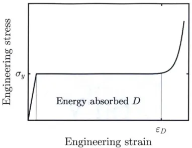
low-region, ended by a densification phase. The energy absorbed corresponds to the grey area under the curve in the plateau regime, up to a cutoff strain (here the densification strain).
r
Energy absorbed D4D
Engineering strain
Figure 1.2: Typical stress compression stress strain curve for a low density foam, showing elastic loading, a stress plateau and a densification regime.
In the correlations above, the estimated plastic stress corresponds to the plateau stress. Given our definition of energy absorption, ignoring elastic strains and for a cutoff strain
em below the densification strain, the plastic dissipation would read:
D = iayEm (1.19)
As can be seen above the mechanical properties of idealized closed-cell foams are far superior to those of open-cell foams, with linear scalings of both stiffness and strength (before plastic collapse dominates at extremely low relative densities). Using the more precise example of a tetrakaidecahedron foam, Simone and Gibson (1998) even estimated that at low relative densities:
Eccc.3ps(.1
However these close-to-optimal predicted behaviors are not observed in practice (e.g. Gibson (2000), Ashby et al. (2000)). In Metal
foams:
a design guide, Ashby et al. give thefollowing correlations for experimental data:
E aEs1i" with 1.8 n 2.2 (1.22)
Gibson (2000) notes that experimental data for closed-cell foams is better represented
by open-cell foams equations, and attributes the discrepancy to the influence of bending in
the response of curved cell walls. Evans et al. (1998) similarly attributes this knockdown in properties to morphological defects. Ashby (2006) summarizes that the actual behavior of open- and closed-cell stochastic foams is bending dominated (with the associated
sublinear scaling).
1. 5.Lattice-materials
1.5.1 Truss-lattices and plate-lattices
Different from stochastic structures, lattice-materials are deterministic periodic cellular materials. Truss-lattices are the deterministic equivalent of open-cell foams, just as plate-lattices are deterministic closed-cell foams. Perhaps due to manufacturing constraints, truss-lattices have received have been predominantly studied in the past two decades. Deshpande et al. (200 1a) showed that stretching-dominated truss-lattice materials significantly higher stiffness and strength than foams, with linear scalings of stiffness and strength properties (see also. Evans et al., 2001).
In engineering practice, metallic truss-lattices can be built from three-dimensionally formed perforated sheets (e.g. Sypeck and Wadley (2002), Wadley et al. (2003)). Alternatively, truss lattice metamaterials with solid struts can be readily obtained through additive manufacturing (e.g. Yan et al. (2012), Gumruk and Mines (2013), Stankovic et al.
(2015), Tancogne-Dejean et al. (2016)). The smallest achievable feature size of
state-of-the-art selective laser melting with metals is still of the order of about 30ym. Metallic structures with finer structural features can be fabricated by depositing metallic layers onto free-standing polymer scaffolds through electroless-plating, atomic layer deposition or RF sputtering. After removal of the polymeric support, hollow shell-like structures with nanometric wall thicknesses are obtained. It is noted that the same process also applies to making hollow ceramic nanostructures. The fabrication of porous solids with mesostructural features in the submicrometer range is mostly explored to leverage size effects in the solid base constituent. For example, Schaedler et al. (2011) produced a lattice
waveguide technique. Using electroless plating, they deposited thin nickel films with an average grain size of a few nanometers. Multiphoton lithography has been employed by Jang et al. (2013) and Montemayor et al. (2014) to produce solid polymer lattice templates with a few microns long struts. Jang et al. (2013) applied about 75nm thick ceramic layers onto the octet truss scaffold, thereby producing hollow TiN octet truss metamaterials with a base constituent strength of 1.7GPa. Bauer et al. (2014) employed 3D laser lithography along with atomic layer deposition to create cellular polymer mesostructures with 1 Onm to
200nm thick alumina coatings that exceeded the compressive strength of foams at effective
densities below 1 g/cm3.
Perhaps the best-known example is the octet-truss, of which Deshpande et al. (2001b) investigated the elastic and failure response both experimentally and analytically. The octet-truss's properties have been widely studied, including its macroscopic plastic behavior (Mohr, 2005), fracture toughness (O'Masta et al., 2017) and buckling-to-yield failure transition (Carlton et al., 2017). Elsayed and Pasini (2010) elaborated design maps for octet-truss-inspired lattices with simultaneous yield and buckling limits. This accumulated knowledge as well as its popularity make it an ideal candidate for comparisons, and it is the structure of choice for numerous studies on related topics. For example, scale effects in octet truss lattices made from copper with strut diameters of a few microns have been investigated by Wendy Gu and Greer (2015), while He et al. (2017) made use of molecular dynamics simulations in conjunction with theoretical models to assess the compressive response of copper nano-lattices with strut diameters of a few nanometers only, reporting significant property enhancement as compared to bulk copper. However, the linear scaling of truss-lattice properties often breaks down at low relative densities due to buckling instabilities (Deshpande et al. 2001b). This issue has been partially addressed by the design of hierarchical metamaterials which feature different levels of structure (e.g. Meza et al. (2015), Zheng et al. (2016)). Hierarchical design allows low relative densities to be reached for the overall structure while keeping mesostructural feature-level aspect ratios low enough to retard instability-driven failure. By hierarchically combining octahedral and octet-trusses, Meza et al. (2015) have been able to achieve the linear-scaling of the elastic and elastic limit properties down to relative densities of about 10-4.
It is now known that even optimal truss-lattice materials (Gurtner and Durand, 2014) cannot achieve the theoretical Hashin-Shtrikman stiffness bounds for isotropic cellular solids. At low relative densities, the highest achievable Young's modulus of stretching-dominated isotropic truss-lattice materials is about three times lower than the theoretical upper limit (Tancogne-Dejean and Mohr, 2018a). The latest studies on the stiffness and strength of mechanical metamaterials revealed that plate-lattices can attain the Hashin-Shtrikman and Suquet bounds (Berger et al. 2017, Tancogne-Dejean et al. 2018b). However, the closed-cell nature of optimal plate-lattices complicates their manufacturing through powder-bed or liquid-bath additive techniques. Moreover, similar to closed-cell foams, their lack of permeability limits their potential for multifunctional applications.
1.5.2 Shell-lattices
Another emerging category of metamaterial architectures next to truss- and plate-lattices are shell-plate-lattices, i.e. periodic structures composed of non-intersecting shells (e.g. Han et al., 2015). These open cell shell structures have the particularity of separating two fluid phases. This feature facilitates their production through additive manufacturing techniques that require the extraction of powder or liquids. Moreover, it makes them suitable for applications requiring multi-functionality such as mechanical resistance combined with heat exchange capability. Such surfaces naturally emerge in block copolymers where two macromolecules arrange at equilibrium by forming cocontinuous domains (e.g. Thomas et al. 1988). Constant mean-curvature surfaces, including the best-known Triply Periodic Minimal Surfaces (TPMS), and (mathematically simpler) level-set surfaces have been proposed as an approximation to the separating surface (e.g. Lambert et al. 1996). Following from those findings, cocontinuous composites, i.e. two-phase composites wherein each phase occupies the volume on one of the two sides of the limiting surface, have been proposed and their mechanical properties studied for a range of constituent materials.
Maldovan et al. (2007) studied the stiffness of microframes (solid/air composites) with several interface topologies, including some defined by level-set surfaces approximating the Schwarz P, I-WP and F-RD surfaces. Wang et al. (2011) used the same geometries to
respective phases was varied leveraging one degree of freedom in the level set function. They reported enhanced properties as compared to particle-reinforced composites, including increased damage tolerance. Topologically similar carbon/epoxy bicontinuous composites were produced by Lee et al. (2012) via a combination of 3D direct laser writing, pyrolysis and infiltration, and revealed to present specific energy absorptions of up to 720
kg/kJ. A similar approach consists in reinforcing a soft matrix through a uniform-thickness
shell with the analytical surface as a mid-surface instead of using "skeletal" truss-structures. Abueidda et al. (2015) analyzed numerically the thermal expansion of such cocontinuous composites, revealing a low coefficient of thermal expansion of interest for applications. Dalaq et al. (2016a, 2016b) studied numerically and experimentally the elastic modulus, strength, strain at failure and toughness of such composites (with varying TPMSs) consisting of a Tango-Plus matrix reinforced by TPMS-shaped Vero-Plus.
Foam-like shell-lattice materials can be obtained by retaining only the non-intersecting shell structures of uniform thickness. With the goal of identifying superior scaffold designs for tissue engineering, Kapfer et al. (2011) designed such shell-lattices and estimated their elastic properties, as well as their fluid permeability, numerically and compared those to TPMS-based skeletal networks of the same porosity, revealing superior mechanical properties. Han et al. (2015) proposed ultra-low density shell-lattices consisting of Schwarz P- and Schwarz D-surfaces. They optimized these structures for stiffness along one direction by reducing the nozzle size between neighboring cells while breaking down the cubic symmetry by elongating the unit-cell along the direction. Lee et al. (2017) investigated the stiffness and yield properties of shell-lattices based on the Schwarz-P minimal surface. Al-Ketan et al. (2017) studied the compressive behavior of steel-based
BCC metamaterials, including a BCC truss-lattice, and shell-lattice structures based on a
level-set approximation of the I-WP TPMS. They showed that the shell-lattice presented superior mechanical properties as compared to the truss-lattices. Bobbert et al. (2017) fabricated sixteen types of TPMS shell-lattices from Ti-6A1-4V, reporting low elastic properties, high strength, high fatigue resistance, and high permeability, thereby mimicking the properties of trabecular bone.
1.6. The importance of isotropy
As pointed out by Lee et al. (2012), an important aspect of mechanical metamaterials is the ability they give to design for structural anisotropy - giving the example of Damascus steel blades benefitting from an anisotropic microstructure. Metamaterials offer the opportunity to locally tailor the anisotropy to further enhance the performance in given applications. In cases where loadings are expected in one direction or within a plane, the desirable elastic response would likely be transverse isotropic. Given an elastically-isotropic material, a particularly simple way to obtain transverse-elastically-isotropic metamaterials is provided by results on foam elasticity (Gibson and Ashby, 1999). Most foams have structural anisotropy where their cells are more elongated in one direction than in the transverse plane. For a foam with an anisotropy ratio R, where R is the ratio of the longest to the smallest cell size in given directions, the ratio of their Young's moduli in the
direction of anisotropy El to the transverse Young's moduli Et is given by: - =
(1.24)
Et 1 + (1/R3)
Similarly, one could use elongate the mesostructures of elastically-isotropic metamaterials to tailor their anisotropy to the application. This further enhances the importance of finding high performance isotropic configurations.
However most configurations, even the most studied, are far from isotropic, despite often having cubic symmetry. For example the octet truss lattice is often perceived as an isotropic metamaterial, but it is worth noting that its mechanical response can be highly anisotropic. Two strategies have been used to obtain elastically-isotropic configurations: a superposition approach, and a variation approach.
Isotropic truss- and plate-lattices are typically through the first approach: two mesostructures of opposed anisotropy are combined to obtain an isotropic hybrid. To design isotropic truss lattices materials, Gurtner and Durand (2014) derived topology constraints that guarantee optimal isotropic elastic properties. Aside from introducing a general methodology, Messner (2016) provides selected examples of optimized lattice architectures of high stiffness-to-density ratio that are elastically-isotropic. Isotropic truss-lattices of cubic symmetry have been obtained by Zok et al. (2016) by combining simple cubic, body-centered cubic and face-centered cubic elementary trusses. Similar
elastically-isotropic structures have been obtained by Tancogne-Dejean and Mohr (2018a). A similar approach has been used on plate-lattices (Berger et al. 2017, Tancogne-Dejean et al.
2018b).
The other approach consists in finding a continuous family of topologies that maintains a high level of performance. Given that cubic symmetry materials have anisotropy controlled by only one parameter, it is likely that isotropic configurations can be found. Such an approach has been used recently to obtain SC, BCC and FCC tube-lattices (Tancogne-Dejean and Mohr, 2018c).
1. 7.Statement of contents
This thesis is concerned with the development and mechanical characterization of isotropic metallic cellular materials with high performance at both low and large strains with respect to those of the constituent material. A first step towards isotropy is taken by considering only mesostructures with the maximum number of internal symmetries, i.e. metamaterials of cubic symmetry. A second restriction is taken by ignoring the effects of fracture: as a consequence most of the large-strain results developed herein relate only to cellular solids formed with very ductile metals. Given that assumption, the precise modeling of the constituent material is not an issue we need to be concerned with and the current numerical methods offer a fast and convenient way to explore the behavior of vast numbers of geometries. Unfortunately the geometries considered herein are often complex and only defined implicitly. The absence of clearly defined structural elements add to the difficulty of a "pen and paper" analytical approach. As a consequence most of the results presented herein are derived from finite element modeling and analysis of the structures. The results are punctually validated by compression experiments on additively manufactured specimens.
Chapter 2 presents some of the methods used throughout the thesis. First, an account of the consequences of cubic symmetry on both the development of structures and their mechanical behavior is given. Then, the general numerical approached used, involving periodic boundary conditions unit-cell simulations as well as multi-cell simulations, is detailed. Finally useful information on both the experimental methods as well as the constituent metamaterial used for experiments is given. Chapter 3 is concerned with the
comparison of the mechanical properties of ad-hoc structures of relative density 20%: one truss-lattice, one tube-lattice, and two assemblies of spheres linked to one another by tubes, with different aspect ratios. From the quantitative comparison of the four structures' behaviors, but also through careful analysis of the qualitative behaviors, design rules are derived to obtain structures with smooth stress distributions that are less prone to plastic strain concentration at the mesostructural level. In Chapter 4, these guidelines are followed to develop a novel FCC metamaterial. The obtained structure is a shell-lattice with properties very similar to a TPMS with similar boundary conditions. However the scope of the study, which reveals the low and large strain anisotropy of the structure as a major factor, through the careful numerical analysis in a wide range of loading scenarios and relative densities, sets it apart from previous studies on TPMS shell-lattices. The shell lattice's properties are contrasted to those of the octet truss-lattice, revealing far superior stiffness and strength but most of all, a more stable and more energy absorbing large-strain response. Chapter 5 and 6 are concerned with the generality of these findings. Chapter 5
explores the influence of the topology (here, the node connectivity) on the mechanical properties of the shell-lattice. It is shown that the BCC, FCC and SC shell-lattice all show very large anisotropy, with different preferred orientations, which complicates their comparison. However if average directional properties are considered, the structures essentially have the same performance. Chapter 6 considers for a given node connectivity, the influence of the (implicit) definition of the shell mid-surface on the properties of shell-lattices. It is shown that the anisotropy, a major effect for the original configurations, can be tailored without losing the overall mechanical performance, and that isotropic shell-lattices can be found. To the author's knowledge, these shell-shell-lattices are, among open-cell cellular structures, the best mechanically-performing isotropic topologies to date.
2. Methods
Parts of this chapter are adapted
from
Bonatti and Mohr (2019a, 2019b).2. ].Structures of cubic symmetry
2.1.1 Primitive unit-cell, and fundamental domain
This thesis is concerned with the design and numerical mechanical characterization of lattice-materials, i.e. of triply -periodic structures. Such structures are represented by a combination of a motif and a lattice. The lattice is an arrangement of regularly spaced discrete points at which the motif is repeated to recreate the lattice-material. The motif is typically represented within a domain of a minimal volume called a primitive unit-cell (e.g. Ashcroft and Mermin 1976). In practice the shape of primitive unit-cells can be complex, and for simulation purposes it is easier to use a non-minimal unit-cell with larger volume but simpler shape.
On top of being triply-periodic, the geometries considered in this thesis all have cubic, that is to say octahedral symmetry (group Oh, see Kittel 1996). As such they have a symmetry order of 48 when reflections are accounted for, meaning that a primitive cell can be decomposed into 48 volumes that can be deduced from one another through a combination of reflections and rotations (reference needed). Such a minimal volume is called a fundamental domain.
The structures fall into either of the three possible categories of Bravais lattices with cubic symmetry (Kittel 1996) simple-cubic (SC), body-centered cubic (BCC) or face-centered cubic (FCC). While there are many ways to choose primitive unit-cells, the Wigner-Seitz cell is a natural choice (e.g. Ashcroft and Mermin 1976). It is centered around one node of the lattice and contains all the points of space closer to this node than to any other lattice node. As such it corresponds to the VoronoY tessellation of the lattice. Unit-cells with their decomposition (through symmetries) into fundamental domains are presented in Figure 2.1 for the three cubic lattices.
/
//
S/ I
Figure 2.1 Views of a) SC b) BCC and c) FCC unit-cells decomposed by symmetry. Red volumes represent the fundamental domain.
While the SC unit-cell is primitive, it is not the case for BCC and FCC structures: the conventional unit-cell then contains respectively twice and four times the volume of one primitive unit-cell. As a consequence the SC unit-cell contains 48 times, the BCC unit-cell contains 96 times, and the FCC unit-cell contains 192 times the minimal information needed to define the structure.
All structures considered herein take advantage of this simplification. The geometries
as well as their discretization (e.g. tessellation, solid-element or shell-element mesh) are always defined on a fundamental domain, and the various models (including unit-cell models) are obtained through a combination of copies, reflections and rotations.
2.1.2 Illustration in the case of FCC structures
Herein we take a closer look at the FCC lattice and its representations. There are many geometric decompositions that can be useful when trying to explain and analyze the behavior of metamaterials that belong in this category. They are presented in Figure 2.2:
c) C a) b) D A d) f)
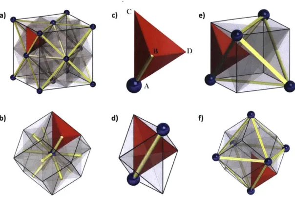
Figure 2.2: Selected decompositions of the FCC geometry. Blue spheres represent the nodes of the lattice, yellow bars represent the links between closest-neighbor nodes. (a) cubic unit-cell, (b) rhombic dodecahedral unit-unit-cell, (c) fundamental tetrahedron, (d) irregular octahedron obtained by collecting all fundamental tetrahedra resting on a midpoint between next-neighbor nodes, (e) cube obtained by collecting all fundamental tetrahedra resting on a tetrahedral site of the lattice, (f) rhombic dodecahedron obtained by collecting all tetrahedra
resting on an octahedral site of the lattice.
* The cubic unit-cell. Figure 2.2a presents a unit-cell of the FCC lattice with the nodes shown in blue, and the line segments joining closest-neighbors shown in yellow. Once the unit-cell of an FCC metamaterial is defined, the periodic lattice is obtained by translations along the edges of the cubic unit-cell. The cubic unit-cell contains four nodes of the FCC lattice (eight eighth-nodes at the unit-cell corners, and six half-nodes on the unit-cell faces).
" The rhombic dodecahedral unit-cell. The Wigner-Seitz cell of the FCC lattice is the simplest volume allowing one to recreate an FCC metamaterial through translations only. It takes the form of a rhombic dodecahedron centered around a single node of the lattice (Fig. 2.2b). As such it is the smallest volume containing all the geometric information necessary for computing the homogenized mechanical behavior of periodic FCC metamaterials.
" The fundamental tetrahedron. Taking into account the full set of FCC symmetries (including rotations and mirror transformations in addition to translations), a tetrahedron can be identified as the fundamental domain defining a periodic FCC metamaterial (Fig. 2.2c). Figures 2.2a and 2.2b show how the fundamental tetrahedron (shown in red) integrates into the cubic and the rhombic dodecahedral unit-cells, respectively. In Fig. 2.2c, the four vertices of the fundamental tetrahedron are identified by letters. Vertex A is the only vertex that is situated at a node of the FCC lattice. Vertex B is located at the mid-point between two first neighbors of the FCC lattice, vertex C is situated at an octahedral site and vertex D lies on a tetrahedral site of the FCC lattice. Using Miller notations to describe the FCC lattice directions, we note that the edges [AB] and [BC] are aligned with the [110] direction, [AC] and [BD] are aligned with the [100] direction, and [AD] and [CD] are aligned with the
[111] direction. The full FCC metamaterial is then obtained as a collection of
copies of this fundamental tetrahedron, each of them translated, mirrored and rotated into a particular configuration.
" Other useful substructures of the FCC lattice are obtained when considering all
fundamental tetrahedra around the vertices B, C and D. The collection of all fundamental tetrahedra around the tetrahedral site D form a cube that features eighth nodes at four of the eight cube corners (Fig. 2.2d). Different from the cubic unit-cell described above, the entire FCC structure cannot be composed through translations only when using the smaller cubic cell obtained from collecting all fundamental tetrahedra around a tetrahedral sites of the FCC lattice. Another rhombic dodecahedral unit-cell is formed by the collection of all fundamental tetrahedra around vertex C (Fig. 2.2e), while an octahedron is formed by all fundamental tetrahedra around vertex B (Fig. 2.2f).
Illustrations of the resulting FCC metamaterials for different motifs included in the fundamental tetrahedron are shown in Fig. 2.3. In the case of struts placed on the edges of the tetrahedron, the widely-studied octet truss (FCC) lattice structure is obtained when positioning a straight strut along the edge [AB] (Fig. 2.3a), or equivalently along edge [BC]
(Fig. 2.3d), while a skeletal rhombic dodecahedron (RD) truss lattice is obtained by selecting the opposing edges ([CD] and [AD], Fig. 2.3f and 2.3c). A simple cubic structure is obtained when positioning a straight strut either along the edge [AC] (Fig. 2.3b) or edge [BD] (Fig. 2.3e). b) irl d) / f) h) )
IL
IL
p
Figure 2.3: Resulting FCC metamaterial architectures for different motifs included in the fundamental tetrahedron: (a) edge AB -* octet-truss, (b) edge AC -+ simple cubic truss, (c) edge AD -- rhombic dodecahedron truss, (d) edge BC -- octet-truss, (e) edge BD -- simple cubic truss, (f) edge CD -+ rhombic dodecahedron truss, (g) surface A -> rhombic dodecahedral foam, (h) surface B -> foam with irregular-octahedral cells, (i) surface C
-rhombic dodecahedral foam, (j) surface D -> simple cubic foam.
2.1.3 Elastic properties
The structures' cubic symmetry imposes constraints on their elastic properties, which are recapped in some details in what follows. The stiffness tensor C of cubic structures has only three independent components C1, C2, C3 . In an orthonormal coordinate system
aligned with the principal axes of symmetry (i.e. parallel to the edges of the cubic unit-cell), the stress-strain relationship can be written as:
-l- -Ell- -C1 C2 C2 0 0 0 -E22 E22 C2 C1 C2 0 0 0 E33 wit33 C2 C2 C1 0 0 0 3 C with C = 2 2(2.1) Y-12 E1 2' 0 0 0 C3 0 0(21 -23 E2 3 0 0 0 0 C3 0 .E13. .E13J -0 0 0 0 0 C3
-where Z ijare the components of the macroscopic stress vector in the natural coordinate system, Ejj are the corresponding macroscopic strain tensor components, and e is a matrix representation of the stiffness tensor. To express remarkable quantities it is preferable to
invert this relation and reason in terms of compliances:
E- -1 S2 S2 0 0 0 E22 E22 S2 S1 S2 0 0 0 E3 3 5 33 with S2 S2 S1 0 0 0 (2.2) E2 120 0 0 S3 0 0 E23 E23 0 0 0 0 S3 0 .E13J LE13J -0 0 0 0 0 S3 Where: S = C2 - C2 = (2.3) (C1 - C2)(2C2 + C1)' (C1 - C2)(2C 2 + C1)' C3
A direct consequence is that traditional measures of stiffness, such as the Young's
modulus or the shear modulus, are direction dependent. Values for important directions, for which Miller indices are used, are given below:
* Bulk modulus:
0 Young's modulus: - Along [100]*: - Along [110]: - Along[ll1]*: = I = (C1 - C2)(C1 + 2C2) C1 + C2 C1(C1 + C2 + C3) -Eno = 2 / (S1 + S2 + S3) = 2 C1(Cl + C2)(2C2)+ C1) C3 (C1 - C2)(2C2 + C1) Ell = 3
/
(Si + 2S2 + 2S3) 3C3(C1 + 2C2) 4C2+ 2C1 + C30 Shear modulus: with non-zero principal stresses along:
- [110]/[110]*: - [100]/[010]*:
G11110 = 1 / (2S3) = C3
/
2G1001010 = 1/(2S, - 2S2) = (C1 - C2)/2
Where the quantities marked with * are extremal. For linear isotropic we have the relationship:
3KE G
9K-E (2.10)
Which provides the isotropy criterion:
Sl- S2 - S3 = 0 (2.11)
It can be rewritten in different manners to obtain different estimates.
S1 - S2 = S3
S1 + 252 + 253
or
3 = S1 (2.12)
The community prefers to estimate the anisotropy of cubic structures using a quantity called the Zener ratio, which corresponds to the ratio of extremal values of the shear modulus: S1 + S _ S3 (2.13) (2.5) (2.6) (2.7) (2.8) (2.9) Gn110i G1001010
Where isotropy corresponds to ' = 1. However one could prefer using the equivalent in terms of Young's modulus:
S1 + 252 + 2S3 _ E100
3S1 (2.14)
3S, Ell,
2.1.4 Other properties
Other properties of the structures than stiffness will in the general case be anisotropic as well, and that even in the event that the elastic isotropy condition is met. However those properties have to respect the cubic symmetry themselves. One interesting case is that of uniaxial properties, such as tensile strength, or even energy absorption in uniaxial compression along one given direction. If one considers a direction as a unit vector in 3D space, one only has to evaluate such a property on a triangle drawn on the unit-sphere, with vertices along one edge of the unit-cell (shorthand [100]), one face diagonal ([110]) and one cube diagonal ([111]). The remaining directional properties can then be deduced from symmetry. The directional dependency of the property can thus be fully described through the use of an inverse pole figure.
2.2.Finite-element Analysis
The mechanical characterization of truss-lattices herein rests mainly on finite-element analysis of the geometries. All finite-element simulations are performed using the commercial software suite Abaqus.
2.2.1 Periodic micro-displacement boundary conditions
In order to describe the behavior of the various structures used herein, we wish to use the vocabulary of continuum mechanics. However the structures are not themselves a continuum as they are heterogeneous, composed of material and void. In this thesis we only resort to a basic application of homogenization theory, for which only an intuitive notion of "averaging" the structure's behavior is needed. The structures considered here are periodic and therefore have an intrinsic length-scale a, which is the side-length of the
unit-cell. The intuitive assumption is that while the structures' behavior remains stable, the deformation field resulting from uniform far-field boundary conditions will respect the periodicity of the lattice, and that no phenomena will develop on larger length-scales. As a result the structure's effective behavior can be deduced from simulations performed on just one unit-cell, which is treated as a representative element volume. In the sequel, such simulations are referred to as "unit-cell simulations".
2.2.2 Implementation in Abaqus/Standard
Periodic micro-displacement boundary conditions are applied in the following manner. With E denoting the macroscopic strain, the local displacement field u is decomposed as
u(x) = i(x) + ii(x) = uO + H. x + R(x) (2.15)
where the macroscopic displacement gradient H is equal to E up to a rotation, U =
uO + H. x is the macro-displacement that corresponds to the applied strain, and i(x) is a
micro-displacement. The unit-cell simulations assume that in the bulk of the material, we have
fi(x + a2ie1) = fi(x) (2.16)
for all integers Ai and all positions x. With a denoting the unit-cell length and ei denoting the principal directions of the lattice, Eq. (10) ensures that the micro-displacement field shares the periodicity of the lattice. The meshes are designed such that for each node
k lying on first face of the unit-cell there exists a node I on the opposite face with normal
vector n, with the initial position vectors respecting the relations x, = Xk + a -n. The difference in displacements then reads:
ul(xi) - U(Xk) = i(Xk + an) - i(Xk) + ii(Xk + an) - ii(Xk) = aH.n (2.17)
The periodicity of micro-displacements is enforced by kinematically constraining the difference in the displacements of paired nodes, and setting this difference as equal to the displacement deduced from the macroscopic strain: u1 - Uk = aH -n. Three dummy
correspond to the components of the displacement gradient H. Kinematic constraints on the dummy nodes are used to enforce the symmetry of this tensor and make it equal to the macroscopic small strain tensor E. As a result, the forces applied to the dummy nodes correspond to the components of the Piola stress tensor P. In practice, an additional layer of dummy nodes, with their degrees of freedom kinematically linked to that of the initial layer through linear equations corresponding to the associated rotation matrix, is used to easily change the loading orientation.
2.2.3 Implementation in Abaqus/Explicit
The previous paragraph refers to the implementation of periodic boundary conditions in the implicit solver Abaqus/Standard. However there are cases for which the use of an explicit scheme is preferable: in the case of large models for which large amounts of memory are needed, or for example in the presence of instabilities that provoke a rupture of symmetry, which can lead to non-convergence of the implicit solution. Unfortunately Abaqus/Explicit does not accept large numbers of inter-connected kinematic constraints in the form introduced above, where all surface nodes are interconnected to just three dummy nodes. To resolve this difficulty, a different dummy node is used for every pair of surface nodes. This modification is made at a price, as the ability to control the Piola stress tensor is lost. Such simulations therefore include no stress-free boundary conditions, and are completely strain-led.
2.2.4 Multi-cell specimens
2.2.4.1 Motivation
As explained above, periodic micro-displacement boundary conditions are only realistic if the structure's response does not include features of larger length-scale than that of the unit-cell. However this is an unrealistic assumption in a number of cases.
One of them involves uniaxial compression of structures of relative density sufficiently low (typically p ; 0.1 ), for which the stress response obtained through unit-cell simulations will feature a local maximum followed by a phase of softening. Ultimately the
geometry will be compressed enough for internal contact to be initiated and the unit-cell will harden again when compaction occurs. In this case once again, localization will occur in one plane of unit-cells. Once the unit-cells of this plane harden again, another plane starts to localize. In practice the compaction of one plane changes the boundary conditions on the neighboring planes and lowers the force necessary to compact them. What follows in the case of a perfect geometry (and in simulations) is a compaction regime marked by a first peak in stress, followed by lower peaks, revolving around a plateau value. In actual experiments, defects in the specimens lead to an averaging-out of the response which materializes by a stress plateau, much similar to the behavior observed on foams (e.g. Mohr and Doyoyo 2004). Such behavior will be observed during experimental testing of low relative density structures, see for example Fig. 3.15, where a P = 0.2 octet-truss develops compaction zones in the form of shear bands, reflected in the associated stress-strain curves
by stress oscillations around a stress plateau.
This behavior, including the level of the stress plateau, cannot be captured by unit-cell simulations which typically have only one layer (and thus only the first peak). To remedy this, larger samples consisting in stacks of several unit-cells are used. Multi-cell simulations are typically realized using Abaqus/Explicit, because of both the large number of elements and the prevalence of contact. Figure 2.4 presents an example for an octet-truss with # = 0.1, comparing the results of a unit-cell simulation under uniaxial compression
and a multi-cell simulation consisting in a cubic block of three unit-cells in side under compression between two platens. While the two simulations agree up to the observed first peak in stress, the unit-cell shows strain-softening up to the maximum investigated engineering strain of 0.6. The multi-cell simulation shows multiple peaks corresponding to the successive crushing of the different layers. It is interesting to note the local minima observed do not correspond to the minimum post-peak stress observed for the unit-cell, highlighting the necessity of such an approach.
a 40 4 30 20 10 -Unit-Cell -Multi-Cell 01 0 0.2 0.4 0.6 Engineering strain [-] EVP 0 0.2 0.4
Figure 2.4: Numerical results of the uniaxial compression along [100] of an octet-truss of relative density 10%. a) Comparison of stress-strain curves obtained with unit-cell, and multi-cell simulations. b) Deformation pattern and partial equivalent plastic strain distribution on a multi-cell simulation at engineering strain 0.3. c) Deformation pattern and equivalent plastic strain distribution on a unit-cell simulation at engineering strain 0.3.
2.2.4.2 Oriented multi-cell specimens
To evaluate the large strain response of the metamaterial structures along these three directions, we consider three distinct multi-cell specimens that feature the same shell structure, but with different lattice orientations with respect to the specimen edges (and hence the directions of loading). They are generated from three different parallelepipedic unit-cells whose face normals are given by the following sets of orthonormal vectors.