Rational Design of Mesoporous Materials with
Core/Shell Structures with Applications for
Sustainability
Thèse
Zhen Kun Sun
Doctorat en génie chimique
Philosophiae Doctor (Ph.D.)
Qué bec, Canada
© Zhen Kun Sun, 2015
Résumé
Les matériaux mésoporeux sont devenus des nanomatériaux d’une grande importance, et le contrôle des structures des matériaux mésoporeux est essentiel pour une variété d'applications pratiques. Les matériaux «cœur/coquille» structurés sont un type de matériaux hybrides qui non seulement possèdent les propriétés des composants individuels, mais présentent également de effets synergiques entre le «cœur» et la «coquille». La conception de matériaux mésoporeux et «cœur/coquille» structurés pour les appliquer avec succès dans la pratique devrait être une force de progrès importante pour le développement continu. Cette thèse se concentre principalement sur deux aspects: (1) une conception de matériaux mésoporeux «cœur/coquille» structurés en vue de résoudre les problèmes de synthèse, qui entravent leurs nouvelles applications et (2) l'application de matériaux mésoporeux dans la capture du CO2 cyclique pour améliorer la durabilité des sorbants de
CO2 en prenant avantage du concept de «cœur/coquille».
Visant le cyclage de l’hydroxyde de calcium, une technologie attrayante pour la capture du CO2 à grande échelle, nous avons établi un nouveau mésoporeux
«cœur/coquille» structuré à base de CaO qui présentait une grande stabilité et d'excellentes performances de résistance à l’attrition, attribuées aux avantages des matériaux mésoporeux et à la configuration de «cœur/coquille». Notre procédé de fabrication peut être facilement réalisé à grande échelle et répond aux exigences de la circulation entre des réacteurs en lit fluidisé.
Les nanoparticules métalliques ont normalement tendance à se coaguler ensemble dans des réactions catalytiques, et sont difficiles à séparer. Par conséquent, nous avons démontré une synthèse de microsphères Fe3O4@C-Pd@mSiO2 à composants multiples et
catalytiques de Pd confinées, et ayant des canaux mésoporeux ordonnés et facilement accessibles.
Récemment, des méthodes diverses ont été proposées pour fabriquer un revêtement de matériaux mésoporeux sur un cœur par un processus de «soft-templating». Cependant, les diamètres des mésopores générés sont généralement très faibles (< 3 nm), ce qui peut limiter leurs nouvelles applications. Ici, nous avons réalisé la synthèse de microsphères «cœur/coquille» structurées superparamagnétiques possédant une coquille externe de silice mésoporeuse ordonnée à larges pores (4,5 nm), en adoptant un copolymère tribloc comme agent tensioactif directeur de structure.
Abstract
Mesoporous materials, especially ordered ones have become ones of great importance nanomaterials, which possess regular, uniform and interpenetrating mesopores in nanoscale. Morphology and texture controls towards mesoporous materials are critical for a variety of practical applications, the ultimate goal of which are the realization of their functional design. Core/shell composite materials are a type of functional hybrid materials which not only possess the properties of the individual components, but also exhibit some new or synergistic effects between the core and the shell. The design of mesoporous materials with unique core/shell configuration and multifunctions to make them successfully applied in practice, should be an important driving force for the continuous development of current material science. This thesis mainly focuses on two aspects: (1) careful design of core/shell structured mesoporous materials in order to solve the problem and difficulty in synthesis, which hinders their further applications and (2) application of mesoporous materials in cyclic CO2 capture to enhance the durability of CO2 sorbents by taking advantage of the
core/shell concept.
Aiming at the calcium looping cycle, an attractive technology for large-scale CO2
capture, we have prepared novel mesoporous core/shell structured CaO-based sorbents which exhibit highly stable cyclability and excellent attrition-resistance performances, attributed to advantages of both mesoporous materials and unique core/shell configuration. Our fabrication method could easily be realized in large-scale and meet the requirements of circulating fluidized bed reactors.
Owing to their high surface energies, metallic nanoparticles normally tend to aggregate together during catalytic reactions, and their separation from a complex heterogeneous system is another obstacle. In this regards, we have demonstrated a facile and versatile synthesis of multicomponent and multifunctional microspheres Fe3O4
@C-Pd@mSiO2 with well-defined core/shell structures, confined catalytic Pd nanoparticles and
accessible ordered mesopore channels.
Recently, various methods have been proposed for coating mesoporous shells on cores by soft-templating process. However, the generated mesopores are usually very small (< 3 nm), which may limit their further applications. In this work, we have accomplished the synthesis of superparamagnetic core/shell structured microspheres possessing an outer shell of ordered mesoporous silica with large pores (4.5 nm) by adopting triblock-copolymer Pluronic P123 as soft-template.
Table of Contents
Résumé ... III Abstract ... V Table of Contents ... VII Abbreviations ... XIII Index of Tables ... XIX Index of Figures ... XXI Acknowledgments ... XXIX Foreword ... XXXI
Chapter 1 Introduction ... 1
1.1 General Introduction ... 1
1.2 Objectives of this thesis ... 3
1.3 References ... 5
Chapter 2 Mesoporous Materials: Synthesis Strategies, Morphology Control and Applications ... 7
2.1 Mesoporous Materials ... 7
2.2 Synthesis of Mesoporous Materials ... 9
2.3 Chemical Composition of Mesoporous Materials ... 10
2.4 Mesoporous Materials with Different Morphologies ... 13
2.4.1 Tuning Morphologies of Mesopores at Micro-Scale ... 13
2.4.2 Variation of Morphologies of Materials at Macro-Scale ... 16
2.4.3 Mesoporous Thin Films ... 17
2.4.3.1 Silica-based mesoporous thin films ... 17
2.4.3.2 Mesoporous thin films with other compositions ... 20
2.4.4 Monolithic Mesoporous Materials ... 24
2.4.4.1 Monoliths with simplex mesopores ... 25
2.4.4.2 Mesoporous monoliths with hierarchical porous structures ... 26
2.4.4.3 Functionalized mesoporous monoliths ... 30
2.4.5 Mesoporous Single-Crystals or Monocrystals ... 32
2.4.5.2 Mesoporous single-crystals with other compositions ... 35
2.4.6 Mesoporous Materials of Nanofibers ... 37
2.4.6.1 Applications of mesoporous nanofibers ... 37
2.4.6.2 Synthetic strategies for mesoporous nanofibers ... 38
2.4.7 Rod-Like Mesoporous Materials ... 42
2.4.7.1 Silica-based rod-like mesoporous materials ... 42
2.4.7.2 Carbon-based mesoporous nanorods ... 45
2.4.7.3 Mesoporous metal oxide nanorods ... 46
2.4.8 Mesoporous Microspheres ... 48
2.4.8.1 Plain mesoporous microspheres ... 51
2.4.8.2 Hollow mesoporous microspheres ... 59
2.4.8.3 Mesoporous vesiculars microspheres ... 62
2.4.9 Core/shell structured mesoporous materials ... 66
2.5 References: ... 68
Chapter 3 Core/Shell Structured Mesoporous Materials ... 87
3.1 Core/shell Nanomaterials ... 87
3.2 Core/Shell Mesoporous Materials ... 90
3.3 Mechanisms and Synthesis Routes for Core/Shell Structured Mesoporous Materials ... 91
3.3.1 Core/shell Structured Mesoporous Materials Prepared by Stöber Method .. ... 95
3.3.1.1 Disordered Mesopores Generated by the Stöber Method ... 96
3.3.1.2 Ordered Mesopores Generated by the Stöber Method ... 99
3.3.1.3 Modified Stöber Method for Mesoporous TiO2 Coating ... 101
3.3.1.4 Yolk/shell Structures with mesoporous cores or shells ... 103
3.3.2 Microemulsion Pathway for Core/shell Structured Mesoporous Materials . ... 105
3.3.3 Core/shell Structured Mesoporous Materials Generated in Confined Space ... 108
3.3.4 Spray-Drying Techniques ... 109
3.4 Applications of Core/Shell Structured Mesoporous Materials ... 111
3.4.1 Applications in Catalysis ... 111
3.4.3 Energy Storage and Conversion ... 116
3.5 References ... 119
Chapter 4 A Facile Fabrication of Mesoporous Core-Shell CaO-Based Pellets with Enhanced Reactive Stability and Resistance to Attrition in Cyclic CO2 Capture ... 127
4.1 Overview of CO2 and Its Impact on Greenhouse Effect ... 129
4.2 Carbon Capture and Storage (CCS) ... 130
4.3 Strategies for CO2 Capture or Separation ... 133
4.3.1 Physical and Physicochemical Hybrid Absorption ... 133
4.3.2 Chemical Absorption ... 135
4.4 Calcium Based Sorbents ... 139
4.4.1 Reactivation of Sintered sorbents by Hydration ... 142
4.4.2 High Temperature Pre-treatment ... 143
4.4.3 Doping ... 144
4.4.4 Other Modifications ... 145
4.5 Our strategies for improving the performance of calcium based sorbents .... 146
4.6 Experimental details ... 148
4.6.1 Chemicals and materials ... 148
4.6.2 Cadomin CaO based pellets ... 149
4.6.3 Mesoporous SiO2/ZrO2 shelled core/shell pellets ... 149
4.6.4 Core/shell pellets with mesoporous ZrO2 shell ... 151
4.6.5 Cyclic CO2 capture ... 151
4.6.6 Attrition tests ... 151
4.6.7 Characterization and measurements ... 153
4.7 Results and discussion ... 154
4.7.1 Characteristics of the sorbents ... 154
4.7.2 Performances of sorbents during cyclic CO2 capture ... 158
4.7.3 Understanding the processes ... 165
4.7.4 Attrition ... 170
4.8 Conclusions ... 172
4.9 References ... 174
Chapter 5 A versatile designed synthesis of magnetically separable nano-catalysts with well-defined core–shell nanostructures ... 181
5.1 Brief introduction ... 183
5.2 Our strategies ... 184
5.3 Experimental details ... 186
5.3.1 Chemicals and materials ... 186
5.3.2 Synthesis of Fe3O4 particles ... 186
5.3.3 Synthesis of Fe3O4@C microspheres ... 186
5.3.4 Deposition of Pd (or Pt) nanoparticles on Fe3O4@C microspheres ... 187
5.3.5 Synthesis of Fe3O4@C@Pd@mSiO2 Microspheres ... 187
5.3.6 Suzuki-Miyaura Cross-coupling Reactions ... 188
5.3.7 Measurements and characterizations ... 188
5.4 Results and discussion ... 189
5.4.1 Characteristics of the sorbents ... 189
5.4.2 Understanding the processes ... 196
5.4.3 Catalytic performance ... 197
5.5 Conclusions ... 199
5.6 References ... 201
Chapter 6 Superparamagnetic Core/Shell Structured Mesoporous Microspheres with Large Pore Sizes ... 203
6.1 Brief introduction ... 205
6.2 Our strategies ... 206
6.3 Experimental details ... 208
6.3.1 Chemicals and materials ... 208
6.3.2 Synthesis of Fe3O4 Particles ... 208
6.3.3 Synthesis of Fe-nS Microspheres ... 209
6.3.4 Synthesis of Fe-nS-mS Microspheres ... 209
6.3.5 Removal of MC-LR in Water Using Fe-nS-mS Microspheres ... 210
6.3.6 Characterization and Measurements ... 210
6.4 Results and discussion ... 211
6.4.1 Characteristics of Fe-nS-mS Microspheres ... 211
6.4.2 Varying the thickness of mesoporous silica shells ... 215
6.4.3 Magnetic Removal of Toxic Microcystin from Water Using Fe-nS-mS Microspheres ... 217
6.5 Conclusions ... 221
6.6 References ... 223
Chapter 7 Conclusions and Prospects ... 225
7.1 General conclusions ... 225
7.2 Prospects ... 228
Chapter 8 Scientific Contributions ... 231
8.1 Publications ... 231
Abbreviations
1-, 2- or 3-D 1-, 2- or 3-Dimensional
3-CPAHCl 3-chloropropylamine-hydrochloride 3DOMs Three-dimensionally ordered macroporous
ACN Acetonitrile
AEAEAP-TMS 3-[2-(2-aminoethylamino) ethylamino] propyltrimethoxysilane AEAP-TMS [3-(2-aminoethylamino) propyl] trimethoxysilane
AP-TMS 3-Aminopropyltrimethoxysilane APTMS Aminopropyltrimethoxy silane
ASTM American Society for Testing and Materials B50–6600 PEO39PBO47PEO39
BCPs Behavior of Block Copolymers
BET Brunauer–Emmett–Teller
BJH Barrett-Joyner-Halenda Brij 58 C16H33PEO20
BTEE 1, 2-bis(triethoxysilyl) ethane BTME 1, 2-bis(trimethoxysilyl) ethane BVDV Bovine viral diarrhoea virus C18-3-1 C18H37N(CH3)2(CH2)3N(CH3)3Br2
C18TAC Octadecyltrimethylammonium chloride
C18TMS n-Octadecyltrimethoxysilane
CASH Combined Assembly by Soft and Hard CCS Carbon Capture and Sequestration
CFB Circulating Fluidized Beds CHCA α-Cyano-4-hydroxycinnamic acid
CL Cadomin limestone
CMC Critical Micelle Concentration
CNTs Carbon nanotubes
Cou4 Coumarin4, an organic dye
CP Cadomin pellets
CSA Cooperative Self-Assembly CTA+ Cetyltrimethylammonium
CTAB Cetyltrimethylammonium bromide CTAC, C16TAC Cetyltrimethylammonium chloride
CTEABr C16H33N(C2H5)3Br
CVD Chemical Vapor Deposition
DEA Diethanolamine
DMFC Direct Methanol Fuel Cell
DOX Doxorubicin
EC Electrochemical
EDLC Electrochemical Doubly-Layered Capacitor EDX Energy-Dispersive X-ray
EG Ethylene glycol
EISA Evaporation Induced Self-Assembly F108 PEO132.6PPO50.3PEO132.6
F127 PEO106PPO70PEO106
FC4 [C3F7O(CF(CF3)CF2O)2CF-(CF3)CONH(CH2)3N+(C2H5)2CH3]I
FE-SEM Field-Emission Scanning Electron Microscope
GHG Greenhouse Gases
HPLC High Performance Liquid Chromatography
HyPr-Ring Hydrogen Production by Reaction-Integrated Novel Gasification ICP-AES Inductively Coupled Plasma Atomic Emission Spectrometry Igepa® CO-520 Polyoxyethylene (5) nonylphenylether, branched
IPCC International Panel on Climate Change
iPrOH Isopropanol
ITO Indium tin oxide
IUPAC International Union of Pure and Applied Chemistry KLE Poly(ethylene-co-butylene)-block-poly(ethylene oxide) L121 PEO4PPO60PEO4
LEGS Lime-Enhanced Gasification of Solid Fuels MALDI Matrix-Assisted Laser Desorption/Ionization
MALDI-TOF MS Matrix-Assisted Laser Desorption/Ionization Time-of-Flight Mass Spectrometry
MBE Molecular Beam Epitaxy MCF-7 Human breast cancer cells
MC-LR Microcystin-LR
MDEA Methyldiethanolamine
MEA Monoethanolamine
MMDR Mass-Mean Diameter Reduction MOFs Metal–organic frameworks MRI Magnetic Resonance Imaging MWCNT Multi-walled carbon nanotube
NaAc sodium acetate
NF Nonwoven fabrics
NGCC Natural Gas Combined Cycle NIH-3T3 Mouse embryonic fibroblast cells
ODA Octadecylamine
P123 PEO20PPO70PEO20
PC Polycarbonate
PDMS Polydimethylsiloxane PEG Poly(ethylene glycol) PEO Poly-(ethylene oxide)
PEO–PPO–PEO Poly(ethylene oxide)–poly(propylene oxide)–poly-(ethylene oxide) PFOA Perfluorooctanoic acid
pI Isoelectric Point
PI-b-PEO Poly(ethylene oxide)-block-polyisoprene
PL Photoluminescence
PMMA Poly(methyl methacrylate)
PMO Periodic mesoporous organosilica
PS Polystyrene
PSD Particle Size Distribution
PS-P4VP Polystyrene-block-poly(4-vinylpyridine) PU Polyurethane PVP Polyvinylpyrrolidone QDs Quantum dots RF Resorcinol–formaldehyde S/N Signal-to-Noise
SAED Selected Area Electron Diffraction SAXS Small-Sngle X-ray Scattering SBET Specific surface area
SiPC Silicon phthalocyanine dichloride
SQUID Superconductive Quantum Interference Device SWCNTs Single-walled carbon nanotubes
Synperonic® NP-5 Nonylphenol with 10 and 15 mol of EO
TBOT Tetrabutyl titanate TBZ Tetrabutyl ziconate
TEA Triethanolamine
TEM Transmission Electron Micrographs TEOA Triethyl orthoacetate
TEOS Tetraethyl orthosilicate TEPA Tetraethylenepentamine TFA Trifluoroacetic acid
TFGS Thermal Analysis Gas Station TGA Thermogravimetric Analyzer
THE Tetrahydrofiiran
TMB Trimethylbenzene, mesitylene TMOS Tetramethoxysilane
Triton X-100 Polyoxyethylene tert-octylphenyl ether TTIP Titanium tetraisopropoxide
XRD X-ray Diffraction
Index of Tables
Table 2.1 Types of porous materials and some examples ... 7
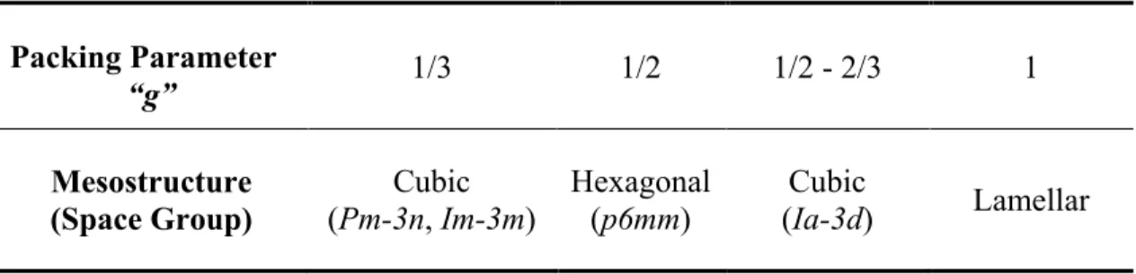
Table 2.2 Mesophases as a function of the packing parameter “g” ... 14
Table 4.1 The general CO2 adsorption capacities of the main types of adsorbents ... 138
Table 4.2 Elemental composition (wt %) ... 149
Table 4.3 Elemental composition of each sorbent (wt %) ... 157
Table 4.4 CO2 uptakes, conversion, and loss of activity after the 1st and 20th carbonation– decarbonation cycle based on total mass of decarbonated sorbent ... 162
Table 4.5 CO2 uptakes, conversion, and loss of activity after the 1st and 20th carbonation– decarbonation cycle based on total mass of calcium. ... 163
Table 4.6 Porous properties of each sorbent before and after 20 decarbonation-carbonation cycles ... 167
Table 5.1 Results of Suzuki-Miyaura cross-coupling reactions ... 198
Table 6.1 Structure parameters of the samples synthesized with different amounts of TEOS. ... 216
Index of Figures
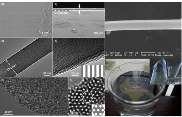
Figure 2.1 Mesoprous materials of M41s family: structural models of M41s (top) and TEM images (bottom) of the final materials ... 8 Figure 2.2 Scheme of two representative synthesis routes for ordered mesoporous materials: (a) soft-templating method and (b) hard-templating (nanocasting) method ... 9 Figure 2.3 SEM and TEM images of mesoporous silicas SBA-15 (A), KIT-6 (B) and SBA-6 ... 10 Figure 2.4 Models of mesopores with different mesostructures and symmetries: (A) p6mm, (B) Ia-3d, (C) Pm-3n, (D) Im-3m, (E) Fd-3m and (F) Fm-3m ... 15 Figure 2.5 SEM images (A and C) and TEM image (B) of free-standing mesoporous silica film ... 18 Figure 2.6 Mesoporous silica thin films with ordered perpendicular mesopore channels by a sol-gel approach ... 20 Figure 2.7 The synthetic procedure of mesoporous carbon thin film by using mesoporous silica film as template (A), the synthesis protocol used to prepare well-defined carbon nanostructures by the solvent annealing route based on the self-assembly of block copolymers (B) and preparation process for free-standing mesoporous carbon thin films with highly ordered Fmmm mesostructure by using a coating-etching approach (C) ... 22 Figure 2.8 Optical images of silica/block copolymer F127 monolith composite (A), silica/ block copolymer P123 monolith synthesized by liquid-paraffin-medium protected solvent evaporation (B), the monolith in image B doped with different metal ions, which is colorless for pure silica sample, pink for Co2+
doped one, yellow for Fe3+ doped one and green for Cu2+ doped one (C, from left to right) and monolith in image B after calcination (D) ... 25 Figure 2.9 Hierarchical porous silica synthesized by using PEG (A), polyacrylamide hydrogel in the presence of electric field (B) and PS foam (C) to generate macropores ... 27 Figure 2.10 (A) The strategy for the preparation of 3DOM structure by using preformed colloidal crystals as templates which is infiltrated with precursor material (mesoporous synthetic precursor for mesoporous materials). The ordered macropores were formed after the removal of these templates. (B) 3DOM of mesoporous silicas and (C) carbons ... 29 Figure 2.11 Optical images of diamine-grafted monolith mesoporous silica monolith (A) and amine-containing monolithic mesoporous silica (B), and TEM images of Co-based nanoparticles incorporated mesoporous silica monolith (C) ... 31
Figure 2.12 Mesoporous silica single-crystals of MCM-48 (A) and SBA-1 (B) prepared using anionic surfactant as mesostructure directing agent, and silica single-crystal synthesized by nonionic surfactant (C) ... 33 Figure 2.13 SEM and TEM images and XRD patterns of mesostructured blue molybdenum oxides single-crystals with different shapes (A), mesoporous carbon single-crystals (B) and the proposed formation mechanism of mesoporous carbon single-crystals ... 36 Figure 2.14 (A) TEM images at high- and Low-magnification of mesoporous nanofibers containing ellipsoidal gold nanoparticles, (B) STEM-HAADF and TEM images of mesoporous carbon nanofibers and the corresponding image of fast Fourier transforms of the entire areas indicating the high order of the mesostructure and (C) Optical photographs of dye-polluted water before and after adsorption by the mesoporous carbon fibers, and TEM and SEM images of the corresponding absorbents ... 37 Figure 2.15 (A) SEM images at different magnifications of spun mesoporous silica fibers prepared by using CTAB as surfactant after calcination and (B) mesoporous fibers synthesized by a dip-withdraw method using nonionic surfactants ... 39 Figure 2.16 TEM and SEM images of mesoporous silica fibers prepared by electrospun (A) and mesoporous titania fibers synthesized by electrospun (B) ... 41 Figure 2.17 TEM images of mesoporous silica nanorods MSU-4 prepared by using nonionic PEO-based surfactants Tween 60 and Pluronic P123 in the presence of inorganic salt NaF (A), highly ordered mesoporous silica SBA-15 nanorods (B) and Monodispersed SBA-15 rods with different lengths (C) ... 42 Figure 2.18 Ordered chiral mesoporous silica rods prepared by using chiral anionic surfactants (A), achiral surfactants (B) and co-surfactant system (C) ... 44 Figure 2.19 Schematic diagrams for the synthesis of mesoporous TiO2 nanorods by using
a sonochemical method ... 46 Figure 2.20 SEM and TEM images of mesoporous nanorods of Fe3O4 (A), TiO2 (B), In2O3
(C) and Pt ... 47 Figure 2.21 Schematic representation of the mesoporous silica microspheres used as transmembrane protein carrier (A), Monodispersed colloidal spheres self-organizing into an ordered structure of colloidal crystal film (B) and TEM images of mesoporous silica microspheres loaded with Au nanoparticles and yolk-shell microspheres with the core of the Au nanoparticle, applied for catalysis (C) ... 49 Figure 2.22 Schematic illustration of the release process of azobenzenederived surfactant from the silica framework in water/ethanol (v/v = 3:1) at 60 °C under UV light (A), Stöber-kind mesoporous microspheres with different particle sizes (B) and with functionalization of sulfonic acid groups (C) ... 52
Figure 2.23 SEM (A-C and J-L) and TEM (D-F and G-I) images of Stöber-kind mesoporous silica microspheres prepared by using cetyltrimethylammonium (CTA+) as the templating surfactant and small organic amines of triethanolamine, 2-amino-2-(hydroxymethyl)propane-1,3-diol and triethyleneamine as the mineralizing agent, respectively (A-F) and mesoporous silica microspheres prepared in a heterogeneous oil−water biphase stratification reaction system (G-L) ... 54 Figure 2.24 Disordered (A) and ordered (B) mesoporous carbon microspheres prepared by using aerosols with the help of a spray dryer ... 57 Figure 2.25 Ordered mesoporous carbon microspheres synthesized by hydrothermal method (A) and confined coassembly process using 3-D-ordered macroporous silica as the template (B) ... 58 Figure 2.26 Mesoporous silica hollow microspheres prepared by using hematite nanoparticles as templates ... 60 Figure 2.27 Mesoporous silica hollow microspheres prepared by sol-gel/emulsion technology (A) and water incubation method (B) ... 61 Figure 2.28 Schematic representation and the TEM images of the siliceous vesicles and silica foam after structural transformation when the ionic strength changed (A) and multilamellar vesicles obtained by using P123 and PFOA as cotemplates in an acid-catalyzed sol-gel process (B) ... 63 Figure 2.29 (A) Mesoporous siliceous vesicles with controllable shapes prepared by adjusting the hydrophilic/hydrophobic ratios of mixed block copolymer templates between PEO39PBO47PEO39 and PEO34PBO11PEO34, (B) Ultrasmall,
well-dispersed mesoporous silica vesicles with accessible cavity synthesized by using block copolymer Pluronic F108 as the template and TEOS as a silica source under acidic conditions and (C) two-step synthesis approach to fabricate mesoporous silica vesicles with a uniform particle size of around 50 nm, a wall thickness of 6 nm, cavities of 40 nm and tunable entrance size ... ... 64 Figure 3.1 Publications per year concerning “core/shell” during the period from 2005 to the November 2014 (Data collected from “Web of ScienceTM database”
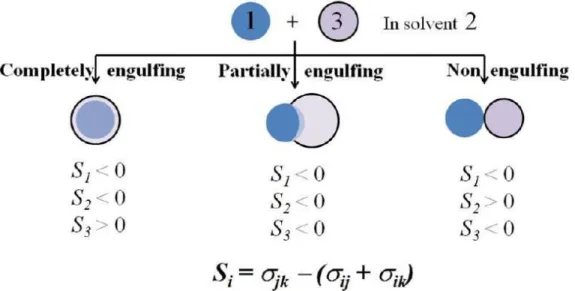
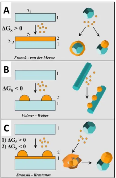
refined by keywords “core/shell, core-shell or core@shell” in titles). ... 88 Figure 3.2 Core/shell nanostructured materials with different shapes of (A) spherical core/shell material, (B) movable core within hollow shell material (named yolk-shell or rattle-type structures), (C) core/shell material with multishells, (D) multiple small core materials coated by single shell, (E) core/shell nanorod and (F) cubic core/shell material. ... 89 Figure 3.3 Equilibrium configurations for two immiscible liquid droplets 1 and 3 in solvent 2 ... 92 Figure 3.4 Comparative scheme illustrating possible heterogeneous deposition modes for a secondary material (referred to as “2”) that is deposited from the respective
molecular precursors onto a preformed seed substrate of a different material (referred to as “1”): (A) Franck – van der Merwe; (B) Volmer – Weber; and (C) Stranski – Krastanov regimes ... 93 Figure 3.5 Illustration and TEM images of synthesis of core/shell nanospheres with a core of magnetite particles and a shell of mesoporous silica (A), a rattle-type hollow magnetic mesoporous sphere obtained after these core/shell nanospheres were treated by a hydrothermal process (B) and monodisperse nanospheres with cores of magnetite (Fe3O4) nanocrystals and CdSe/ZnS
quantum dots embedded simultaneously in mesoporous silica shell (C) ... 96 Figure 3.6 Schematic illustration of the concept of “surface-protected etching” for transforming solid silica spheres into permeable shells and TEM images showing the morphology of PVP-treated SiO2 particles after etching by NaOH
for 0 h, 1 h, 2 h45 min and 3 h, respectively (A), and TEM images of Fe3O4/SiO2/Au/porous-SiO2 composite colloids collected after different
periods of etching (B) ... 98 Figure 3.7 Synthesis scheme of Fe3O4@nonporous-SiO2@mesoporous-SiO2
microspheres and their corresponding low-angle XRD pattern, SEM and TEM images (A), and TEM images of the Fe3O4@nonporous-SiO2@Au
nanoparticles@mesoporous-SiO2 microspheres with an 90 nm thick
mesoporous silica layer (B) ... 100 Figure 3.8 SEM and TEM images and energy-dispersive X-ray spectroscopy spectrum (taken from the center of a single core/shell particle) of synthesized hematite/TiO2 mesoporous core/shell particles ... 101
Figure 3.9 SEM and TEM images of core/shell α-Fe2O3@TiO2 mesoporous
microellipsoids prepared by the kinetics-controlled coating method ... 102 Figure 3.10 Procedure for the preparation of yolk–shell structures with a mesoporous shell, and SEM and TEM images of yolk/shell material synthesized using silica spheres with 260 nm as core ... 104 Figure 3.11 Yolk/shell structured mesoporous inorganic–organic hybrid microspheres prepared through water incubation ... 105 Figure 3.12 Schematic representation of the incorporation mechanism of hydrophobic QDs (in orange) into silica spheres by the reverse microemulsion method. (a) Illustrates the octadecylamine (ODA) coated QDs dispersed in cyclohexane. Upon addition of TEOS or Igepa® CO-520, ODA is largely replaced, resulting
in TEOS (b1) or Synperonic® NP-5 (b2) coated QDs. When subsequently Igepal CO-520 or TEOS is added, equilibrium is reached again (c), where the QDs are coated by (hydrolyzed) TEOS and surfactant. Upon addition of ammonia, TEOS is further hydrolyzed, and replaces all Igepal® CO-520 (d). Water and ammonia molecules are present in between the TEOS-coated QD and the surfactant aggregates ... 106
Figure 3.13 Nanospheres of Fe3O4 (A) and Au nanoparticles (B) encapsulated in porous
silica shells prepared by w/o microemulsion system ... 107 Figure 3.14 Core/shell structured ordered mesoporous carbon microspheres supported Co/CoxOy nanoparticles (A) and synthetic diagram of core/shell structured mesoporous composites of uniform and discrete microspheres with magnetic cores and mesoporous silica shells (B) ... 108 Figure 3.15 Schematic of the aerosol process used to synthesize spherical mesoporous carbon particles (A) and SEM and TEM images of core/shell structured silica-based mesoporous microspheres encapsulating magnetic nanoparticles synthesized by an aerosol-assisted route with the help of the spray-drying technique (B) ... 110 Figure 3.16 Scheme of the synthetic process and TEM images of Au@ZrO2 core/shell
nanocatalysts (A), thermal stability of Pt@mSiO2 nanospheres after
calcination at 350 °C, 550 °C and 750 °C respectively (B), and Au@TiO2
yolk/shell nanostructured catalysts (C) ... 111 Figure 3.17 Catalysts of Fe3O4@ thiol-mesoporous silica@Au microspheres and their
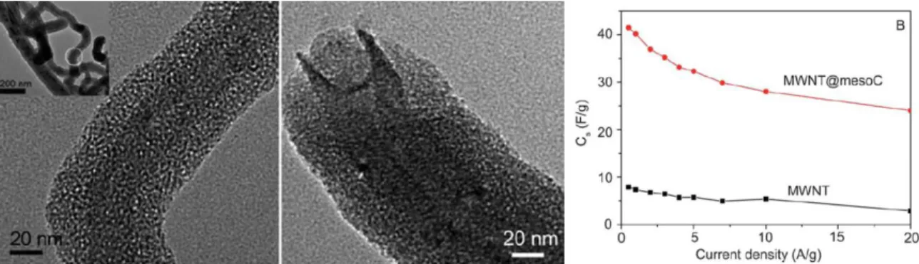
magnetic properties ... 113 Figure 3.18 Core/shell nanospheres with iron oxide nanoparticles incorporated within the mesoporous silica shells and fluorescence microscopy images of these nanoparticle uptake by human pancreatic cancer cells PANC-1 and BxPC3 ... ... 114 Figure 3.19 Rattle-like dual-pore mesoporous carbon@silica hybrid nanospheres and their applications for effective inhibition of human ovarian cancer cells and killing drug-resistant cells ... 115 Figure 3.20 MWNT@mesoS composite prepared by a sol–gel coating pathway using CTAB as a template showing uniform core/shell structure with shell thickness of 20 nm and interpenetrated mesoporous networks, and the specific capacitance as a function of current density of the pristine MWNTs and MWNT@mesoC electrode materials in 1.0 M (C2H5)4NBF4/PC electrolyte...
... 116 Figure 3.21 TEM images of mesoporous SnO2/C particles and their multirate tests as
anode material for lithium-ion batteries (A), and core/shell structured Si nanoparticles@TiO2-x/C mesoporous microfiber composite (B) ... 117
Figure 4.1 Three CO2 capture processes: post-combustion, pre-combustion and
oxy-combustion ... 132 Figure 4.2 Schematic of dual-fluidized bed sorbent looping facility ... 139 Figure 4.3 The formation process of the core/shell structured CaO based pellets using the general repeated impregnation-evaporation coating process. ... 150 Figure 4.4 Schematic diagram of the air-jet attrition test unit ... 152
Figure 4.5 SEM images at different magnifications (500x or 100kx) taken on the surface of sorbents: CP (1a and b); CSP@Si/Zr (1c and d); and CSP@Zr (1e and f) after 4 impregnation-evaporation process cycle. ... 154 Figure 4.6 SEM images taken on cross-sections of samples CSP@Si/Zr (a and c) and CSP@Zr (b) after the 4th (a, b) or 6th (c) impregnation-evaporation coating cycles. ... 155 Figure 4.7 EDX mapping images for elements Si (green dots), Zr (red dots) and Ca (blue dots and violet dots) of samples CP (Figure a), CSP@Si/Zr (Figures b and c) and CSP@Zr (Figures. d and e) after 4 (b and d) and 6 times (c and e) impregnation coating with their corresponding SEM images (first vertical column) ... 156 Figure 4.8 The wide-angle XRD patterns of sample CP (left) and core/shell one CSP@Zr-6 (right)... 158 Figure 4.9 Weight change of samples CP, CSP@Si/Zr (after 4 coating cycles) and CSP@Zr (after 4 coating cycles) during 20 carbonation-decarbonation cycles. ... 158 Figure 4.10 The ultimate CO2 uptake capacity of the natural derived Cadomin limestone
(CL) and the pelletized Cadomin pellet CP in mol of CO2/kg decarbonated
sorbent correlated with decarbonation-carbonation cycles. (decarbonation, 10 min under 100 % N2 at 850 °C; and carbonation, 20 min under 100 % CO2
at 675 °C). ... 159 Figure 4.11 The ultimate CO2 uptake capacity of the sorbents CP, CSP@Si/Zr-4 and
CSP@Zr-4 in mol of CO2/kg decarbonated sorbent correlated with
decarbonation-carbonation cycles. (decarbonation, 10 min under 100 % N2 at
850 °C; and carbonation, 20 min under 100 % CO2 at 675 °C). ... 160
Figure 4.12 The ultimate CO2 uptake capacity of the sorbents 4,
CSP@Si/Zr-6, CSP@Zr-4 and CSP@Zr-6 in mol of CO2/kg decarbonated sorbent
correlated with decarbonation-carbonation cycles. (decarbonation, 10 min under 100 % N2 at 850 °C; and carbonation, 20 min under 100 % CO2 at
675 °C). ... 161 Figure 4.13 SEM images of the inner structure of decarbonated sorbents CSP@Si/Zr-4 (a and b) and CSP@Zr-4 (c and d) before the 1st cycle (a and c) and after the 20
cycle (b and d). ... 164 Figure 4.14 Optical photographs of samples of: (a) pristine core CP; and (b) initial 1 micrometers mesoporous zirconia shelled pellets CSP@Zr-4; and (c) after 20 calcination-carbonation cycles. ... 166 Figure 4.15 Pore size distribution of CP with: (a) CSP@Zr-4; and (b) CSP@Si/Zr-4, before and after 20 calcination-carbonation cycles ... 167
Figure 4.16 EDX mapping images for elements Si (green dots), Zr (red dots) and Ca (blue dots and violet dots) of samples CSP@Zr (Top) and CSP@Si/Zr (Bottom) after 20 decarbonation-carbonation cycles. ... 169 Figure 4.17 Particle Size Distribution (PSD) changes during the attrition test for the sorbents CP (a) and CSP@Zr-4 (be) under dry air conditions at room temperature ... 171 Figure 4.18 Mass Mean Diameter Reduction (MMDR) for pelletized sorbents under dry air conditions at room temperature ... 171 Figure 5.1 The synthetic route and structural model for each obtained microspheres. ... ... 185 Figure 5.2 High-resolution TEM (HRTEM) images (a, b and d, e) and SEM image (c and f) of the magnetite particles before (a-c) and after (d-f) the carbon coating. There were numerous magnetite nanocrystals visible in images (a) and (b), indicating polycrystalline feature of the magnetite particles. In images (d) and (e), a thin layer of carbon shell can be clearly seen, suggesting the magnetic cores were well protected. ... 189 Figure 5.3 TEM (a, b), HRTEM (c) and SEM (d) images of obtained magnetic microspheres Fe3O4@C-Pd with immobilized Pd nanoparticles. ... 190
Figure 5.4 SEM (a) and TEM images (b-d) of the obtained mesoporous core/shell microspheres Fe3O4@C-Pd@mSiO2 ... 191
Figure 5.5 TEM images of Pt nanoparticles decorated Fe3O4@C-Pt microspheres before
(a) and after (b) mesoporous silica coating. Different from the sample Fe3O4@C-Pd, Pt nanoparticles were aggregated forming several Pt clusters on
the surface of the obtained microspheres. ... 192 Figure 5.6 The EDX elemental mapping Images for Fe3O4@C-Pd@mSiO2 microspheres
on Fe, Si and Pd, providing the visual evidence on the distribution of these three elements. ... 193 Figure 5.7 The nitrogen adsorption-desorption isotherms (left) and pore size distribution (right) of the Fe3O4@C-Pd@mSiO2 microspheres with a 35-nm thick
mesoporous silica layer after removing CTAB surfactant template by extraction with acetone. ... 193 Figure 5.8 The magnetic hysteresis loops of the Fe3O4 particles (black), the core/shell
Fe3O4@C microspheres (red), the Fe3O4@C-Pd microspheres (blue) and the
Fe3O4@C-Pd@mSiO2 microspheres (orange) with mesoporous silica layer.
... 194 Figure 5.9 The magnetic separation process of Fe3O4@C-Pd@mSiO2 microspheres
achieved by a hand-held magnet. ... 195 Figure 5.10 The wide-angle XRD patterns of (black) Fe3O4 particles, (red) Fe3O4@C
microspheres, (blue) Fe3O4@C-Pd microspheres and (cyan) Fe3O4
Figure 5.11 The chart of yield correlating with the number of reuse cycles, indicating the reusability of the Fe3O4@C-Pd@mSiO2 as catalyst for the Suzuki-Miyaura
cross-coupling reactions (conditions: same as Table 5.1) ... 199 Figure 6.1 The synthesis route for the core/shell superparamagnetic mesoporous silica microspheres. (a) Coating magnetite particles with a layer of non-porous silica via a sol-gel process. (b) Deposition of mesostructured P123/CTAB/silica composite on the magnetite-silica composites. (c) Hydrothermal treatment and final removal of templates via calcination in air. ... 207 Figure 6.2 TEM images Fe3O4 magnetite particles (a, b). SEM (c) and TEM (the
inset) images of Fe-nS composite. SEM (d) and TEM (the inset) images of Fe-nS-mS-35 core/shell microspheres. ... 212 Figure 6.3 The wide-angle XRD patterns of (red) Fe3O4 particles and (black)
Fe-nS-mS-35 microspheres. ... 213 Figure 6.4 (a) SAXS pattern, (b) N2 adsorption-desorption isotherm and pore size
distribution (b inset) of Fe-nS-mS-35 microspheres, (c) the magnetic hysteresis loops of the Fe3O4 particles (red), the core/shell Fe-nS-mS-35
microspheres (black) and (d) The magnetic separation process of Fe-nS-mS-35 microspheres from aqueous solution achieved by a hand-held magnet. ... 214 Figure 6.5 (a, b) SEM images and (c, d) TEM images of the silica core/shell mesoporous spheres Fe-nS-mS synthesized by using Fe-nS as core and different amounts of TEOS. (a, c) 0.1 g; (b, d) 0.2 g. ... 215 Figure 6.6 N2 sorption isotherms (a) and pore size distribution (b) of the samples
Fe-nS-mS-15, Fe-nS-mS-35 and Fe-nS-mS-50 synthesized with different amounts of TEOS. ... 217 Figure 6.7 MALDI-TOF mass spectra of 20 μg/L MC-LR before the extraction (a), and after the 1st cycle (b) or the 5th cycle (c) of extraction by magnetic microsphere Fe-nS-mS-35. ... 219 Figure 6.8 MALDI-TOF mass spectra of 20 μg/L MC-LR before (a) and after (b) extraction by magnetic microsphere Fe-nS-mS-15. ... 221 Figure 7.1 EDX mapping images for elements Si (blue dots), Al (red dots) and Ca (violet dots) of CaO based pellets shelled by mesoporous alumina. ... 229 Figure 7.2 The ultimate CO2 uptake capacity of the natural derived Cadomin limestone,
the core materials of pelletized Cadomin pellet (Pellet Core) and alumina shelled core/shell structured sorbents in mole of CO2/kg decarbonated sorbent
correlated with decarbonation-carbonation cycles. (decarbonation, 10 min under 100 % N2 at 850 °C; and carbonation, 20 min under 100 % CO2 at
Acknowledgments
All of the research work during my Ph.D. career has received a great deal of academic, educational and psychological help and supports; otherwise, there would not be any spirit in this thesis.
First of all, I would like to express my sincere appreciation to my supervisor and thesis director, Professor Serge Kaliaguine, for his continuous guidance, kind-hearted support, gentleness and patience throughout my whole Ph.D. studies as well as for the great opportunity which he offered me to work in his lab in such a beautiful historical city during the last several years. From him, an eminent scientist, I have learnt lots of valuable spiritual wealth, which is definitely priceless. His valuable suggestions on my research and paper writing for the completion of the whole thesis are greatly appreciated. On some occasions even the strictest scientist has a great sense of humor. The time I have spent with him on my project, difficulties and even daily life was an enjoyable yet emotional experience. Here, I would be especially grateful to Madam Guoying Xu for the kindness ever since the first day I came to Québec to start my new career. Her kind-hearted help just like from a family member both on my study and my four-year life in Laval University, I shall never forget.
I would also like to greatly thank my advisor in China, Professor Dongyuan Zhao, who gave me the suggestion and introduction and helped me pursuing Ph.D. study in Laval University. Professor Zhao, as a life mentor to me as well, has made a proper guidance on my future direction, at the same time, made me get to know the wide world. During my Ph.D. study, Professor Yonghui Deng in Fudan University, China has also provided me various supports and kind help, which I sincerely appreciate. Also, I would like to give my sincere appreciation to my advisor Professor Nader Mahinpey from the University of Calgary for offering me various new opportunities in my research work and providing me with a lot of suggestions of a great value.
I would also dearly like to thank our collaborators Dr. Mohammad Hashem Sedghkerdar from the University of Calgary, Professor Naoko Ellis, Dr. Jean Saayman and Mr. Andrew Knight from the University of British Columbia, Professor Hugo Ignacio de Lasa from the University of Western Ontario, Professor Arturo Macchi from the University of Ottawa, and Dr. Dennis Lu, Vasilije Manovic and Firas Ridha from CanmetENERGY, for their generous help in performing the thesis work and various technical supports. Their valuable suggestions on my research and paper writing for the completion of the whole thesis are greatly appreciated. I am very fortunate to have had the opportunity to study and work with them, and in fact without their trust and vision, none of this could have been.
I am very gratefully for the friendship and generous help from all my colleagues in professor Kaliaguine’s research team in performing my thesis work: Dr. Bendaoud Nohair and Mr. Dominique Jean, my good friends and coffee-drink companions, Mr. Luc Charbonneau, kind-hearted colleagues and my French teacher, Madame Chenfeng He and Lin Chen, my lovely compatriots, Mr. Arsia Afshar Taromi, big gentile man and all of other persons: Dr. Vinh Thang Hoang and Muhammad Hasib-ur-Rahman, Madame Foroughazam Afsahi, Thanh Binh Nguyen, Yen Hoang and Mr. Kiran Shinde and Tien Binh Nguyen etc.
I am also highly grateful to Carbon Management Canada (CMC) and the Natural Sciences and Engineering Research Council (NSERC) of Canada for project funding and resources
Special thanks to my kind parents and my wife Dr. Jiarui Dong, for their love, continued support, encouragement, and assistance throughout my academic career.
My sincere thanks and best wishes were also extended to my close Chinese friends in Laval University for their friendship, encouragement, and support.
Foreword
This PhD thesis has been divided into eight chapters. The first three chapters comprise the introductory portion and literature reviews. These chapters have the proposed objective of this thesis in Chapter 1, the introduction of current progress on mesoporous materials in Chapter 2 and a detailed literature review of core/shell structured mesoporous materials in Chapter 3. Immediately after, three chapters based on published research articles follow, each been presented as a separate chapter (Chapters 4 – 6).
Chapter 4 establishes a novel mesoporous core/shell structured CaO-based sorbent. These sorbents exhibited highly stable cyclability and excellent attrition-resistance performances, attributed to advantages of mesoporous materials and unique core/shell configuration. Our fabrication method could be easily realized in large-scale and put into use directly with circulating fluidized bed reactors, which is a significant contribution in the development of cyclic CO2 capture processes. The writing of this chapter was supervised
by Prof. Serge Kaliaguine and Dongyuan Zhao. In this chapter, a number of characterizations, tests and results analysis were conducted in collaboration. Mr. Mohammad Hashem Sedghkerdar and Prof. Nader Mahinpey have conducted the reactivity tests for all the sorbents. Dr. Jean Saayman and Prof. Naoko Ellis have conducted the attrition tests for the corresponding sorbents. Part of the text in Chapter 4 was published in J. Mater. Chem. A, 2014, 2, 16577–16588 authored by Dr. Zhenkun Sun, Dr. Mohammad Hashem Sedghkerdar, Dr. Jean Saayman, Prof. Nader Mahinpey, Prof. Naoko Ellis, Prof. Dongyuan Zhao and Prof. Serge Kaliaguine, which is pointed out and indicated in the corresponding content. This publication was inserted with a brief introduction in Sections 4.1 to 4.4 in order to improve the logical consistency of the whole thesis.
Chapter 5 demonstrates a facile and versatile synthesis of multicomponent and multifunctional Fe3O4@C-Pd@mSiO2 microspheres with well-defined core-shell structures,
combining the sol-gel process, interfacial in-situ deposition, and surfactant-templating approach. These microspheres exhibited excellent catalytic performance with high conversion of up to 99 % and good reusability, with the help of magnetic separation, in Suzuki-Miyaura cross-coupling reaction. The writing of this chapter was supervised by Prof. Serge Kaliaguine, Dongyuan Zhao and Yonghui Deng who are the co-authors. Dr. Jianping Yang, Jinxiu Wang and Wei Li, who are also co-authors, have provided various useful suggestions. Part of the characterizations used in this research was conducted in collaboration with Prof. Xiufeng Hou who is also co-author. This research is published in J. Mater. Chem. A, 2014, 2, 6071–6074.
Chapter 6 reports the synthesis of superparamagnetic core/shell structured microspheres which possess a core of nonporous silica-protected magnetite particle and an outer shell of ordered mesoporous silica with large pores. The synthesis adopts a co-surfactant templating approach under acidic conditions, with triblock-copolymer Pluronic P123 as a primary surfactant and trace amount of cationic surfactant CTAB as an assistant agent. By using the obtained microspheres as an advanced magnetic absorbent, a fast, convenient, and efficient removal of large-size toxic microcystins in aqueous solution was achieved. The writing of this chapter was supervised by Prof. Serge Kaliaguine, Dongyuan Zhao and Yonghui Deng who are the co-authors. Mr. Yong Liu and Qin Yue, Dr. Jing Wei and Bin Li, and Prof. Zhangxiong Wu, who are also co-authors, have provided various useful suggestions. This research is published in J. Mater. Chem. A, 2014, 2, 18322–18328
Finally, Chapter 7 and 8 completed the thesis by summarizing general conclusions and prospects for future work.
Chapter 1 Introduction
1.1 General Introduction
When the concept of “Nano” was formed in the early 1980s,1 scientists have conducted extensive research on the aspects of structures and properties, preparation and application of nano-structured materials, so as to promote a new field: nanotechnology.2
Today, when something comes to “Nano” other than a unit of measurement, it normally refers to “Nanotechnology”. Nanotechnology is a materials science and technology, in which the materials are designed and manufactured by using single atoms and molecules. In other words, by using nanotechnologies, we could control, observe and measure microscopic materials on their type, quantity, structure, morphology and properties at a level of a single atom or molecule, and may be able to further lead a huge leap in various fields of biology, computer science, microelectronics and other high technologies. Although nanomaterials have made rapid developments, the exploration of new nanomaterials exhibiting favourable performances is still in the ascendant.
Nanostructured Materials are materials with a microstructure whose characteristic length scale is on the order of a few (typically 1 – 100) nanometers, which may be in or far away from thermodynamic equilibrium.3 Nanostructured materials can be divided into
nanoparticles, nano-solids (bulk material), nano-assemblies and nanoporous materials.3,4
Generally, the first three kinds of materials are normally referred to as nanomaterials. Nanoporous materials which are often separately categorized are a kind of porous materials whose pore size should be in the range of nanoscale. Such kind of porous materials possess giant structures with network features, wherein intricate and complex channels and porous structures are distributed.5 The most characteristic nanoporous materials are generally referred to as porous molecular sieves which are important inorganic materials and play increasingly important roles in acid-base catalysis, separation, ion exchange, molecular catalysis, photoreaction, nano-chemistry, electrochemistry, life sciences and other fields, due to their unique porous feature and regular but adjustable structures.
Ordered mesoporous materials are a family of nanoporous materials that have periodically aligned 2-(2-D) or 3-dimensional (3-D) pore structures, and uniform pore sizes. The research interest in this field originates from conventional zeolites and molecular sieves possessing ordered micropores (< 2.0 nm) and crystalline frameworks. Mesostructured materials were developed in the early 1990s when scientists were searching for catalysts with large pores for heavy petroleum oil conversion. These new materials possess very high surface area (about 1000 m2/g) and their pore diameters are in the
mesopore range (ranging from 2 to 50 nm), overcoming thus the pore size constraints of zeolites. Since then, ordered mesoporous materials have received increasing attention in the past twenty years because of their periodically aligned pore structure, uniform pore size in the mesoscale range, high surface area and various framework compositions and, as a result, potential applications in diverse fields. For the past two decades, although the synthesis of mesoporous materials has been widely studied and mesoporous materials with various mesostructures, components, and morphologies have been reported, compared to the great development of controllable synthesis, the applications of mesoporous materials were not widely exploited and have become one of the major challenges in the research field of mesostructured materials.6-9 However, mesoporous materials with a single composition or function cannot meet needs and the increasing requirements of practical applications.
The rational design and controllable synthesis of multifunctional hybrid mesoporous materials is a strong driving force to promote the development of their applications in current material science and human society. Core/shell composite materials are a new type of functional materials in terms of distributing different components with various functionalities and pore structures spatially at nanoscale.10 So far, a large number of hybrid
nanomaterials have been produced by using the core/shell concept with a high degree of control over the compositions, morphologies and properties. However, for practical applications, rational design and controllable synthesis of novel functional core/shell nanomaterials and exploration of their unique application potentials are still great challenges.
1.2 Objectives of this thesis
The aim of this thesis is to develop synthesis methods for preparing mesoporous materials with unique core/shell configuration and subsequently, to explore extensive applications of the prepared core/shell multifunctional composites.
The first application objective is to establish a novel and scalable strategy to prepare core/shell structured CO2 carriers with CaO based pellets as cores and mesoporous SiO2,
SiO2/ZrO2 mixed oxides, pure ZrO2 or even mesoporous Al2O3 as shells resulting in a novel
sinter-resistant sorbent with both enhanced activity and attrition resistance for cyclic CO2
capture. Such synthetic methodology should fully take into account that the synthesized CO2 sorbents should meet the requirements of already existing industrial processes and
technologies in order to bring meaningful practical significance. With the help of various characterization methods, the roles of the mesostructured coated shells should be further demonstrated.
Magnetic mesoporous materials, as a family of novel functional nanomaterials, have attracted increasing attention due to their unique properties.11,12 Much work has been done
to synthesize such materials and to explore their applications in various fields, such as catalysis, separation, hyperthermia, drug delivery, and magnetic resonance (MR) imaging. Considerable efforts have recently been devoted to magnetic mesoporous materials to combine the high surface area and magnetic properties; however, most of them focused on the adsorption or drug delivery application, and less work succeeded in designing magnetic mesoporous materials with multicomponents and well-defined nanostructures for advanced catalysis.13 Our second objective is therefore to try to construct multifunctional core/shell
structured magnetic mesoporous microspheres possessing a core of magnetic responsive particles, catalytic active sites of noble nanoparticles and a protective but accessible mesoporous shell. This integrated catalytic system is designed and developed for applications in which catalysts should have good reusability and cyclability with help of easily-realized strategy of magnetic separation.
Up to now, several strategies have been proposed for the preparation of core/shell structured mesoporous silica coated magnetic nanoparticle composites by using cationic surfactant such as hexadecyltrimethylammonium bromide and n-octadecyltrimethoxysilane as mesopore templates. When these are employed as adsorbents, small molecules as adsorbates can be effectively separated by these core/shell composites. However, the small pore size (normally < 3 nm) is one of the great obstacles limiting their extensive applications, especially for adsorption, separation and immobilization of macromolecules, such as proteins and enzymes. Therefore, it is highly desirable to synthesize magnetic core/shell composites coated by mesoporous silicas with larger pore sizes for improving their application in adsorption and enrichment. Our third objective is to realize the controllable synthesis of core/shell structured superparamagnetic mesoporous silica microspheres with a large mesopore size and high specific surface area under acidic conditions through a surfactant templating approach, with triblock copolymer as mesopore template. Compared to those from previous reports, our obtained core/shell magnetic mesoporous silica microspheres should have uniform larger mesochannels aiming to endow them with potentials towards large-size molecules adsorption.
1.3 References
(1) In U.S. Government Nanotechnology Website http://www.nano.gov/nanotech-101/what/nano-size, 2014-10-08.
(2) Birringer, R.; Gleiter, H.; Klein, H. P.; Marquardt, P. Physics Letters A 1984, 102, 365. (3) Gleiter, H. Acta Materialia 2000, 48, 1.
(4) Giljohann, D.; Seferos, D.; Daniel, W.; Massich, M.; Patel, P.; Mirkin, C. Angewandte Chemie International Edition 2010, 49, 3280.
(5) Davis, M. E. Nature 2002, 417, 813.
(6) Shi, Y.; Wan, Y.; Zhao, D. Chemical Society Reviews 2011, 40, 3854. (7) Yang, Z.; Lu, Y.; Yang, Z. Chemical Communications 2009, 0, 2270.
(8) Zhao, L.; Qin, H.; Wu, R. a.; Zou, H. Journal of Chromatography A 2012, 1228, 193. (9) Cool, P. Microporous and Mesoporous Materials 2009, 125, 170.
(10) Ghosh Chaudhuri, R.; Paria, S. Chemical Reviews 2011, 112, 2373. (11) Liu, J.; Qiao, S. Z.; Hu, Q. H.; Lu, G. Q. Small 2011, 18, 425.
(12) Deng, Y.; Cai, Y.; Sun, Z.; Zhao, D. Chemical Physics Letters 2011, 510, 1.
(13) Shylesh, S.; Schünemann, V.; Thiel, W. R. Angewandte Chemie International Edition
Chapter 2 Mesoporous Materials: Synthesis Strategies, Morphology
Control and Applications
During the past several decades, significant advances have been achieved in the ability to fabricate new porous solids with ordered or disordered structures from a wide range of different materials. This has resulted in materials with unusual properties and broadened their application range beyond the traditional uses as catalysts and adsorbents to areas even including microelectronics, medical diagnosis, etc.1 Porous materials have been widely applied, which should be mainly attributed to their opened frameworks, large specific surface areas and ordered pore structures. Moreover, these porous materials have also brought huge economic benefits for human beings.
2.1 Mesoporous Materials
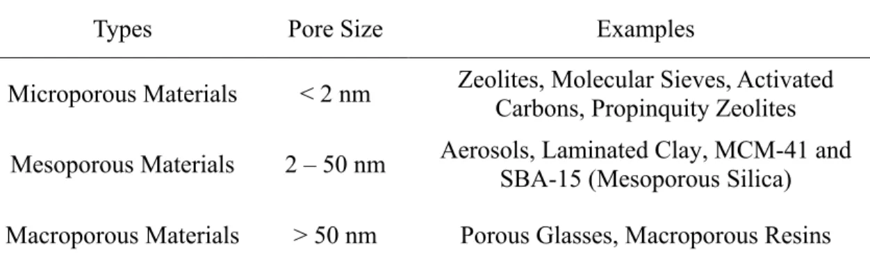
According to the definition of IUPAC (International Union of Pure and Applied Chemistry),2 porous materials can be divided into three types: microporous (with pore
diameter < 2 nm), mesoporous (pore size in the range of 2 – 50 nm) and macroporous materials (pore size > 50 nm) (Table 2.1). Among them, mesoporous materials, especially ordered mesoporous materials, are of the most widely studied for applications as sensors, catalysts, in chemical separations, electronic applications and so on in the past two decades.3-8
Table 2.1 Types of porous materials and some examples
Types Pore Size Examples
Microporous Materials < 2 nm Zeolites, Molecular Sieves, Activated Carbons, Propinquity Zeolites Mesoporous Materials 2 – 50 nm Aerosols, Laminated Clay, MCM-41 and SBA-15 (Mesoporous Silica) Macroporous Materials > 50 nm Porous Glasses, Macroporous Resins
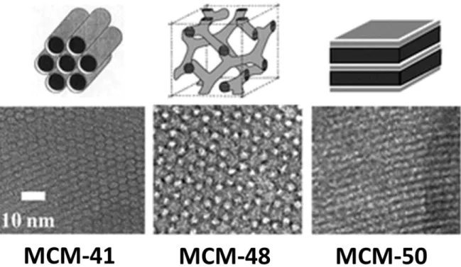
Figure 2.1 Mesoprous materials of M41s family: structural models of M41s (top) and TEM images (bottom) of the final materials. (Reproduced from9)
Ordered mesoporous materials are a family of nanoporous materials that have periodically aligned two- or three-dimensional porous structures, and uniform pore sizes ranging from 2 to 50 nm. These series of unique porous materials were firstly invented in the early 1990s (M41s series of porous silicas, Figure 2.1), separately by Japanese scientists and Mobil’s scientists using the surfactant self-assembly approach.10-12 The research
interest in the field of ordered mesoporous materials originates from conventional zeolites and molecular sieves possessing ordered micropores (< 2.0 nm) and crystalline frameworks. At that time, numerous scientists were pursuing novel catalytic systems with large-pore-size molecular sieves for heavy petroleum oil conversion involving macromolecules. Since then, with their unique properties such as high surface areas, periodically arranged monodispersed mesopore channels, tunable pore sizes, alternative pore structures, uniform nanosized or microsized frameworks, large particle sizes, and various compositions and morphologies, ordered mesoporous materials have shown great potentials in many fields.1,13-15 These diverse fields, include adsorption,14 separation and immobilizations,16 catalysis,3,13,15,17,18, drug delivery19,20 and energy conversion and storage.21-24
2.2 Synthesis of Mesoporous Materials
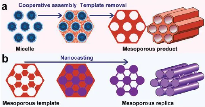
Figure 2.2 Scheme of two representative synthesis routes for ordered mesoporous materials: (a) soft-templating method and (b) hard-soft-templating (nanocasting) method. (Reproduced from 25)
The synthesis methodology for ordered mesoporous materials features the templating concept which was proposed over twenty years ago. Generally speaking, the templates for the generation of mesopores can be divided into two classes. The first ones are soft templates (Figure 2.2A), which usually refer to ‘‘soft’’ molecules (most of them are surfactants) like cetyltrimethylammonium bromide (CTAB), and amphiphilic block copolymers such as commercial Pluronic (poly(ethylene oxide)–poly(propylene oxide)– poly-(ethylene oxide), PEO–PPO–PEO) like P123 (PEO20PPO70PEO20).10,11,15,17,26 This
surfactant self-assembly approach for the fabrication of highly ordered mesoporous materials has led to a series of interesting research areas that have stimulated the growth of a large international community focused on mesostructured materials. The second ones are hard templates (Figure 2.2B), which are the preformed ordered mesoporous materials with rigid frameworks, such as ordered mesoporous silica, carbon, and colloidal crystals.25,27-32
some special ordered mesoporous materials (i.e. the replicas), such as metal sulfides, silicon carbides, etc.; however, the tedious multi-step procedure at the sacrifice of costly hard templates makes it unsuitable for mass production of mesoporous materials, and the obtained replicas have limited pore sizes due to the limited pore wall thicknesses (usually less than 10 nm). By contrast, the soft templating approach is more versatile, flexible and effective and is promising for large scale synthesis. More importantly, through this approach,the mesopore structure, shape, and pore size can be easily adjusted by controlling the synthesis conditions (temperature,ionic strength, pH) andthe properties ofthetemplate molecules (hydrophobic/hydrophilic volume ratio, hydrophobic length, etc.).15 As a
representative, the evaporation induced self-assembly (EISA) method was pioneered by Brinker and co-workers forthe synthesis of ordered mesoporous materials.33,34 This method,
combining sol–gel chemistry with molecular self-assembly, provides the flexibility to produce other types of mesostructures, such as monoliths and thin films with larger pore sizes comparedtothose derived fromthe solution-phase synthesis.
2.3 Chemical Composition of Mesoporous Materials
Figure 2.3 SEM and TEM images of mesoporous silicas SBA-15 (A), KIT-6 (B) and SBA-6. (Adapted from refs23,35,59)
Among all the mesoporous materials, silicate ones are most widely synthesized. This kind of mesoporous material is usually prepared via silicate sol–gel process using sof
t-templating method. It is well-known that the first ordered mesoporous material was reported by Yanagisawa et al. in 1990.12,36 Subsequent research by Mobil Oil Corporation
generated MCM-41 and the M41S family of mesoporous silicas.10,11 Then, silica based
mesoporous materials with different mesostructures have been synthesized.61 The TEOS as
silica building block is widely used due to the easy control of its hydrolysis, and long chain ammonium surfactants, amines or triblock copolymers as templating agents are normally adopted. Some of the well-known mesoporous silica materials (Figure 2.5) are in the M41s series including MCM-41, MCM-48, MCM-50 etc.,37 HMS and MSU series,38,39 the KIT
series including KIT-5, KIT-6 etc.,35 the SBA series including SBA-1, SBA-6,10,40 SBA-2,
SBA-12,41,42 SBA-15 26,41 and SBA-16, etc.,41 the FDU series including FDU-1, FDU-5,
FDU-12, FDU-13 etc.43-48 and the AMS series.49-51
Beside the mesoporous silica, inorganic non-silicate mesoporous materials, such as metal oxides, metal sulfides and pure metals, have also attracted much attention due to their extensive applications or potentials in various fields like electronic, magnetic and optical areas, catalysis, sensors and hydrogen storage. These mesoporous materials are also usually synthesized by surfactant directed self-assembly soft-templating method. After the EISA process was invented, as a universal method, much more non-silicate mesoporous materials were prepared since the hydrolysis of non-silicate precursor should be controlled well and EISA process will make this well regulated. Mesoporous metal oxides of zirconia and titania should be the representatives of non-silicate mesoporous materials. They were firstly synthesized by F. Schüth’s and Jackie Y. Ying’s group, respectively.52,53 Various other
mesoporous materials including TiO2, ZrO2, Al2O3, Nb2O5, Ta2O5, WO3, HfO2, SnO2, and
mixed oxides SiAlO3.5, SiTiO4, ZrTiO4, Al2TiO5 and ZrW2O8 have also been synthesized
using amphiphilic block copolymer templates and inorganic salt precursors.36,54-56 At the
same time, the formation mechanism and kinetics of mesoporous metal oxides by the EISA technique has been elucidated by several researchers.36,57 As the demand of new materials
for sensors and other novel nanostructured devices, mesoporous metal sulfides, platinum and tin have also been synthesized by a new direct self-assembly method.36 Recently,
cubic mesostructures have been synthesized by surfactant-driven self-organization of soluble clusters.36
Although the synthesis of many non-siliceous inorganic mesoporous materials could be achieved by direct assembly, their structural ordering are poor and mechanical strength and thermal stability are also low after removal of the surfactants.36 There are still many
non-silica mesoporous materials which cannot be synthesized. As another general synthesis technique, the nanocasting (hard-templating) strategy has become a more general pathway to synthesize a broad range of mesoporous materials. As mentioned above, highly ordered mesoporous silica materials such as MCM-48, SBA-15, KIT-6 are normally employed as ‘‘hard-templates’’. After the infiltration and consolidation, mesoporous replica materials are obtained after removal of the silica template by dissolution with aqueous NaOH or HF. Various mesoporous metal oxides and metal nanowires including Fe3O4, γ-Fe2O3, In2O3,
Co3O4, CuO, Cr2O3, NiO, Au, Ag, Pd, Ni, Cu, Ge, mixed metal oxides and Perovskites
have been synthesized by nanocasting.36,58,59 These kinds of mesoporous materials hold
great interest for photovoltaic and thermoelectric devices, fuel cells, hydrogen separation membranes, sensors and other device applications.
Mesoporous carbons are another kind of important non-silica mesoporous materials. Due to their large surface area, tunable pore size, good electrical conductive properties, and excellent thermal and chemical stabilities, mesoporous carbons show wide applications in adsorption,60 catalysis,61 fuel cells,62 and energy storage.23 Ordered mesoporous carbon
materials can be synthesized via the hard- and soft-templating approaches.63 By using
colloid spheres or ordered mesoporous silica as the hard templates, ordered mesoporous carbons with tailored pore size, structure and even graphitized carbon frameworks have been successfully synthesized.24,30,64 However, this hard-templating method suffers from
drawbacks, such as it is a time-consuming, costly procedure and hazardous in nature, and thus it is not suitable for large-scale synthesis. By contrast, the soft-templating method is usually accomplished via an organic-organic self-assembly process by choosing an
appropriate amphiphilic molecule and a carbon precursor, which has been extensively investigated.65
2.4 Mesoporous Materials with Different Morphologies
Morphologies of mesoporous materials should involve two important subjects: the micromorphology and macromorphology. Micromorphology is referred to the pore structure, which is decided by the pore size, spatial symmetry of mesopores and even pore volume. The other one, macromorphology, refers to the shape or the external morphology of mesoporous materials at macro-scale. These external shapes often present the forms of powder, nanorods, thin films, fibers, monoliths, microspheres and so on. The application fields and the practicability of mesoporous materials are highly depending on their morphology.
2.4.1 Tuning Morphologies of Mesopores at Micro-Scale
The pore size is a very important factor which affects the application aspects of the obtained mesoporous materials. For mesoporous materials prepared by the hard-templating method, their pore sizes highly depend on the properties of the hard template, especially the thickness of template pore wall, which is tedious to vary. For mesoporous materials prepared by the soft-templating method, their pore size is decided by the size of the hydrophobic part of the micelle formatted during the synthesis process and composed by the surfactant-precursor composites.42,66 Thus, the pore size of the obtained mesoporous materials could be varied by changing the soft-template (surfactant) with different hydrophobic chains. When using ionic surfactants, the pore size of the prepared mesoporous materials could be tuned with adoption of surfactants with different alkyl chain lengths.11 Mesoprous materials synthesized on the basis of nonionic surfactants such as
PEO-PPO-PEO triblock copolymers as templates, normally exhibit larger mesopores compared to the ones obtained with cationic surfactants due to the longer hydrophobic segments of such surfactant. Thus, high-molecular-weight copolymers with long