Design of a Mechanism to Increase Lateral Force Resistance of an Autonomous
Ship Hull Cleaning Robot
by Harith Morgan
Submitted to the
Department of Mechanical Engineering
in Partial Fulfillment of the Requirements for the Degree of Bachelor of Science in Mechanical Engineering
at the
Massachusetts Institute of Technology
May 2020
© 2020 Massachusetts Institute of Technology. All rights reserved.
Signature of Author:
Department of Mechanical Engineering May 8, 2020
Certified by:
Douglas Hart Professor of Mechanical Engineering Thesis Supervisor
Accepted by:
Maria Yang Professor of Mechanical Engineering
Design of a Mechanism to Increase Lateral Force Resistance of an Autonomous
Ship Hull Cleaning Robot
by Harith Morgan
Submitted to the Department of Mechanical Engineering on May 8, 2020 in Partial Fulfillment of the
Requirements for the Degree of
Bachelor of Science in Mechanical Engineering
ABSTRACT
Marine biofoul accrues on ship hulls and increases the resistance of a ship during voyage. This is a widespread issue within the shipping an industry—which supports the vast majority of global trade. To address this problem, we are developing Bio-Inspired HullCrawler—an
autonomous robot capable of cleaning ship hulls while a ship is underway. The novelty of our design centers on the bio-inspired suction cups that are cast as composite silicon elastomer. The purpose of this thesis is to look specifically at the lateral force resistance of elastomeric suction cup mechanisms. Here we propose new design concepts for the attachment system to improve on the drag force resistance of the HullCrawler device.
Thesis Supervisor: Douglas Hart
Acknowledgements
Thank you very much to Alban Cobi for your guidance throughout this project and for making the time and putting in the effort to mentor me all the while, showing how my development as an
engineer and as a researcher was a priority for you. I would also like to thank Hatsopolis Microfluidics Lab(HML) for being a welcome family of researchers and for setting a good example of how to balance life and the important pursuit of discovery. Thank you for Wendy
1
Contents
1. Introduction
1.1. Overview……….3
2. Background
2.1. Existing Biofouling Solutions……….5 2.2. Limits of Existing Biofouling Solutions……….7
3. HullCrawler Initial Prototype
3.1. Design and Function………...8
4. HullCrawler Challenges
4.1. Slippage………10 4.2. Maintaining Proper Orientation………14
5. Design of a New Lateral Force Resistance Mechanism
5.1. Revising Design Requirements……….15 5.2. Design Concepts………...19
6. Conclusion
6.1. Future Work………...22 6.2. References………...23
2
List of Figures
1-1: Example of what a fouled ship hull, person for scale
1-2: Visualization of the different areas of a ship that experience biofouling
2-1: Representative devices of state-of-the-art robot hull attachment technology (a)
Roving Bat (b) Hull Wiper (c) Fleet Cleaner (d) Robotic crawler from Invert
Robotics
3-1: HullCrawler Prototype
3-2: Suction cup design from HullCrawler version 1
4-1: Path of the hull crawler along the ship's hull surface
4-2: Drag force equation
4-3: Free body diagram of HullCrawler on hull surface
4-3: function dependencies of friction force
4-4: Miyake et al. experimental results correlating friction force of suction cup and
pressure differential in suction cavity
4-5: Rear view of hull crawling robot disorienting because drag, compromised
sealing for suction cups that require perpendicular orientation to surface
4-6: Graphic showing current suction cup orientation needed for proper sealing and
attachment
5-1: Experiment measuring lateral force resistance for with varying amounts of
suction stem tilt (a) perpendicular orientation (b) angled stem at approximately 55ᵒ
5-2: Graphic showing increasing in suction cavity volume with titling stem
5-3: Graphic showing where design concepts are located on the Bio-Inspired
HullCrawler architecture
5-4: Sketch of Concept 1
5-5: Sketch of Concept 2
3
Introduction
1.1 Overview
Marine biofouling describes the phenomenon in which marine life sticks to surfaces submerged in the fauna rich environment of lakes, seas, streams, and other bodies of water. As ships travel through different water environments they encounter a variety of marine species. As shown in figure 1-2, Organisms such as barnacles and mussels attach to the different parts of a ship and create homes for themselves aboard the vessel surface. Enough species can attach to a ship’s hull for a new ecosystem to develop on its surface [1]. An example of this can be seen in figure 1-1. Drag minimization is an important consideration in the design of ship hulls.
Biofouling detracts from the hydrodynamic efficiency of a vessel by introducing organisms that increase the surface roughness of the ship and increase drag. Even incremental increases in drag force are significant due to the large distances that ships travel—often crossing entire oceans during standard operation [2]. The energy to overcome this additional drag force comes from burning more fuel. Consequently, as ships foul it is necessary for them to burn more fuel to travel the same distances. The shipping industry accounts for 90% of the world's trade, forming a $380 billion market within the global economy, because shipping offers a greater fuel efficiency per kg of cargo than comparable modes of long distance transport, e.g. airplane delivery [3][4]. Fouling can increase the fuel consumption of a ship by as much as 40% in only six months of exposure [5]. With fuel costs already claiming 50-60% of total shipping cost, the additional cost of fuel to overcome the effects of biofouling quickly becomes an overwhelming burden for the shipping industry [6].
4
Figure 1-1: Example of a fouled ship hull, person for scale [7]
5
Background
2.1 Existing Biofouling Solutions
The issue of cleaning biofouling has been a reality since the inception of the shipping industry. As such there is a long history of proposed solutions. Recent advances in technology have allowed for more autonomous robotic solutions, however, much of the industry still uses semi-manual processes many of which require dry-docking [8]. Dry-docking is a process by which ships are brought into harbor and docked in special basins that can be drained and flooded at will to allow access to the underside of a ship. Dry-docking is an expensive process costing up to $100K/day for LNG tanker sized vessels [9]. Even simply docking of a boat for hull cleaning can be expensive because disallowing a ship to sail holds opportunity costs. Any solution that does not necessitate dry-docking avoids this cost and is thus a preferred approach. The state-of-the-art in vessel hull cleaning is composed of a variety of manual and semi-autonomous
submersible cleaning robots. For the purpose of comparing against the best current solutions this paper will focus on only semi-autonomous robotic solutions.
The Roving Bat by ECA HYTEC, shown in figure 2-1(a), is an aquatic robot designed to inspect and clean ship hulls. The device is capable of swimming and reorienting itself while under water. During cleaning it adheres to the ship surface by using thrusters to counteract gravity or any other detaching force. The Hull Wiper, shown in figure 2-1(b), similarly inspects and cleans ship hulls. This device offers greater inspection capabilities than the Roving Bat and uses negative pressure to remain attached to the ship hull. The Fleet Cleaner hull cleaning robot, shown in figure 2-1(c), uses permanent magnets to adhere to the ship hull. These devices are not the only hull cleaning products available, however, they represent the variety of state of the art hull cleaning robots and the currently employed methods of attachment [8]. The Robotic Crawler
6
by Invert Robotics, shown in figure 2-1(d), is a device that, although it is designed solely for farm tank and airplane fuselage inspection, offers a different means of hull attachment than the aforementioned technologies. The Robotic Crawler employs sliding suction cups to attach to surfaces during inspection.
(a)
(b)
7
(d)
Figure 2-1: Representative devices of state-of-the-art robot hull attachment technology (a) Roving Bat [10] (b) Hull Wiper [11] (c) Fleet Cleaner [12] (d) Robotic crawler from Invert Robotics [13]
2.2 Limits of Existing Biofouling Solutions
Any hull cleaning robot product today falls into one of the categories of attachment technology represented by the stated devices: The Roving Bat, Hull Wiper, Fleet Cleaner, and Robotic Crawler. These categories–thruster technology, negative pressure generation, permanent magnets, and sliding suction cups–each have their own setbacks.
Thruster technology and negative pressure generation suffer the same issue of being both energy expensive. The energy cost of thrusters is such that the Hull Wiper device requires 37kW of power for operation, and this figure does not account for energy consumed in powering the companion surface equipment for the robot. Negative pressure generation is similarly costly. The Roving Bat requires 90kW during operation. This energy cost makes such devices financially expensive and positions this technology as a functional but sporadic solution to the problem of marine biofouling. As companies and individuals are discouraged from frequent use, ships are allowed to go longer periods of being fouled. This reality coupled with the fact that such energy expensive methods are simply inefficient makes these solutions suboptimal.
8
Permanent magnet attachment, conversely, is very energy efficient, however, such attachment demands ferromagnetic properties of the ship hull material. Additionally, research has shown that permanent magnet attachment systems cause robots to detach when going over bumps and weld lines on the ship surface [14]. These limitations on hull material means that permanent magnet attachment is not a robust mechanism for this application. Sliding suction cup technology similarly offers an energy efficient solution, but it is also limited in that it only functions on surfaces on which the suction cup can easily slide across. Given that the problem we seek to address is fouling of ship hulls, it is a functional requirement for any proposed solution to be able to move freely on a fouled, and therefore not smooth, surface.
A solution that improves on the current state of the art must be one that is energy efficient and robust while affording the same or greater attachment to, and flexibility of movement on, a ship’s hull surface.
Bio-Inspired HullCrawler Initial Prototype
3.1 Design and Function
To meet these challenges of hull attachment during cleaning, my lab has developed Bio-Inspired HullCrawler, shown in figure 3-1. This robot is designed to clean ship hulls while the ship is underway. It uses passive suction technology for attachment and treads, akin to that of a tank, for movement. As the robot moves across the hull surface individual bio-inspired suction cups attach and detach from the surface with the rotation of the treads through a continuous peeling mechanism. The combination of these two mechanisms allows for an energy efficient and robust system. The adaptability of this system comes from the design of the bio-inspired
9
suction cups themselves and from the coupling of their attachment and detachment to the movement of the treads.
Figure 3-1: Bio-Inspired HullCrawler Prototype [8]
The suction cups, shown in figure 3-2, are a composite silicone elastomer. The cups are cast such that the layer that comes in contact with the hull surface–the contact layer–is of a less stiff elastomer than the layer that interfaces with the stem of the suction cup–the stiff layer, similar to suction parts of animals such as the octopus and northern clingfish [15,16]. The elastic deformation of the stiff layer allows the suction cup to passively maintain a pressure differential across the suction cup. The ability of our suction cup design to adapt to rough surfaces comes from the compliance of the contact layer wherein the contact face of the suction cup conforms to asperities the size of which resembles a fouled ship hull surface [8].
10
Figure 3-2: Suction cup design from Bio-Inspired HullCrawler version 1 [8]
Bio-Inspired HullCrawler Challenges
4.1 Slippage
One of the biggest challenges in designing a robot that can clean a ship hull while
underway is overcoming drag force. Suction force opposes detachment forces, e.g. gravity, ocean currents or turbulence, that might pull the robot away from the hull surface. In addition to
remaining attached to the hull surface, it is necessary for the robot to also be laterally constrained, inhibiting unwanted movement tangential to the hull surface. Lateral constraint protects the robot against slipping off the rear end of a ship and it ensures we have control of the movement of the robot along the hull. The design intent is to traverse the vessel hull surface in a zig-zag path, as shown in figure 4-1, to minimize the directions from which the robot can
11
Figure 4-1: Path of the hull crawler along the ship's hull surface [8]
As the overall design of the robot is still in the iteration phase, we use estimated figures
to calculate the approximate expected drag force. We take the density of water, ρ, to be 1000 𝑘𝑔
𝑚3.
For our design application we know ships (LNG Tankers or Cargo Ships) typically travel at a maximum speed, v, of about 30 knots, which equates to 15.43 𝑚
𝑠 [17]. For the full scale product,
we project the frontal surface area of the robot, Aref , will be about 0.25 𝑚2, similar to that of
other vessel hull cleaning robots such as Hull Wiper, Fleet Cleaner, and Roving Bat [10-13]. The drag coefficient of the device is highly dependent on its final geometry and hydrodynamic
profile. Well streamlined bodies yield a drag coefficient of ~0.1 [18]. For first-order calculations we take the worst case scenario drag coefficient of our robot to be ~0.5, close to the coefficient of drag of a half sphere, and calculate an approximate drag force of 14kN, where the drag force is given by the equation in fig 4-2.
12
𝐹
𝑑𝑟𝑎𝑔
= 𝐶
𝑑
1
2
𝜌𝑣
2
𝐴
𝑟𝑒𝑓
Figure 4-2: Drag force equation
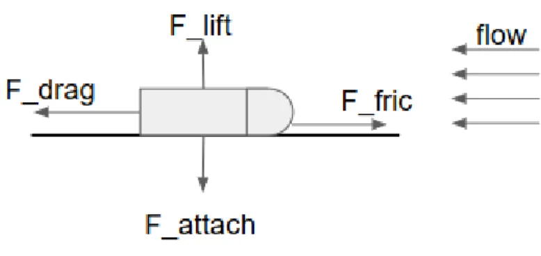
Figure 4-3: Free body diagram of HullCrawler on hull surface [8]
For the device to remain in static equilibrium whenever the drive system is dormant. The friction force, F_fric, must be equal to the drag force, F_drag. Research has shown that friction force between an elastomer and substrate depends on substrate roughness (𝜇), pressure
differential between suctioned area and surrounding area (∇𝑃), and viscosity of the fluid between the elastomer and the substrate(𝜂) [19].
𝐹
𝑓𝑟𝑖𝑐𝑡𝑖𝑜𝑛
= 𝑓(𝜇, ∇𝑃, 𝜂)
13
In their experiments Miyake et al used a 155mm diameter suction cup and measured the friction force of this suction cup on both concrete and glass substrates. They varied the viscosity of the fluid between the suction cup and substrate, and used actuators to vary the lateral pull speed of the suction cup along the surface.
While varying the pressure difference between the suction cavity and the surrounding fluid, Miyake found a positive correlation between greater pressure differential and greater friction force. The results in figure 4-4 show a 3x increase in static friction from a suction cavity pressure of -1kPa to a pressure of -9kPa. The impact of pressure differential on kinetic friction is less significant. However, static friction is the more important force in our application because once static friction is overcome, the robot is in danger of detachment from the hull surface.
Figure 4-4: Miyake et al. experimental results correlating friction force of suction cup and pressure differential in suction cavity [19]
Laterally constraining our device requires a design that considers these parameters as they exist in our underwater, underway application environment.
14
4.2 Maintaining Proper Orientation
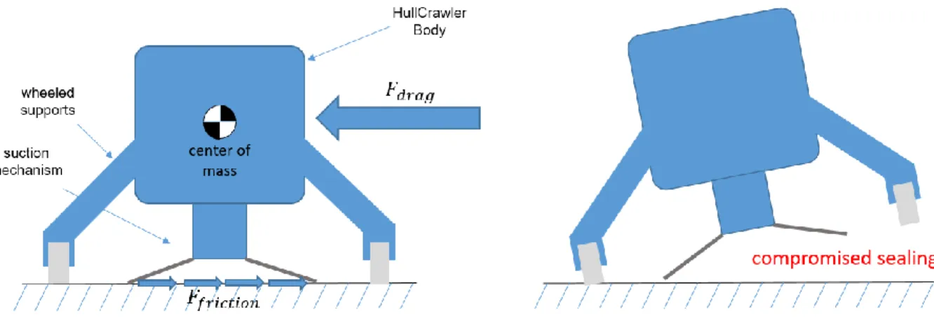
Another challenge that we face in improving the design of HullCrawler, is addressing the issue of our device disorienting under the influence of drag. Our device is meant to adhere to the hull of a ship which is effectively a flat surface, relative to the size of our device, whereupon our device can only exist on one side. Consequently, the center of mass of the device cannot be coplanar with this surface. If we model the drag force on the robot body as a net force acting only on the center of mass as shown in figure 4-5, we see that overall mechanics of a hull cleaning robot experiencing drag forces resemble a cantilevered beam where suction attachment to the hull and friction at this interface act as the fixed support and the drag force is the load. This is an issue because our current design relies on the robot maintaining a perpendicular orientation to the ship hull surface, as shown in figure 4-6. Disorientation would impede subsequent suction cups, revolving with the treads, from sealing properly and attaching.
Figure 4-5: Rear view of hull crawling robot disorienting because drag, compromised sealing for suction cups that require perpendicular orientation to surface
15
Figure 4-6: Graphic showing current suction cup orientation needed for proper sealing and attachment
Design of a New Lateral Force Resistance Mechanism
5.1 Revising Design Requirements
To mitigate slippage and resolve the issue of disorientation I propose a revision of the design requirements for our device such that the suction stems are made to tilt during the standard operation of the device. Given the problem of disorientation is a consequence of satisfying other functional requirements of the design, preventing stem titling would require major revisions to the overall robot geometry to increase what would be the beam stiffness in the analogy described previously. Such revisions are out of the scope of this paper. Imposing a
16
design requirement of making stem tilting a part of standard operation also, as we will see, addresses the issue of slippage.
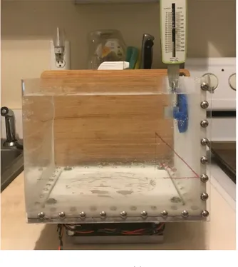
Our suspicion that suction cup stem orientation might affect lateral force resistance in suction cups was born from an incidental observation that suction cups were less easily slid across a smooth surface when the force to move them was applied in such a way that it tilted the stem. We performed an experiment with our bio-inspired suction cup design to validate a
connection between suction stem orientation and suction cup lateral force resistance. We created a testing setup to mimic the underwater environment of our design application. The bio-inspired suction cup has a diameter of 50mm and is a silicone elastomer with ecoflex 00-10 (Smooth-On, USA) soft layer and mold star 30 (Smooth-On, USA) stiff layer. With the suction cup attached to a submerged surface we used a Chatillon spring scale to measure the resistance of the suction cup to lateral force. We observed a peak force resistance of 15 ± 1 Newtons when the suction stem was tilted at approximately 55 degrees, as compared to a peak resistance of 9 ± 1 Newtons in the case where the stem was oriented perpendicular to the substrate surface. These results show a 60% increase in lateral force resistance. We hypothesize this is due to an increase in pressure differential between the suctioned area and the surrounding area.
17
(a)
(b)
Figure 5-1: Experiment measuring lateral force resistance for with varying amounts of suction stem tilt (a) perpendicular orientation (b) angled stem at approximately 55ᵒ
18
Figure 5-2 illustrates how bending the stem, causes the volume inside the cavity increases. The seal along the rim of the suction cup impedes flow into this cavity meaning the volume increase of the cavity happens before fluid is allowed to fill the void [8]. This causes a decrease in the pressure in the cavity. The greater pressure differential caused by this decrease in internal pressure pulls down on the elastomer with greater force, and deforms the elastomer to create a more intimate contact with the substrate, thereby improving friction. This understanding is confirmed in experiments done by Miyake et al where they measured an increase in friction force correlated with increases in induced pressure differential.
19
5.2 Design Concepts
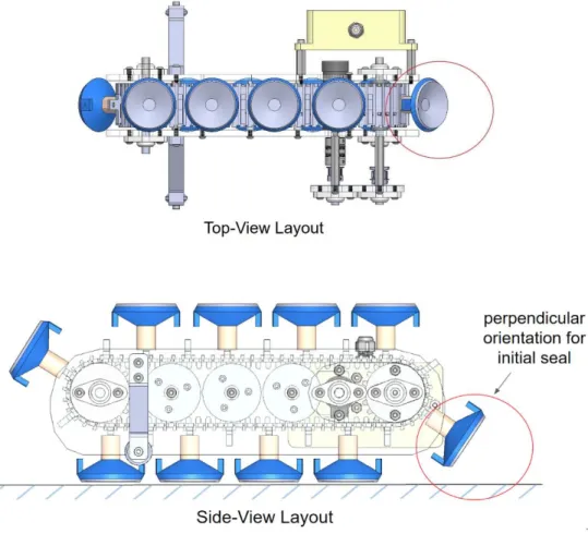
Figure 5-3: Graphic showing where design concepts are located on the Bio-Inspired HullCrawler architecture
We have two design concepts that incorporate stem tilting into the function of the Bio-Inspired HullCrawler. These concepts are meant to replace the current attachment mechanism subassembly shown in figure 5-3. The predominant difference between these concepts is the actuation, where concept 1 (shown in figure 5-3) is engaged by downward force and concept 2 (shown in figure 5-4) is engaged by magnetic repulsion.
20
Concept 1 is a symmetric linkage based mechanism. Similar to our current attachment mechanism assembly, this design interfaces with the treads of the Hull crawler through a rigid block. This block then connects to linkages that orient the suction stem. The length of these linkages is designed such that the stem moves from an orientation perpendicular to the substrate surface to an angled orientation, as the rigid block is moved down relative to the suction cups and closer to the substrate surface. The symmetry of the design with two suction cups resolves issues of instability that might be caused by unbalanced forces internal to the mechanism assembly. Specifically, as the suction cup moves into an angled orientation, there is a lateral reaction force onto the rigid block from the linkages. By mirroring the linkage subassembly, any lateral internal reaction forces are nullified. The linkages are also designed to minimize lateral movement of the contact face of the suction cups, because this face will be in contact with the hull surface as the suction stem sweeps through its trajectory. The actuation of this concept mechanism is a downward motion of the rigid block. This comes from the movement of the tread as it moves this interfacing block around the curved front end of the tread path.
21
Concept 2 is a magnetically actuated linkage mechanism. The linkage here is designed similarly to the linkage mechanism in concept 1; meeting the same requirement of moving the suction stem from a perpendicular to an angled orientation as it sweeps through its path. This design addresses the issue of imbalanced reaction forces by centering the linkage subassembly within the larger attachment mechanism architecture. Given that the lateral movement of the contact face of the suction cup is similarly minimized throughout the stroke of this linkage mechanism, centering the linkage mechanism allows the center of mass of the robot to always be above the attachment point of contact, relative to the hull surface. The force of actuation for this mechanism comes from repulsion between the permanent magnets embedded in the top of the suction stem and the magnetic strip that runs along the bottom side of the robot.
Based on our findings on the general effect of suction stem tilting on frictional force of suction cups, both of these concepts are viable solutions for increasing the overall lateral force resistance of the HullCrawler.
22
Conclusion
6.1 Future Work
The foremost next steps in this project are fabrication and further experimentation. In the same way that our first prototype of the Bio-Inspired HullCrawler yielded lessons and findings that allowed us to better design for our target application, many of the intricacies of how our system will behave are best understood through tests that mirror the real conditions of our intended working environment. For this, the plan is to fabricate the proposed attachment mechanisms and test the lateral force resistance and strength of adhesion of the robot in a flow tank.
Beyond this, there is also room to revisit the experiment relating suction stem tilt and suction cup lateral force resistance. As they are, the experiments completed provided sufficient support for the concept of incorporating stem tilt in standard operation, however, there is room to rerun these experiments with more precise measurement equipment. This will allow us to better understand the behavior of this phenomenon and perhaps establish theory for how it works.
23
References
[1] Gregory D. Bixler and Bharat Bhushan. “Review article: Biofouling: Lessons from Nature”. In: Philosophical Transactions of the Royal Society A: Mathematical, Physical and Engineering Sciences370.1967 (2012), pp. 2381–2417.issn: 1364503X.doi:10.1098/rsta.2011.0502 [2] Teodorović, Dušan and Janić, Milan.” Transportation, Environment, and Society.”
Transportation Engineering: Theory, Practice and Modeling. Butterworth-Heinemann, Oxford (2017): pp. 719-858
[3] International Chamber of Shipping. “Key Facts.” Accessed May 7, 2020. https://www.ics-shipping.org/shipping-facts/key-facts
[4] International Chamber of Shipping. “World Seaborne Trade.” Accessed May 7, 2020. https://www.ics-shipping.org/shipping-facts/shipping-and-world-trade/world-seaborne-trade [5] Woods Hole Oceanographic Institute. “The Effects of Fouling.” Marine Fouling and Its
Prevention. George Banta Publishing Co., Wisconsin (1952): pp. 3-19
[6] Elizabeth Stratiotis. “Fuel Costs in Ocean Shipping.” More Than Shipping. January 22, 2018. https://www.morethanshipping.com/fuel-costs-ocean-shipping/
[7] Gcaptain. Accessed May 7, 2020. https://gcaptain.com/hull-fouling-control-innovation/ [8] Cobi, A 2020, 'A Suction-Based Reversible Attachment and Locomotion Mechanism for an
Underway Vessel Hull Cleaning and Inspection Robot', unpublished master's thesis, Massachusetts Institute of Technology
[9] M. P. Schultz , J. A. Bendick , E. R. Holm & W. M. Hertel (2011) Economic impact of biofouling on a naval surface ship, Biofouling, 27:1, 87-98, DOI: 10.1080/08927014.2010.542809
[10] ECA Group. “Roving Bat.” Accessed May 7, 2020.
https://www.ecagroup.com/en/solutions/rovingbat-hybrid-rov
[11] HullWiper. “Technical Specifications.” Accessed May 7, 2020. https://www.hullwiper.co/why-hullwiper/
[12] Fleet Cleaner. “Technology.” Accessed May 7, 2020. https://www.fleetcleaner.com/technology/ [13] Invert Robotics. “Technical specifications of our robotic crawler”. Accessed May 7, 2020.
https://www.invertrobotics.com/robotic-crawler
[14] Bill Ross, John Bares, and Chris Fromme. “A Semi-Autonomous Robot for Strip-ping Paint from Large Vessels”. In:The International Journal of Robotics Re-search22.7-8 (2003), pp. 617– 626.issn:
0278-3649.doi:10.1177/02783649030227010.url:http://journals.sagepub.com/doi/10.1177/0278364903 0227010
[15] Ditsche, Summers, “Learning from Northern CLingfish: Bioinspired Suction cups attach to rough surfaces, 2019”
[16] Tramacere, “Structure and Mechanical Properties of Octopus vulgaris Suckers”, 2014 [17] https://www.cruisecritic.com/articles.cfm?ID=2978
[18] McCormick, Barnes W. (1979): Aerodynamics, Aeronautics, and Flight Mechanics. p. 24, John Wiley & Sons, Inc., New York, ISBN0-471-03032-5
[19] Miyake, Tohru and Ishihara, Hidenori and Yoshimura ,Motoi. 2007. “Basic Studies on Wet Adhesion for Wall Climbing Robots.” Proceedings of the 2007 IEEE/RSJ International Conference on Intelligent Robots and Systems San Diego, CA, USA, Oct 29 - Nov 2, 2007. http://bdml.stanford.edu/twiki/pub/Main/WetAdhesiveLitReview/MiyakeIshiharaYoshimura2007 .pdf
![Figure 1-2: Visualization of the different areas of a ship that experience biofouling [1]](https://thumb-eu.123doks.com/thumbv2/123doknet/14684990.560009/8.918.245.677.569.952/figure-visualization-different-areas-ship-experience-biofouling.webp)
![Figure 2-1: Representative devices of state-of-the-art robot hull attachment technology (a) Roving Bat [10]](https://thumb-eu.123doks.com/thumbv2/123doknet/14684990.560009/11.918.363.556.142.338/figure-representative-devices-state-robot-attachment-technology-roving.webp)
![Figure 3-1: Bio-Inspired HullCrawler Prototype [8]](https://thumb-eu.123doks.com/thumbv2/123doknet/14684990.560009/13.918.241.647.234.509/figure-bio-inspired-hullcrawler-prototype.webp)
![Figure 3-2: Suction cup design from Bio-Inspired HullCrawler version 1 [8]](https://thumb-eu.123doks.com/thumbv2/123doknet/14684990.560009/14.918.274.630.121.405/figure-suction-cup-design-bio-inspired-hullcrawler-version.webp)
![Figure 4-1: Path of the hull crawler along the ship's hull surface [8]](https://thumb-eu.123doks.com/thumbv2/123doknet/14684990.560009/15.918.189.749.126.469/figure-path-hull-crawler-ship-s-hull-surface.webp)
![Figure 4-4: Miyake et al. experimental results correlating friction force of suction cup and pressure differential in suction cavity [19]](https://thumb-eu.123doks.com/thumbv2/123doknet/14684990.560009/17.918.203.697.537.814/figure-miyake-experimental-results-correlating-friction-pressure-differential.webp)