Publisher’s version / Version de l'éditeur:
Vous avez des questions? Nous pouvons vous aider. Pour communiquer directement avec un auteur, consultez la
première page de la revue dans laquelle son article a été publié afin de trouver ses coordonnées. Si vous n’arrivez pas à les repérer, communiquez avec nous à PublicationsArchive-ArchivesPublications@nrc-cnrc.gc.ca.
Questions? Contact the NRC Publications Archive team at
PublicationsArchive-ArchivesPublications@nrc-cnrc.gc.ca. If you wish to email the authors directly, please see the first page of the publication for their contact information.
https://publications-cnrc.canada.ca/fra/droits
L’accès à ce site Web et l’utilisation de son contenu sont assujettis aux conditions présentées dans le site LISEZ CES CONDITIONS ATTENTIVEMENT AVANT D’UTILISER CE SITE WEB.
Internal Report (National Research Council of Canada. Division of Building
Research), 1973-01-01
READ THESE TERMS AND CONDITIONS CAREFULLY BEFORE USING THIS WEBSITE. https://nrc-publications.canada.ca/eng/copyright
NRC Publications Archive Record / Notice des Archives des publications du CNRC :
https://nrc-publications.canada.ca/eng/view/object/?id=632ecfc3-b21f-4b8e-9ec9-03d9e9a41a82 https://publications-cnrc.canada.ca/fra/voir/objet/?id=632ecfc3-b21f-4b8e-9ec9-03d9e9a41a82
NRC Publications Archive
Archives des publications du CNRC
For the publisher’s version, please access the DOI link below./ Pour consulter la version de l’éditeur, utilisez le lien DOI ci-dessous.
https://doi.org/10.4224/20358572
Access and use of this website and the material on it are subject to the Terms and Conditions set forth at
Performance of the mmoke control system, Library Building, University
of Ottawa
NA TIONAL RESEARCH COUNCIL OF CANADA DIVISION OF BUILDING RESEARCH
PERFORMANCE OF THE
SMOKE CONTROL SYSTEM, LIBRARY BUILDING, UNIVERSIT Y OF OT TAWA
by
C. Y. Shaw and G. T. Tamura
Internal Report No. 403 of the
Division of Building Research
Ottawa April 1973
PERFORMANCE OF THE
SMOKE CONTROL SYSTEM, LIBRARY BUILDING, UNIVERSITY OF OTTAWA
by
C. Y. Shaw and G. T. Tam.ura
PREFACE
The Division has been studying the factors affecting the migra-tion of smoke through multi-storey buildings for the past several years, and has developed a number of approache s to the control of smoke in the event of fire. Buildings incorporating these concepts are now being constructed and it is of great value to be able to determine how they perform. This report presents the results of one such series of tests that were made on the Library at the University of Ottawa. The Division is very appreciative of the Urn ve r s ityt s co-operation in per-mitting these tests to be made and also of the assistance that was
obtained from the consulting engineers, Pageau Morel Lefebvre
(Ottawa) Ltd , , who designed the smoke control system for the Library. The results of these tests, and other similar ones, will provide design and application data that can only be obtained by such direct experience. This kind of information is needed as a basis for rational building code regulations and for the de sign of systems that will meet the code requirements.
This report is a private record of what was done and of the results that were obtained: the information will ultimately be published in a form that better suits the needs of designers and code officials.
Ottawa N.B. Hutcheon
2-Central Control Station
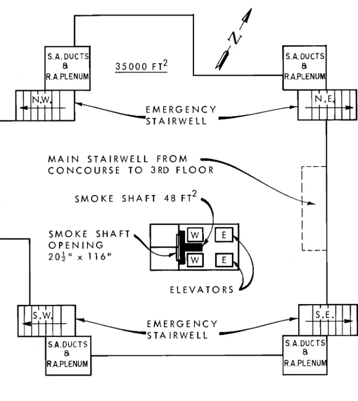
The central control station is located at the first floor. Sm.oke Shaft
Shaft Construction: One T shaped shaft of concrete construction with a total internal cross sectional area of 48 ft2 •
Sm.oke dampers:
Concourse to 6th Floor: Two m.ultiple blade dampers located side by side in the sm.oke shaft opening. The total open area is 16. 6 ft2 •
Basem.ent: Branch air ducts of the return air system. serve as intake ducts to the sm.oke shaft.
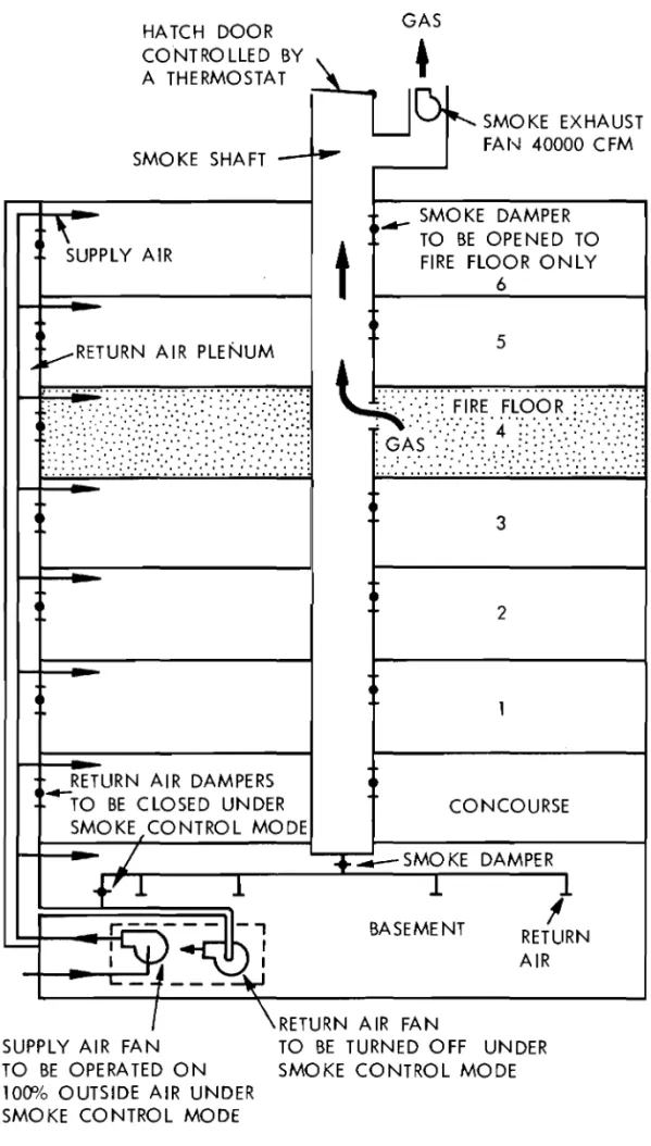
Exhaust fan: an exhaust fan with a capacity of 40,000 cfrn is installed at the top of the sm.oke shaft. Back draft dampers are provided at both side s of the fan. A m.otorized hatch door
controlled by a therm.ostat is also located at the top of the shaft.
Contr ol s: The dampers and hatch door are operated by electric controllers.
Operation (see Figure 2)
Autom.atic actuation with eithe r sm.oke detector or pull alarm. is found at each floor.
Sm.oke dampers on each floor can be opened with switches provided on the panel of the central control station.
Main supply air system. switches to 100% outside air. (The system. is de signed for operation at outside air tem.perature of 40 D F . )
The return air fan is shut down with return air dampers closed. The sm.oke damper on the fire floor is opened and the sm.oke exhaust fan is activated.
Alarm. is sent to the central heating plant.
When the tem.perature inside the sm.oke shaft rise s to about l20 D F ,
the hatch door is opened. Other Provisions
Com.m.unication system.: intercom. and loud speaker. Elevator: key ope rated switch for independent se r vi ce , Alarm. system.
3-TESTS
First Test: Pressure Me a su r em ent s
Tests were conducted with the 4th floor selected as the fire floor. Test AI:
A/c
s y stern in operation.With the
A/c
s y stern operating no rITl all y , pressure differentials across em e r g en c y stair and elevator doors at concourse, 4th and 6th floors were rn e a su r ed , Also pre s sure differentials f r orn 1 st floor to rn a in stairwell and f r om rn a in stairwell to outside were rn e a su r ed ,Test A2:
A/c
systern shutdown.With both the
A/c
s y st ern s and the sm oke control sy st.ern not operating, pressure differentials across erne r ge ncy stair and elevator doors at concourse, 4th and 6th floors were rn e a su r ed , Also pressure differentials f r om 1st floor to rn ai.n stairwell,and f r orn rn a in stairwell to outside were rn e a su red ,
Test A3: Air conditioning sy st ern operating in srn oke control m ode with no venting. With the srn oke exhaust fan shut down rn anu al l y , and the d ampe r opening at the fire floor sealed, pressure differentials Erorn 1 st floor to rn a in stairwell and rn a in stairwell to outside were rrie a su r ed , This te st was
conducted to det.e rrrrine the am ount of pre s surization provided by the supply air sy stern ,
Test A4: Sm oke control sy st ern in operation without rn e c hani c a.l venting.
With the srn oke control sy st ern ope rating, the sm oke exhaust fan shut down rn arrua.l l y and the seal r ern ove d f r orn the darn pe r opening at the fire floor, the following rn e a su r ern ent s were taken:
Test A4a: all stair and exit doors closed
i , Air flow into the smoke shaft through the d arnpe r opening.
i i , Pressure differentials across floor constructions between the 4th floor and floors above and below. iii. Pressure differentials across elevator and
ern e r g e n cy stair doors at the 4th floor.
i v , Pressure differentials Erorn 1 st floor to rn a in stairwell and f r om rn a in stairwell to outside. Test A4b: exit door in one ern e r g ericy stairwell open i , Pressure differentials across the stair door
of the SW errre rgency stairwell at the 4th floor with the exit door of this stair shaft open to out-side. All other stair doors closed.
4-ii , Pressure differentials across the stair door of the SE emergency stairwell at the 4th floor with the exit door of this stair shaft open to outside. All other stair doors closed.
Test AS: Smoke control system with mechanical venting. With the smoke control system ope rating and with the srn oke exhaust fan activated, the following measurements were taken:
Test ASa: all stair and exit doors closed
i , Air flow into the smoke shaft through the damper opening.
i i , Pressure differentials across floor constructions between the 4th floor and fl o o r s above and below. iii. Pressure differentials across elevator and
emergency stair doors at the 4th floor.
i v, Pressure differentials across the stair doors of the NE emergency stairwell at the concourse, 4th and 6th floors.
v , Pressure differentials from. l st floor to rn a in
stairwell and f r orn main stairwell to outside. Test ASb: exit door in one emergency stairwell open
Pressure differentials across elevator and stair doors at the 4th floor with the exit door of the NE stairwell open"
Test ASc: exit door and 4th floor stair door in one emergency stairwell open
i , Pressure differentials across elevator and stair doors at the 4th floor with both the exit door and the 4th floor stair door of the NE stairwell open.
i i , Air flow through the open stair door at the 4th floor.
All measurements are listed in Table
1.
Because of the fluctuations in pressure difference readings caused by wind and movement of elevator cars, readings given in the Table are app r o xirn at e mean values.DISCUSSION OF PRESSURE MEASUREMENTS
With the air conditioning system off (Te st A2), pre s sure measure-ments indicate that the neutral plane of the elevator shafts is found at
-5-neutral plane and flow out of the shaft above it. Air flow is out of the stair shafts at both lower and upper levels with flow into the shaft at m.id levels. This was probably caused by the inflow of outside air through the leakage opening s of the bottom. exit door. The com.parison of the pre s sure difference between the 1 st floor and outside with the air conditioning system. on (Test AI) and off (Test A2) indicates a pressurization of about O. 02 in. of water. With pressurization, the direction of flow as shown in Table I is into the stair shafts from. all floor spaces. The flow pattern across the walls of the elevator shafts, however, indicate s the characteristic flow pattern caused by stack action as indicated previously. With the air conditioning system.
operating in the sm.oke control m.ode but with the sm.oke shaft inoperative (Te st A3), the supply air system. provided building pre s surization of 0.31 in. of water.
The objective of the sm.oke control system. of this building is to lower the pressure in the fire floor to such an extent that air enters from. the surrounding areas into the fire floor. This is achieved by
venting gas in the fire floor to outside through a sm.oke shaft. Te sts A4-a and A5-a were therefore conducted to check the flow pattern across the fire floor enclosure with the sm.oke control system. in operation. Test A4-a was conducted with the sm.oke exhaust fan shut down so that air was exhausted to outside through the sm.oke shaft due to building
pressurization and stack effect. Test A5-a was conducted with the sm.oke exhaust fan in operation. Both tests clearly show that air flow directions originate from. the adjacent areas into the fire floor and from. the fire floor to outside via the sm.oke shaft. These tests indicate that the operation of the smoke control system under the conditions specified (low tem.perature fire) will thus prevent sm.oke spread from. the fire floor to its surrounding s ,
Air flow rate s into the sm.oke shaft at the fire floor were taken during Tests A4-a and A5-a with rates of 9,400 cfm. and 15,500 cfrn
re spe cti ve ly , The comparison of pre ssure reading s taken during the two tests shows that the reduction in pressure in the fire floor relative to adjacent space s increased with the venting capacity of the sm.oke shaft as expected. The rate of air flow into the sm.oke shaft in Test A4-a was taken with the hatch door at the top of the shaft closed and with the exhaust fan shut down. By opening the hatch door, the air flow rate increased to 17,800 cfrn , an increase over Te st A5 -a where the exhaust fans were on and the hatch door closed.
The rate of air flow into the shaft at the fire floor obtained in Test A5-a was 15,500 cfm. which is m.uch less than the rated fan capacity of 40, 000 cfrn , This was probably caused by the following factors:
(1) Visual observations which indicated that there were large gaps be-tween damper and damper frame as well as bebe-tween individual damper blades. The leakage area is esti:m.ated to be roughly 15 per cent
-6-of the damper opening. On this basis the total leakage area is approximately 105 per cent of the vent opening at the fire floor indicating that the total leakage flow might have been as high as 15,000 efm.
(2) Leakage through the shaft walls.
(3) Frictional pressure drop inside the shaft due to the Tshaped cross section.
Test A5b differs from Test A5a in that the exit door of the NE emergency stairwell was opened to outside. Pressure difference readings across the 4th floor stair door of the stairwell indicates that the opening of the exit door caused a reversal in the direction of leakage flow; that is, from the fire floor into the NE stairwell and through the stairwell to out side. When the stair door of the NE
stairwell at the 4th floor was also opened, as in Test A5a, the measured air flow rate through this door into the stair shaft was
7100 cfrn , The reversal in the flow direction as a result of opening the exit door is verified by the pressure measurements obtained in Test A4b.
Second Test: Smoke Test
Eight 3minute smoke bombs were placed at the fire floor (4th floor), two in each corner. With the
Alc
system in normal operation (Te st AI) the smoke bombs were ignited; after 5 minute s smoke detectors distributed in the open ceiling area activated the smoke control system (Test A5a). Observation of smoke movement indicated that no smoke entered either the stair shafts or the elevatorshafts at the 4th floor with all doors closed. When both the exit
door and the 4th floor stair door of the NE stairwell were opened, how-ever, significant amounts of smoke entered this stairwell. The smoke test provided a visual proof of the conclusions that were drawn from the results of the pressure measurements.
CONCLUSION
Both the pressure measurements and smoke test demonstrated that the smoke control system is effective in preventing smoke spread from the fire floor to its surrounding areas provided that there is no direct connection to outside via the exit route s , With direct connection to outside, as in the case of a stairwell with both the exit door and the stair door of the fire floor open however, smoke contamination of the stairwell can be expected. This occurrence can be prevented by operating the smoke control system with the
Alc
system shut down for the following reasons:,.
7 -Since the building height is low it is expected that the adverse pressure differential across the walls of the vertical shafts caused by stack action would be srn all ,
The srn oke shaft is provided with a rn e c hani ca.l exhaust so that its operation does not depend on either stack effect or building pressuriza-tion. It is expected that the exhaust capacity is sufficient to create adequate suction pressures in the fire floor to prevent sm oke spread into adjacent spaces including the condition of open exit stair doors. Massive window breakages can reduce the effectiveness of rn e c harric a.l
venting. The window area of this building, however, constitutes a srn all portion of the exterior wall area; hence, rn a s s i ve window breakage s are unlikely.
The stairwells can also be protected by pressurization. As the stairwells are located adjacent to the supply air ducts in this building it is possible to divert air fr om the supply air ducts into the stairwells without undue difficulties.
ACKNOWLEDGEMENT
The authors are grateful for the co-operation of Ottawa University. The author s also wish to acknowledge the contribution rn ad.e by
J. H. McGuire, M. Galbreath and R. G. Evans in carrying out the field tests.
I
I\l
I
S.A.DUCTSa
R.A.PLENUM 35000 FT2 N.W EMERGENCY S T A I RWE L L-MAIN STAIRWELL FROM CON C
0
U RSET0 3
RD FLOORSMO KE SHA FT 48 FT2 SMOKE SHAFT OPENING 2ッセ II x 11 6 II ELEVATORS
I
I
I
L__
S.A.DUCTS 8 R.A.PLENUM EMERGENCY - - - S T A IRWELL -S.E. S.A.DUCTSa
L....---IR.A.PLENU N.EHA TCH DOOR GAS CONTROLLED B Y t u + A THERMOSTAT I
iHIセ
SMOKE EXHAUST 1 _ FAhJ 40000 CFM SMOKE SHAFT -__ SMOKE DAMPER TO BE OPENED TO \UPPLY AIR FIRE FLOOR ONLY
6
t
... VRETURN AIR PLENuM
3
2
RETURN AIR DAMPERS
セto BE CLOSED UNDER CONCOURSE SMOKE,CONTROL MODE SMOKE DAMPER
+'
j
1
1
+
1
I
BASEME NT RETURN -AIRMKMMMMLNNセlNNMセ
...
-
MN⦅セ
I \RETURN AIR FAN
SUPPLY AIR FAN TO BE TURNED OFF UNDER TO BE OPERA TED ON SMOKE CONTROL MODE 100:'/0 0 UT SIDE AIRUN DER
SMOKE CONTROL MODE
FIGURE 2 SMOKE CONTROL SYSTEM