Development of a Mechanical Counter Pressure
Bio-Suit System for Planetary Exploration
by
Zhe Liang Sim
B.E. in Mechanical Engineering
University of New South Wales, Sydney, Australia (2003)
Submitted to the Department of Aeronautics and Astronautics
in partial fulfillment of the requirements for the degree of
Master of Science in Aeronautics and Astronautics
at the
MASSACHUSETTS INSTITUTE OF TECHNOLOGY
February 2006
@
Massachusetts Institute of Technology 2006. All rights reserved.
Author ...
Departmiief-Aeronautics and Astronautics
15th February 2006
Certified by....
N
11Jeffrey A. Hoffman
Professor of thN Practice of Aerospace Engineering
Thesis Supervisor
Accepted by...
Jaime Peraire
Profes or of Aeronautics and Astronautics
Chair, Committee on Graduate Students
MA SSACHUSETS INS-T TTE OF TECHNOLOGY
JUL 10 2006
LIBRARIES
AERO
41I
Development of a Mechanical Counter Pressure
Bio-Suit System for Planetary Exploration
by
Zhe Liang Sim
Submitted to the Department of Aeronautics and Astronautics on 15th February 2006, in partial fulfillment of the
requirements for the degree of
Master of Science in Aeronautics and Astronautics
Abstract
Extra-vehicular activity (EVA) is critical for human spaceflight and particularly for human planetary exploration. The MIT Man Vehicle Laboratory is developing a Bio-Suit EVA System, based on mechanical counterpressure (MCP), that has the potential to maximize and even augment the EVA capabilities of future planetary explorers.
This thesis describes the design and implementation of novel MCP concepts for the Bio-Suit System. Two concepts known as the detached bands and elastic bindings were initially developed and tested in ambient conditions on a human leg. The elastic bindings proved superior to the detached bands and demonstrated greater mobility, comfort and ease of donning than previous MCP garments.
After refining the bindings design to improve the uniformity of its pressure dis-tribution, five subjects donned bindings on one calf and exposed the suited calf to -30kPa (-225mmHg, -0.3atm) for up to an hour - a greater magnitude and longer duration of underpressure than previous MCP garment tests - to demonstrate the effectiveness of the bindings as a pressure garment. Changes in heart rate, skin tem-perature and blood pressure were recorded during these experiments. The bindings prevented the increase in blood pressure that occurs when the unprotected calf is exposed to underpressure, further demonstrating their efficacy as a pressure layer.
The elastic bindings concept in its current form is not a final design for an oper-ational EVA system. However, it exhibits many of the attributes necessary for use in such a system and is thus extremely valuable for studying the engineering, physi-ological and practical issues associated with utilizing mechanical counterpressure as a cornerstone of the Bio-Suit.
Thesis Supervisor: Jeffrey A. Hoffman
Title: Professor of the Practice of Aerospace Engineering
Acknowledgments
I have wanted to be an astronaut since I was eight years old. Suppose, then, that I had
stumbled across a magic lamp two years ago and the genie inside had told me, "Soon you will have the opportunity to journey to MIT to develop revolutionary spacesuits for future explorers on Mars. You will work with and learn from astronauts, fighter pilots, circumnavigational sailors and some of the world's most brilliant aerospace engineers and scientists. You will present your research in Rome, fly on NASA's zero-g training aircraft in Houston, and teach MIT Aero-Astro courses in China. On the side you will attend Nobel Laureate lectures a few times a year, go sailing and cycling with your professors, take French classes, make lifelong friends hailing from five continents and live in the heart of one of America's most vibrant cities. And oh,
by the way, they will support you to do all this."
How would I have reacted to such outrageous claims - with astonishment, utter disbelief, fervent hope, or merely cynicism that the genie was only repeating exactly what I wished to hear?
And yet by summer 2006 I will have accomplished all these things after having spent less than two years at MIT. Where, or how, can I even begin to say thank you for such superlative experiences?
First, I am enormously grateful to my adviser, Prof. Jeffrey A. Hoffman, for the opportunity to join the Man Vehicle Laboratory. Naturally I was excited to discover that I would pursue spacesuit research with one of NASA's most experi-enced astronauts, but my most enduring impression of Jeff has been his passionate dedication to his students. Despite crushing responsibilities, Jeff's door has always been open to me for valuable guidance, expert knowledge and encouragement. Fur-thermore, he has repeatedly emphasized the importance of maintaining a balanced perspective - a life-saver in the hothouse that MIT often becomes: "You're a gradu-ate student, and gradugradu-ate students must have a life," he said to me during my first semester. Jeff has therefore been key in making my academic experience intense but immensely pleasurable and manageable.
I am also indebted to Prof. Dava J. Newman for many things: for swash-buckling through NASA red tape to maintain research funding; for sailing trips on the Galatea and dinners in Marblehead, Cambridge and Rome; for a meeting with Buzz Aldrin; for providing considerably more than 15 minutes of fame on Discovery Channel et al, and much more. Like most of us, I am convinced that Dava never sleeps, for she does so much for us and still finds time to sail through the Caribbean and beyond.
To all members of the Man Vehicle Laboratory, I humbly thank you. No one could ask for a more delightful group of colleagues and friends. I thank Dr Chris Carr for being an unfailing mentor - not only for patiently answering countless technical questions but also for moral support in times of crisis, valuable guidance on all aspects of graduate school, and being an excellent travel companion in Rome (how many gelatos?). I owe Dr Alan Natapoff as much for his crucial assistance in experimental design and statistical analysis as for his insider's tips on local restaurants and cafes.
I am enormously privileged for having Kristen Bethke not only as my trusty Bio-Suit partner-in-crime but also for lending a sympathetic ear at exactly the right times. It would also have been impossible for me to complete this thesis without my outstanding UROPS - Brendan Smith, Amy Brzezinski, Becca Arvanites, Jordan Wirfs-Brock and Shambhavi Kadam - all of whom I could always count on to get their hands dirty in the machine shop or to run a physiological experiment for hours on end. Finally, I offer my heartfelt appreciation to my brave test subjects - you know who you are! - for cheerfully enduring some discomfort in the name of science (or more accurately, for my thesis...)
Naturally, my greatest thanks are to Mum (biochemist) and Dad (physicist). Not only did they instill in me an appreciation of scholarship and the scientific method from day one, but they also allowed me unrestrained freedom to pursue my own, somewhat non-linear trajectory - a rare and significant liberty. This thesis is for you. This work is supported by the NASA Institute of Advanced Concepts Contract
Contents
1 Introduction 21
2 Literature Review 25
2.1 Mechanical Counterpressure (MCP) Spacesuits . . . . 25
2.1.1 M otivation . . . . 25
2.1.2 Engineering Requirements . . . . 27
2.1.3 Previous MCP Garments . . . . 30
2.2 Bio-Suit: An MCP-based EVA System . . . . 32
3 Tekscan I-Scan Sensors for Pressure Distribution Measurements 37 3.1 Introduction and Motivation . . . . 37
3.2 Literature Review . . . . 39
3.2.1 Accuracy of I-Scan Sensors . . . . 39
3.2.2 Capacitive Systems as an Alternative to I-Scan . . . . 42
3.2.3 Alternative Methods for Measuring Pressure under Compres-sion G arm ents . . . . 44
3.2.4 Review Summary and Conclusions . . . . 45
3.3 Experimental W ork . . . . 46
3.3.1 M ethod . . . . 47
3.3.2 R esults . . . . 48
3.3.3 Discussion - Implications for Use in Measuring Mechanical Coun-terpressure . . . . 49
3.4 Summary and Conclusions . . . . 52 7
4 MCP Prototype Development
4.1 Introduction . . . . 4.2 Detached Bands Concept . . . . 4.2.1 Introduction . . . . 4.2.2 Methods and Materials . . . . 4.2.3 Results . . . . 4.2.4 Discussion . . . . 4.3 Elastic Bindings Concept (Phase I) . . . . 4.3.1 Introduction . . . . 4.3.2 Methods and Materials . . . . 4.3.3 Results . . . . 4.3.4 Discussion . . . . 4.4 Elastic Bindings Concept (Phase II) . . . . 4.4.1 Introduction . . . . 4.4.2 Improved Binding Material . . . . . 4.4.3 Development of Improved Wrapping 4.4.4 Testing - Methods and Materials . 4.4.5 Testing - Results . . . . 4.4.6 Discussion . . . . 4.4.7 Adapting the Phase II Elastic Bindi 4.4.8 Summary . . . . 4.5 Hybrid Foot Garment . . . .
Technique
igs for a Human
5 Review of the Physiological Effects of Spatial Pressure on the Body Surface
5.1 Introduction . . . . 5.2 Localized Overpressure . . . . 5.3 Localized Underpressure . . . . 5.4 D iscussion . . . . Variations 83 83 84 87 90 Leg 55 55 56 56 57 58 59 60 60 60 61 63 63 63 64 65 69 70 71 75 76 79
6 Physiological Experiments 91
6.1 Introduction and Motivation . . . . 91
6.2 Methods and Materials . . . . 92
6.2.1 Subjects . . . . 92
6.2.2 Phase I - Unsuited Calf . . . . 92
6.2.3 Phase II - Suited Calf . . . . 94
6.3 R esults . . . . 96
6.3.1 Test Duration and Subject Discomfort . . . . 96
6.3.2 MCP generated by Bindings on the Calf Anterior . . . . 96
6.3.3 Physiological Measurements . . . . 100
6.4 D iscussion . . . . 108
6.4.1 Effectiveness of Bindings in Protecting against Underpressure 108 6.4.2 Pressure Distribution Generated by the Bindings . . . . 109
6.4.3 Physiological Results . . . . 112
6.4.4 Effectiveness of Hybrid Foot Garment . . . . 115
6.4.5 Experimental Limitations . . . . 116
6.5 Summary and Conclusions . . . . 117
7 Conclusions and Future Work 119 A Further Considerations for Pressure Measurement on the Limbs 121 A.1 Pressure Measurement on Soft Surfaces . . . . 121
A.2 Definition of Pressure Measurement on Soft Surfaces . . . . 123
A.3 Presence of Sensor Interfering with Pressure Garment Dynamics . . . 124
B Equilibration and Calibration Procedure for Tekscan I-Scan sensors125 B.1 Sensor Preparation . . . . 125
B.2 Preconditioning, Equilibration and Calibration . . . . 126
C Acronyms 127
Bibliography 128
List of Figures
2-1 (Left) Annis' and Webb's Space Activity Suit [1]. (Right) Hybrid elas-tic glove of Korona et al [2]. . . . . 31 2-2 (Left) Artist's concept of an operational Bio-Suit System, envisaged
to be far lighter and lower profile than current gas-filled spacesuits. (Right) An astronaut on Mars is depicted donning the Bio-Suit MCP pressure layer (1). A lightweight life support system (5) supplies breath-ing gas into the helmet (2) and possibly through elastic tubes to hybrid MCP glove and boots (3). A hard upper torso (4) on top of the MCP layer provides a structural foundation on which the life support system and other suit system elements can be mounted. Images courtesy of Cam Brensinger. . . . . 34 2-3 Previous Bio-Suit prototypes: (a) single-channel prototype with
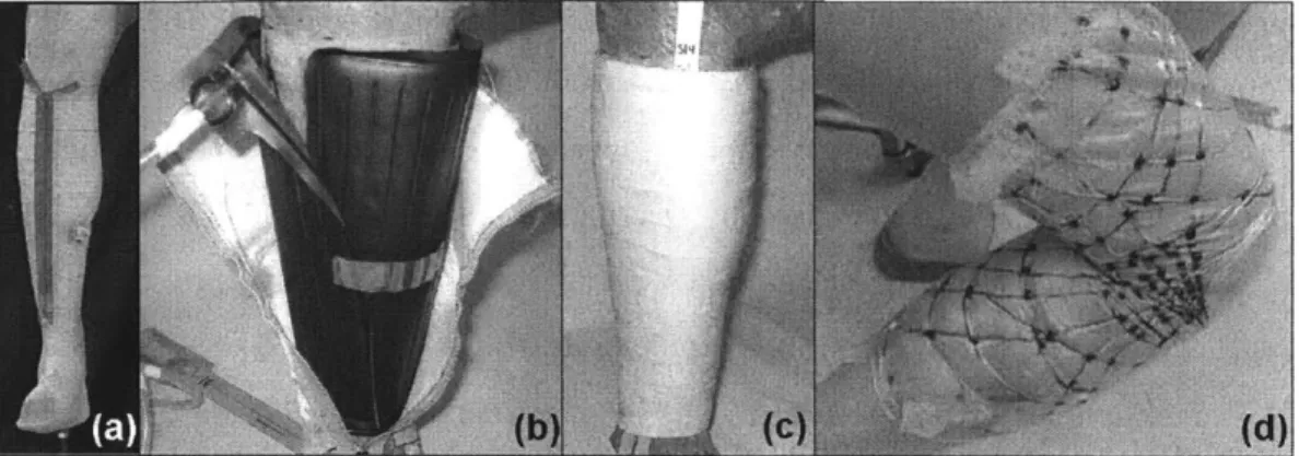
lon-gitudinal zipper for quick donning and doffing; (b) multi-channel pro-totype showing inner multi-channel inflation layer in black and white sailcloth restraint layer in white; (c) paint-on urethane layer of open-cell foam prototype; (d) lines of non-extension prototype fabricated using inextensible Kevlar fibers. . . . . 35
3-1 (Left) Tekscan I-Scan Model 9801 sensor on calf. The sensor has been cut into six strips (labelled 1-6) to improve conformity to the curved leg surface. Being extremely thin, the sensor causes minimal interference when used for measuring pressure applied by an MCP garment to the
calf (right). . . . . 38
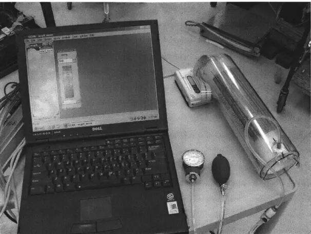
3-2 Tekscan I-Scan system undergoing calibration in the cylindrical cali-bration rig, consisting of two concentric rigid cylinders separated by a 10mm channel (right). A known load is being applied to the sensors by inflating a plastic bag inside the channel to a known pressure using the black hand pump (center), as measured by the rotary pressure gage (center). The pressure distribution being measured by the sensors is recorded and displayed graphically on the computer screen (left). . . 48
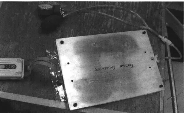
3-3 Flat-plate calibration rig consisting of two concentric aluminum plates separated by a 10mm channel in which the Tekscan sensor and inflat-able bladder are positioned. . . . . 49
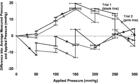
3-4 Difference between average measured pressure and applied pressure for I-Scan in the cylindrical rig. See text for full explanation. . . . . . 50
3-5 Difference between average measured pressure and applied pressure for I-Scan in the flat-plate rig. See text for full explanation. . . . . 50
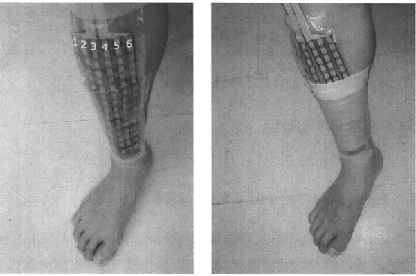
4-1 (a) Subject wearing detached bands prototype from ankle to thigh. (b) I-Scan sensors placed on calf anterior, with the sensor columns 1-6 defined as shown. The sensors on the anterior are positioned such that column 5 runs directly along the tibia, as indicated by the solid white line. (c) I-Scan sensors on calf posterior. . . . . 58
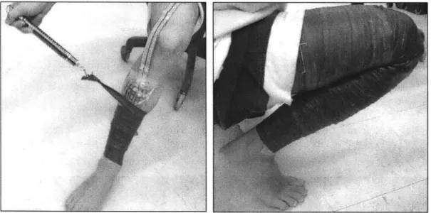
4-2 (a) Elastic bindings being donned over Tekscan sensors, with a spring scale being used to control the wrapping tension. (b) Subject demon-strating a deep knee squat while wearing elastic bindings. . . . . 61
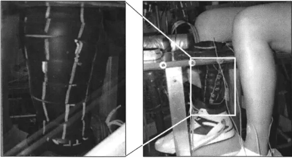
4-3 (a) Alignment marks along the length of the elastic bindings. (b) Alternate view of the alignment marks on bindings worn by a test subject in the low pressure leg chamber. . . . . 62
4-4 (a) Neoprene rubber elastic bindings showing custom-measured align-ment marks. (b) The 100mm-diameter rigid plastic cylinder used as an idealized model of a human leg, showing both longitudinal alignment lines (eight total, spaced 45' apart) and alignment spirals. The longitu-dinal lines align with the marks drawn on the bindings in (a) while the spirals guide the edges of the bindings as they are wrapped around the cylinder. (c) Binding being wrapped around the test cylinder, guided by both the alignment lines and spirals. In these experiments the re-quired binding strain was typically 100%, as illustrated, to achieve the desired 26.7kPa (200mmHg) pressure on the 100mm diameter cylinder. (d) Tekscan I-Scan sensors were placed on the cylinder to measure the pressure distribution generated by the bindings on the cylinder. . . . 67 4-5 (a) Elastic binding marked with centerline for use in a double-wrapped
cylinder. (b) Binding being "double-wrapped" around the cylinder. Each wrap is guided by the centerline on the binding rather than the
alignment spiral on the cylinder. . . . . 68 4-6 Series average pressure P generated by various MCP prototypes on
the test cylinder, except where 'anterior' or 'posterior' are stated, in which case the test object is the anterior or posterior of a human calf,
as described in the text. 'DB' = detached bands; 'EB1' and 'EB2' = elastic bindings phases 1 and 2 respectively; 'DW' = double wrap. 'Lines' refers to the longitudinal alignment lines and 'spiral' refers to the alignment spirals (Figure 4-4(b)). Dotted lines indicate the target pressure Pt for that prototype. Error bars show standard deviation S of of the average pressure; these bars are not available for DB and EBi
as only one snapshot, not ten, was measured for these prototypes. . . 71 4-7 Non-uniformity s in the pressure distribution generated by the elastic
bindings and other MCP prototypes. The labels 'DB', 'EB1' etc are defined in Figure 4-6. Note that the data for DB and EBI are for one snapshot only, not ten. . . . . 72
4-8 (a) Reference line from ankle to knee on inner surface of right calf. (b) and (c) Alignment lines on the front and outer calf surface (see text for full description). . . . . 76
4-9 Sample spreadsheet used to calculate alignment mark spacing and width changes for elastic bindings. The strain, alignment mark sep-aration and width columns are dependent on the test subject's calf circumference (second column from left) as well as the material prop-erties of the binding (not shown). . . . . 77
4-10 Pantyhose used to rapidly replicate the alignment lines and spirals on the leg. Here the subject is preparing for an experiment in the low pressure chamber (Chapter 6) as evidenced by the Tekscan sensor and black-colored chamber seal on the knee. . . . . 78
4-11 (a) Bladder layer of hybrid foot garment with bulkhead fitting imme-diately below the ankle-height blue line. (b) The bladder layer inside a standard athletic shoe, which acts as the restraint layer. The shoe prevents the bladder from expanding outwards, thus directing the infla-tion inwards onto the wearer's foot. (c) Hybrid foot garment providing MCP on a test subject's foot during low pressure leg chamber experi-ments described in Chapter 6 (reproduced from Figure 4-3). . . . . . 81
6-1 (a) Side view of subject with unsuited right calf exposed to underpres-sure inside the low presunderpres-sure leg chamber. The subject is wearing a blood pressure cuff (left arm), heart rate monitor (with data-logging watch on left wrist), temperature sensors on the front and back of the calf on both lefts (white wires) and the hybrid foot garment, as described in the text. (b) Front view of the setup shown in (a). . . . 93
6-2 Protocol for the unsuited and suited experiments described in this ch apter. . . . . 95
6-3 Test duration by subject and phase. All tests were terminated at the subject's request unless stated. *Subject terminated test early due to gradual loss of pressure in MCP foot garment. **Observer terminated test due to uncertainty regarding the condition of the suited calf. It was feared that since the subject had a very high pain threshold, he might not report any feelings of discomfort sufficiently early to pre-vent potential adverse effects. In this suited experiment, the calf could not be observed as it was concealed from view under the elastic bind-ings; the test observer therefore terminated the test as a precautionary measure, despite the subject's insistence that he felt fine (as indicated by the low level of discomfort). #Test observer terminated test after observing swelling or slight blistering on the calf inside the chamber. . 97
6-4 Subjective discomfort in unsuited tests. Black triangles marked with subject number (0-4) indicate the point at which that subject's test terminated. All tests were terminated at the subject's request unless stated. #See note in Figure 6-3. . . . . 98
6-5 Subjective discomfort in suited (Phase II) tests. Black triangles marked with subject number (0-4) indicate the point at which that subject's test terminated. *See note in Figure 6-3. **See note in Figure 6-3. . . 98
6-6 Series average pressure P generated by elastic bindings on the calf ante-rior during suited tests, by subject (blue bars). The pressure generated by the bindings on rigid test cylinders is reproduced from Figure 4-6 for comparison (red bars). Error bars show standard deviation S of of the average pressure. Numbers within bars show the number of pres-sure snapshot meapres-surements used to calculate P and S. Dotted lines indicate the target MCP Pt to which the bindings were designed; the 30kPa (225mmHg) target for the bindings used by the test subjects is equal to the gas pressure inside the Space Shuttle EMU. . . . . 99
6-7 Series standard deviation 3 in the pressure distribution generated by elastic bindings on the calf anterior during the suited tests, by sub-ject (blue bars). 3 for the pressure generated by the bindings on rigid test cylinders is reproduced from Figure 4-7 for comparison (red bars). Numbers within bars show the number of pressure snapshot measure-ments used to calculate . . . . . 99 6-8 Change in heart rate during unsuited tests, normalized to baseline
heart rate during ambient conditions. Black triangles indicate test termination point for the individual subject, as before. . . . . 101 6-9 Change in heart rate during suited tests, normalized to baseline heart
rate during ambient conditions. Black triangles indicate test termina-tion point for the individual subject, as before. *Baseline measured on unsuited subject, as discussed in text. . . . . 101 6-10 Change in systolic blood pressure during unsuited tests, normalized to
baseline pressure during ambient conditions. Black triangles indicate test termination point for the individual subject, as before. . . . . 102 6-11 Change in systolic blood pressure during suited tests, normalized to
baseline pressure during ambient conditions. Black triangles indicate test termination point for the individual subject, as before. *Baseline measured on unsuited subject, as discussed in text. . . . . 102 6-12 Change in diastolic blood pressure during unsuited tests, normalized
to baseline pressure during ambient conditions. Black triangles indicate test termination point for the individual subject, as before. . . . . 103 6-13 Change in diastolic blood pressure during suited tests, normalized to
baseline pressure during ambient conditions. Black triangles indicate test termination point for the individual subject, as before. *Baseline measured on unsuited subject, as discussed in text. . . . . 103
6-15 Change in skin temperature during unsuited tests, with 0 being the average baseline temperature during ambient conditions. ' and 'R' refer to left (out-of-chamber) and right (in-chamber) calves respec-tively. Figure excludes temperature data for the right calf of Subject 4 as the temperature sensors on this calf became loose, as explained in text. Error bars have been removed for visual clarity. Black triangles indicate test termination point for the individual subject, as before. . 105
6-16 Data for right (in-chamber) calf of Figure 6-15 by subject. . . . . 105
6-17 Change in skin temperature during suited tests, with 0 being the aver-age baseline temperature during ambient conditions (OmmHg chamber pressure). 'L' and 'R' refer to left (out-of-chamber, unsuited) and right (in-chamber, suited) calves respectively. Figure excludes majority of temperature data from Subject 1 (see Figure 6-18)that was lost during a computer crash at the conclusion of the test. Error bars have been removed for visual clarity. Black triangles indicate test termination point for the individual subject, as before. *Baseline measured with
unsuited subject, as discussed in text. . . . . 106
6-18 Data of Figure 6-17 by subject. The majority of temperature data from Subject 1 was lost during a computer crash at the conclusion of the test. Dotted line indicates end of unsuited baseline measurement
at 6 m inutes. . . . . 107 17
6-19 Typical front and back views of the calves after a suited chamber test. The right calf that was suited during the chamber test appears slightly swollen compared to the left calf. The horizontal indentations on the suited calf are areas where bindings unintentionally overlapped to pro-duce excessive MCP - very similar to foot and ankle indentations that naturally occur when socks are worn for several hours. The circular indentation on the calf posterior (black circle, right) was made by the skin temperature sensor. All these observable effects were temporary and naturally disappeared within several hours after the conclusion of
the test. ... ... 110
A-1 Soft cylindrical test rigs: (left) test rig intended for use in the elastic bindings tests; (right) calibration rig. . . . . 122 A-2 Difference between average measured pressure and applied pressure for
List of Tables
2.1 Summary of engineering requirements for an MCP spacesuit (adapted
from [3].) . . . . 29
2.2 Description and performance of previous MCP garments. It is difficult to directly compare spatial pressure variation and mobility across dif-ferent prototypes due to the difdif-ferent ways in which they are reported in the literature. "N/A" means "not available". . . . . 33 3.1 Summary of I-Scan accuracy metrics. . . . . 42 5.1 Summary of overpressure studies reviewed in this section. *Note:
Gar-ments are designed to provide 30mmHg; actual pressure not measured **With 5 minutes of pressure ramp-up and ramp-down. . . . . 86 5.2 Summary of underpressure studies reviewed in this section. *For 2-3
weeks prior to surgery. . . . . 88 6.1 Subject characteristics. *Calf circumference in ambient conditions. . 92
Chapter 1
Introduction
One of the key requirements of human planetary surface exploration is a spacesuit that enables astronaut locomotion. Since planetary traversal will involve loping, climbing, squatting and other locomotive activities, the mobility of spacesuits used for planetary traversal must greatly surpass that provided by any current or previous spacesuit.
Mechanical counterpressure (MCP) has been proposed as a technique for en-hancing astronaut mobility as well as offering reduced mass, lower profile, improved safety and numerous other advantages for planetary EVA [4]. In a MCP-based space-suit the body is pressurized using elastic tension in a skin-tight garment rather than by the gas in a traditional spacesuit. There have been numerous attempts in the last 35 years to create MCP spacesuits [3]; however, these have either been hindered by operational difficulties [1] or have only focused on creating MCP on small anatomical areas such as the hand [5, 6, 7, 8, 9].
The Bio-Suit System being developed at MIT's Man Vehicle Laboratory leverages new concepts and technologies to overcome obstacles encountered in previous MCP designs [10]. In particular, Bio-Suit subsystems are conceived to allow the explorer the same ease of use as ordinary clothing; eventually, the overall system is envisioned to provide a "second skin" capability, possibly incorporating biomechanic and cybernetic augmentation for enhanced human performance during planetary exploration.
This thesis describes the design and implementation of novel MCP concepts for 21
the Bio-Suit System. Two concepts known as the detached bands and elastic bindings were initially developed and tested in ambient conditions on a human leg. The elastic bindings permitted greater mobility than the detached bands and were also more comfortable and easier to don; however, the pressure distribution generated by the bindings on the leg was insufficiently uniform from a physiological perspective.
The bindings design was therefore refined and exhaustively tested on a cylindrical
surface - an idealized model of the human leg - to improve the uniformity of the
MCP it generated. Once the improved design was adapted for use on a human leg, five subjects wore custom-made bindings on their right calf and exposed the suited calf to -30kPa (-225mmHg, -0.3atm) for over an hour - a greater magnitude and longer
duration of underpressure than previous MCP garment tests - to demonstrate the
effectiveness of the bindings as a pressure garment. To further quantify the efficacy of the bindings in protecting the wearer against underpressure, changes in heart rate, skin temperature and blood pressure were recorded during the suited experiments and compared to the physiological response induced when an unsuited calf is exposed to underpressure.
This thesis is therefore structured as follows:
Chapter 2 discusses the motivation for MCP-based spacesuits and their potential
advantages over traditional gas-pressure spacesuits. The chapter reviews previous efforts to develop partial- or whole-body MCP prototypes and provides an overview of the Bio-Suit System.
Chapter 3 reviews the accuracy of the Tekscan I-Scan pressure measurement
sys-tem and describes experiments performed to quantify their accuracy on a cylindrical
surface - an idealized leg model, as mentioned earlier. The I-Scan sensors are one
of the most important means of measuring the performance of the MCP prototypes discussed in Chapter 4 and 6; these experiments were thus essential for interpreting the results of these chapters.
Chapter 4 describes the process by which the detached bands and elastic bindings
prototypes were designed, fabricated and preliminarily tested. As mentioned above, the elastic bindings demonstrated the best performance and were thus chosen for use
in subsequent physiological experiments.
Chapters 5 and 6 then describe the physiological effects of using the elastic bindings as a pressure garment. Chapter 5 provides context and background by reviewing the physiological implications of localized pressure variations that occur when using MCP in place of the gas pressure in a traditional spacesuit to pressurize the body surface. Finally, Chapter 6 describes experiments in which five subjects wore the elastic bindings prototype in a low pressure leg chamber for an hour or more. These demonstrated the bindings' capability to protect the leg from under-pressure and to mitigate physiological changes that occur with unprotected exposure to underpressure.
Chapter 2
Literature Review
2.1
Mechanical Counterpressure (MCP) Spacesuits
2.1.1
Motivation
One of the key requirements of human planetary surface exploration is a spacesuit that enables astronaut locomotion. Unlike microgravity EVA, which involves limited translation performed almost entirely with the hands and arms or via a robotic manip-ulator, future planetary surface EVA will require locomotion, long traverses, climbing, and extensive bending. These activities place new demands on spacesuit mobility and dexterity, especially in the lower body, that can only be attained by implementing designs that facilitate natural locomotion and minimize energetic expenditure.
The mobility permitted by future planetary spacesuits must therefore greatly sur-pass the mobility provided by current and previous spacesuits. High joint torques in the Apollo lunar suits forced astronauts on the Moon to walk with a considerably altered "bunny hop" gait to compensate for reduced knee and hip mobility [11], and hindered their ability to kneel or bend over to perform simple tasks such as picking up rock samples or performing a close-up inspection of the lunar surface. The cur-rent Space Shuttle Extravehicular Mobility Unit (EMU) and Russian Orlan suit are designed for work in weightlessness where lower body rigidity is actually beneficial in reducing the metabolic cost of producing counter-torques for body stabilization
during microgravity EVAs; however, this rigidity and the substantial mass ( 130 kg) of the EMU and similar gas pressurized spacesuits make these systems inadequate for planetary surface locomotion and exploration mission tasks [10].
Mechanical counterpressure (MCP) was first proposed by Annis and Webb in the late 1960s [12, 1] to greatly enhance astronaut mobility and dexterity, as well as offer improved safety and other advantages for planetary EVA. In a MCP-based spacesuit, the body is pressurized using elastic tension in a skin-tight garment rather than by the gas in a traditional spacesuit. Such a garment is conceptually similar to the compression garments worn by burn victims or patients with varicose veins and other circulatory problems; the challenge, however, is that the pressure that an MCP garment must generate is an order of magnitude higher than typical compression garments, as discussed in Section 2.1.2. The conceptual elegance of MCP not only has the potential to increase mobility but also simplify life support system design, reduce the astronaut's energy expenditure in using the suit, and greatly diminish the risk of depressurization and other EVA hazards [4].
An alternative method of pressurizing the body is a hybrid concept combining both gas-pressure and MCP elements whereby pressurized fluid bladders transduce MCP to the body via an inextensible restraint layer, much like a fighter pilot's g-suit or a blood pressure cuff. Hybrid garments are not "true" MCP garments because they still rely on fluid to transmit the pressure to the skin; as such, they do not enjoy many of the benefits inherent in an elastic-only' MCP garment. Most importantly, a hybrid garment, like a traditional gas-pressure suit, would suffer a loss of pressure that immediately propagates over the entire body in the event of a puncture anywhere on the suit; in contrast, loss of pressure in an elastic-only MCP garment would be limited to the region immediately around the puncture [4].
Hybrids are discussed in this thesis as they are relatively easy to develop and have been useful stepping stones for illustrating the practical and physiological issues associated with using MCP (Section 2.1.3). However, it cannot be over-emphasized
'In this thesis, an "elastic-only" MCP garment is defined as as one that does not use fluid to transmit pressure; it does not necessarily consist of an elastic material.
that a hybrid's reliance on fluid pressure prevents it from enjoying the safety and other benefits inherent in an elastic-only MCP garment; this, combined with other reasons2
, leads us to believe that operational MCP spacesuits of the future should avoid use of the hybrid concept as much as possible.
2.1.2
Engineering Requirements
Before reviewing previous MCP-based spacesuit development efforts it is necessary to discuss the engineering requirements that suits must satisfy. The function of a spacesuit (this term being used interchangeably with "EVA system") is to protect the wearer from the extreme environment of outer space (Earth orbit) or a planetary surface (Moon or Mars). The spacesuit must provide oxygen, pressurize the body surface with the same pressure as the breathing pressure, maintain the body at a comfortable temperature, and protect the body from radiation, micrometeorites and other hazards.
The MCP garment is only one of many spacesuit subsystems. Its function is primarily to pressurize the body surface, but it may also simplify thermal control by allowing the user to sweat through the garment if it is made of a porous material [1, 4]. Bio-Suit research to date, including this thesis, has focused on the pressurization function and assumes that other subsystems are modularly added to perform the thermal, radiation and other functions of the spacesuit [4, 13]. With this in mind, it is now possible to discuss the requirements for the pressurization function to be fulfilled by the MCP garment (sometimes referred to as a "pressure layer".)
First, the garment must apply MCP on the body that is equal to the pressure of the gas that the astronaut is breathing. We have assumed this to be 30kPa (225mmHg, 4.4psi) as this is the pressure of the pure oxygen atmosphere within the Shuttle EMU
2
Hybrids do have a few inherent advantages over elastic-only MCP garments. The level of MCP they produce on the skin can easily be adjusted by varying the fluid pressure; furthermore, the MCP distribution tends to be more uniform than an elastic-only MCP suit as the pressure inside the fluid bladder is already perfectly uniform. However, the pressure distribution in a gas-pressure suit is
already controllable and even more uniform than that produced by a hybrid garment since the former
has no bladder confounding the pressure transmission from fluid to body surface. Considering this in conjunction with the aforementioned loss-of-pressure aspect, one might thus argue that hybrids suffer the major disadvantages inherent in both gas-pressure and MCP-only suits.
as well as the minimum oxygen pressure required for normal oxygen diffusion, or normoxia (with some safety margin [14]). Note, however, that a higher breathing pressure and corresponding MCP would be highly beneficial for EVA operations be-cause it would substantially reduce pre-breathe times; in fact, a suit producing 55kPa (412mmHg, 8.Opsi) MCP would eliminate the need for pre-breathe altogether in a spacecraft at sea level ambient pressure (101.3kPa, 760mmHg, 14.7psi) [14], which is the pressure used on the ISS and Shuttle for most operations. In short, the garment must produce at least 30kPa MCP but higher pressures up to 55kPa are desirable3.
For hybrid garments, the requirement must be stated differently since the MCP applied by a hybrid garment varies with the pressure in its fluid bladder. Like a traditional gas-pressure spacesuit, this fluid pressure must be minimized in order to maximize the mobility of the hybrid garment whilst satisfying the 30kPa oxygen pressure mentioned above. The hybrid must therefore transform as much fluid pres-sure into MCP as possible, but it is inherently impossible for the MCP to be higher than the fluid pressure. As such, the requirement for a hybrid garment is that the MCP-to-fluid pressure ratio should be as close to the maximum value of 1 as possible.
As well as being at least 30kPa, it is extremely important that the applied MCP must be as uniform as possible to avoid adverse physiological effects such as bruising or edema that would be caused by spatial pressure variations across the body surface, as discussed in Chapter 5. Trevino and Carr [16] conservatively estimate that variations of less than 1.6kPa (±12mmHg) are unlikely to produce edema or restrict capillary blood flow, but are not certain as to the minimum magnitude or duration of variation that will produce edema or other adverse effects. This thesis has used ±12mmHg as the design requirement.
Similarly, the garment must avoid exposing large areas of the skin to the exter-nal (low pressure) environment, unintentioexter-nally or otherwise, because such exposure would create a spatial pressure variation between the exposed and unexposed areas that is as great as the applied MCP. However, the garment should still be porous in
3
See Gernhardt [15] for a far more detailed discussion on selection of breathing pressure and breathing gas composition.
order to allow the wearer to sweat, as discussed above. Webb showed that areas of skin as large as 1mm2
can be exposed to vacuum without adverse effects due to the inherent tensile strength of human skin [12]. We have thus included this maximum exposure limit in the requirements, but it may be possible to expose larger areas without unduly adverse effects'.
The mobility requirement has previously been defined by stating the maximum torque required to bend a joint to a specified position [3]. A simpler method is to ask whether the wearer can comfortably initiate and maintain a deep knee squat using only his/her body weight - a fundamental requirement for planetary exploration that, as mentioned in Chapter 1, the Apollo lunar suits were unable to satisfy.
Finally, the number and frequency of EVAs on planetary missions will be orders of magnitude higher than that required to complete the ISS [11]; it would be impractical for the MCP garment to require as much pre-EVA preparation time as the EMU or Orlan. As such, we require that the wearer should be able to don or doff the suit in less than ten minutes without any assistance [10].
The next section reviews previous MCP development efforts using the aforemen-tioned requirements (summarized in 2.1) as performance metrics.
Function Requirement
For elastic-only suits, apply at least 30kPa (225mmHg, 4.4psi) of average pressure at body surface. For hybrid garments, achieve
Pressure a 1:1 ratio of MCP-to-fluid pressure.
Production No more than 1.6kPa (±12mmHg) spatial variation in pressure [11].
Locally expose no more than 1mm' skin surface area to vacuum [1].
Mobility Permit wearer to initiate and maintain deep knee squat without
undue discomfort, using only body weight.
Operations Don and doff in less than 10 minutes without assistance.
Table 2.1: Summary of engineering requirements for an MCP spacesuit (adapted from [3].)
4
This is indirectly discussed in the literature review of Chapter 5.
2.1.3
Previous MCP Garments
Annis and Webb were the first to develop an MCP garment in the late 1960s
[1].
Their Space Activity Suit utilized seven layers of highly elastic material in order to pressurize the body surface, while a bubble helmet and chest bladder provided ade-quate breathing pressure (Figure 2-1). While the SAS initiated the MCP concept and demonstrated advantages of mobility, low energy costs and a simplified life support system, the difficultly in donning/doffing the SAS was the largest limitation; NASA subsequently did not pursue MCP suit development.Since then, however, several researchers have sustained the idea of MCP suits. In 1983 Clapp designed and tested an MCP glove and compared its performance to the A7L-B Skylab-era gas pressure glove [5]. Subjects who tested the elastic "skinsuit" glove in a partial vacuum of -24kPa (-180mmHg) for 30 continuous minutes5 retained 90% of bare-skin finger mobility, compared to 30% mobility in the A7L-B gas pressure glove. Slight edema occurred over the palm of the hand after 30 minutes of wearing the glove in the partial vacuum, but no other health problems were observed.
In 2002 Korona et al developed a hybrid gas elastic glove (Figure 2-1) and com-pared its performance to a 4000-Series EMU glove, finding that the hybrid slightly outperformed the EMU glove in both mobility and perceived exertion levels [2]. More recently, Tourbier, Tanak et al [6, 7] examined the physiological effects of elastic MCP gloves using an a skintight elastic design augmented with an inflatable layer for the dorsum (back surface) of the hand. The glove produced the desired 27kPa (200mmHg) of MCP on the dorsum and finger regions. However, the pressure on the palm, which was not pressurized by a bladder, was significantly lower at 9kPa (70mmHg, 1.4psi) as the elastic material stretched over the palm concavity and was thus unable to exert pressure on it. Even so, the glove prevented the blood flow increase, tissue edema and finger swelling that occurred on a bare hand subjected to similar levels of un-derpressure, and thus provided evidence that the glove could protect the user from physiological effects of underpressure.
5All pressures quoted in this thesis are gauge pressures - i.e. pressure above the absolute sea-level atmospheric pressure of 101.3kPa.
Figure 2-1: (Left) Annis' and Webb's Space Activity Suit [1]. (Right) Hybrid elastic glove of Korona et al [2].
The Tanaka group subsequently developed an elastic MCP sleeve for the full arm [9]. The pressure produced by the sleeve varied from 21kPa (160mmHg) at the forearm and upper arm to 31kPa (230mmHg) at the finger, dorsum of hand, and wrist. Despite the variations in pressure, the sleeve prevented adverse changes in skin blood flow and skin temperature during partial vacuum tests, and enabled sub-jects to tolerate underpressures of up to -20kPa (-150mmHg) for 5 minutes. These physiological results are discussed in further detail in Chapter 5.
In summary, the aforementioned efforts' have demonstrated the potential for MCP suits to provide considerably greater mobility and reduced metabolic cost compared to gas-pressure spacesuits; furthermore, they have provided preliminary evidence that
6
nterestingly, the Soviets also made significant attempts to develop MCP suits [17, 18]; details of the program appear to be classified, but we have been told that the efforts were abandoned due to operational and practical difficulties similar to those experienced by the US-based researchers described above.
MCP can be realized without adverse physiological effects. However, these designs have been limited by one or more factors, particularly difficulty in donning and doffing, a non-uniform pressure distribution, and insufficient pressure on body concavities. Furthermore, their mobility is still somewhat less than that of an unsuited human. Table 2.2 compares the performance of these systems.
2.2
Bio-Suit: An MCP-based EVA System
The Bio-Suit System being developed by MIT's Man Vehicle Laboratory (MVL) is a MCP-based EVA system for planetary exploration that leverages new concepts and technologies to overcome obstacles encountered by previous MCP suits [10]. In particular, Bio-Suit subsystems are conceived to allow the explorer the same ease of use as ordinary clothing (Figure 2-2); eventually, the overall system is envisioned to provide a "second skin" capability, possibly incorporating biomechanic and cybernetic augmentation for enhanced human performance during planetary exploration.
Bio-Suit development has progressed along three major streams: definition of Bio-Suit System requirements, prototype development and testing, and physiological considerations of MCP and spacesuit simulation for planetary missions [19]. This thesis contributes to all three streams, with a focus on prototype development and physiological considerations.
The requirements definition work is motivated by the fact that the pressure layer of the Bio-Suit System is skin-tight and is envisioned to provide a "second skin" capability. It is therefore critical to understand the detailed stretching and deforma-tion of human skin as well as the changes in volume, surface area and shape that occur during body movement, or locomotion. MVL has thus developed techniques for quantifying these changes using 3D laser scanning and digital image correlation and has subsequently demonstrated these techniques on a human leg at different joint angles [3].
Prototype development has been the primary focus of Bio-Suit research, the
de-P 0 -(D S 0 c K S0
-D
D~
*0 (D~
0 (D P p~CD Cn CIA: CADTarget Average MCP spatial Donning
Group Hybrid? body Description MCP variation time Mobility
area. (mmflgl
A(aim
)J
pTprLomAnnis and No VAole FuI-b3ody elastic suit consisting of Up to N/A two Approx. halfway between that
Webb (1971) body up to six skintight Spandex layers 170mnHg of unsuited and suited human
m rn198)
N H-land SkWnt qbve N N/A N/A 90% ofbare handorona e Yes Hand Hybrid glove N/A N/A N/A Approx 50% of bare handl
(2002) ____________________
Tourb;er .rqtgoeagmetdwt 0
Waldie etal Partial Hand Sn tg augmentg 24' NWA Not measured
(2021 air bladder on hanid dorsum 2l3nin ? 4'N/ otmesue
Tanaka eta! a
~
al Hand Skintight glove and arm sleevea(2003) and arm ugmened with air bladder on 173 1f N/A Not measured hand dorsun 222mmng
Pitts (2003) Yes Lower Single-channel hybrid ~1:1*d 2-' <Ss
Pitts (2003) yes Le Mutihannel hybrid ~2-1 WA 2min per ca Not applicle (garment does
le notcover knee joint)
Pitts (2003) Yes Lower Spray-on urethane layered foam -1:1 N/A 2niin per calf
15nin; two
Bethke (2005) Yes Full leg Spray-on urethane layered foam -3:1A N/A assistants Knee bends limited to 90*
Bethke (2006) No Ful leg Lines of non-extension 50-62* N/A -30s ds fort when knee
Notes
a. Measured only at a few discrete points (rather than a pressure distribution map) using inflatable bladder between garment and joint,
b, Measured using Tekscan I-Scan sensors
c. Measured using Tekscan I-Scan sensors; palm pressures for this prototype that were extremely low in the glove-ony prototype (above) not reported.
d. Hybrid bladder input-output pressure ratio, as descibed in text.
e. Excluding inside thigh where pressure ratio was -20:1.
f. Standard error from average. g. RMS deviation from row-means.
Figure 2-2: (Left) Artist's concept of an operational Bio-Suit System, envisaged to be far lighter and lower profile than current gas-filled spacesuits. (Right) An astronaut on Mars is depicted donning the Bio-Suit MCP pressure layer (1). A lightweight life support system (5) supplies breathing gas into the helmet (2) and possibly through elastic tubes to hybrid MCP glove and boots (3). A hard upper torso (4) on top of the MCP layer provides a structural foundation on which the life support system and other suit system elements can be mounted. Images courtesy of Cam Brensinger.
veloping comfortable, high-mobility prototypes that can protect the wearer from the effects of underpressure. MVL has concentrated on developing prototypes for the lower body due to the relative lack of leg mobility in current and previous space-suits [10] and to demonstrate a revolutionary locomotion capability for exploration missions in partial gravity environments; however, the leg prototypes are directly applicable to the arm with relatively few modifications.
Pitts developed two types of hybrid prototype for the lower leg and used these to demonstrate the basic feasibility of MCP and gain practical insight into using MCP garments [14]. The first featured one or more longitudinal channels between the skin and garment that expand as it fills with gas (Figure 2-3(a) and (b)), similar to some partial pressure suits for fighter pilots (Bethke [3], p22.) The second was a highly innovative design comprising an inflatable foam layer sealed by spray-on urethane
Figure 2-3: Previous Bio-Suit prototypes: (a) single-channel prototype with longitu-dinal zipper for quick donning and doffing; (b) multi-channel prototype showing inner multi-channel inflation layer in black and white sailcloth restraint layer in white; (c) paint-on urethane layer of open-cell foam prototype; (d) lines of non-extension pro-totype fabricated using inextensible Kevlar fibers.
layers, the result being a skintight garment that conforms very well to the wearer's body shape (Figure 2-3(c)).
As mentioned earlier, however, the preferred approach is to pressurize the body using only elastic tension without relying on any form of fluid pressure. As such, MVL has also developed elastic-only prototypes based on several different concepts. Bethke [3] developed a leg garment patterned along the body's lines of non-extension (LoNE), empirical lines along the body surface that remain the same length as the body moves. The LoNE concept was originally proposed by Iberall in the 1950s for use as restraint layers of gas-filled pressure suits [20]; Bethke adopted the concept to develop a minimum energy-maximum mobility MCP prototype made of inexten-sible Kevlar fibers and demonstrated their ability to provide excellent leg mobility (Figure 2-3(d)).
Finally, there are several motivations for research into the physiological con-siderations of using MCP. First, a major problem with current and previous MCP prototypes is that the wearer must endure overpressure on one body part while the rest of the suit is being donned. This causes considerable discomfort even for gar-ments that can be donned or doffed in a few minutes; adverse physiological effects may occur if the donning time is longer than 20-30 minutes [1]. Additionally,
ing MCP suits for extended periods may induce some adverse effects on the body -for example, if the MCP generated on the body is not uni-form or does not match the breathing pressure. Previous research has measured changes in blood flow, skin temperature and other effects caused by wearing MCP garments and has provided some evidence that MCP can be realized without excessively adverse physiological effects [1, 9], as reviewed in detail in Chapters 5 and 6.
MVL research has extended these results by quantitatively considering the effects of pressure differentials between different parts of the body, as it is unlikely that an MCP suit will produce a pressure distribution as uniform as that in a gas pressure suit. Trevino and Carr derived a theoretical first-order estimate of the differential that can be supported by the cardio-pulmonary system without causing edema [16]. Carr has also begun developing non-invasive experimental methods for assessing edema in a human subject wearing an MCP garment using a thermal diffusion probe [21].
Chapter 3
Tekscan I-Scan Sensors for
Pressure Distribution
Measurements
3.1
Introduction and Motivation
The I-Scan Pressure Sensor System (Tekscan, South Boston MA) is used to measure the mechanical counterpressure distribution generated by Bio-Suit prototypes. The I-Scan system pressure sensor is a flexible printed circuit with individual sensing el-ements, or sensels, arranged in a rectangular array. Each sensel acts as a variable resistor in an electrical circuit; the resistance decreases as the applied pressure in-creases. Tekscan offers I-Scan pressure sensors in a wide variety of geometries; for Bio-Suit work, the most commonly used sensor has been the Model 9801 sensor con-sisting of 96 12.7mmx12.7mm (0.5"xO.5") sensels arranged in a 16x6 rectangular array (Figure 3-1).The 9801 sensor, in conjunction with the I-Scan software that controls its operation and collects its pressure measurements, will hereafter be collectively known simply as "I-Scan".
At first glance, the I-Scan system seems particularly appropriate for measuring MCP for several reasons. First, the sensors are extremely thin (0.1mm) and thus
cause minimal interference or pressure points between the garment and skin. The sensors can also measure the pressure distribution of a given area in real time, as opposed to many other thin sensors that can only take pressure measurements at a few discrete points, measure the mean pressure over the given area, or cannot make measurements in real time. Finally, the sensors can be cut into strips to increase their conformance to curved surfaces such as the leg.
Figure 3-1: (Left) Tekscan I-Scan Model 9801 sensor on calf. The sensor has been cut into six strips (labelled 1-6) to improve conformity to the curved leg surface. Being extremely thin, the sensor causes minimal interference when used for measuring pressure applied by an MCP garment to the calf (right).
However, when using the sensors to test Bio-Suit calf prototypes [13] the I-Scan measurements were suspected to be an inaccurate representation of the actual garment pressure. Most problematically, pressure spikes were observed at individual sensels that were 4-5 times higher than the pressure measured by surrounding sensels; these were almost undoubtedly false as they were not felt by the wearer and because there was no physical reason for the garment to produce such sharp and localized spikes. Additionally, minor pressure variations between the sensels could be observed even
under ideal loading conditions such as when the sensor was being calibrated between two flat plates, despite the sensor having been equilibrated before measurement to compensate for these variations. The I-Scan system also repeatedly exhibited 5-10% hysteresis, even during calibration, that was difficult to predict and to compensate for in field measurements. Finally, the sensors exhibited an extremely slow response time
- despite their 8Hz maximum sampling frequency - requiring more than a minute to correctly read a change in the applied pressure.
Before using the sensors to measure the MCP produced by Bio-Suit garments (Chapters 4 and 6) a literature review was undertaken to quantify their accuracy as determined by other I-Scan users (Section 3.2). This review also investigated the use of alternative pressure measurement systems to avoid the problems of the I-Scan sensors.
The experiments described in the literature review tested I-Scan accuracy on a flat surface; however, for Bio-Suit work the I-Scan sensors are being used on the curved surface of a human leg. A series of experiments was therefore performed to measure and compare the accuracy of the sensors on cylindrical and flat surfaces (Section 3.3.)
3.2
Literature Review
3.2.1
Accuracy of I-Scan Sensors
Tekscan [22] claims that the "overall"1 accuracy of the I-Scan system is
approxi-mately 10% and depends on the care taken by user to calibrate the sensors. However, they acknowledge that under non-ideal conditions I-Scan suffers further inaccuracies including:
" Temperature - for every deg F the calibration temperature differs from
appli-cation, the sensor reading will err by up to 0.25%.
" Creep - 3% per log time, depending on the duration of applied load during
calibration.
'However, "overall" is not clearly defined in the document.
* Hysteresis - up to 5%2.
* False pressure spikes when the sensor is crimped or wrinkled.
McWilliams [23] suggested that many of these errors are likely to be caused by sensor crimping. He therefore suggested that for pressure garment testing the subject should wear pantyhose to protect the sensor from moisture and shear against the skin and cutting the sensor into strips to improve its conformity to the curved surface of the leg. These countermeasures had already been previously attempted [14, 3] with little success; false pressure spikes could still be clearly observed. He also suggested putting conformal plastic plates between the sensor and skin to reduce crimping; however, this was unsuitable because it would alter the suit characteristics and pressure production. Wilson et al [24] quantified I-Scan accuracy by statically loading the sensors with a known pressure (1-7MPa) in an Instron testing machine between rubber-backed aluminum plates and showed that I-Scan measures the mean pressure with <10% error. They also loaded the sensor with two different loads to crudely determine how well I-Scan measured the local, as opposed to mean, pressure. In this case they found the error to be less than 1% - surprisingly better than that of the mean pressure. The authors acknowledged that the system displays other inaccuracies such as hysteresis and creep, which were deliberately minimized in this experiment, and that further inaccuracies may arise when measuring the asymmetrical geometry and changing compliance of human joints.
Matsuda et al [25] measured the accuracy of I-Scan sensors in measuring contact area and stress under ideal static loading conditions using an Instron machine and a circular steel indenter. Between the calibration loads the I-Scan overestimated contact area by about 10% but measured the applied force to within <5%, giving the system a better than 10% accuracy in pressure measurement under ideal conditions, similar to that reported by Wilson.
Mann et al [26] used I-Scan to measure the pressure provided by compression gloves and sleeves. In calibrating the sensors they determined that its accuracy in
2
measuring a 151b weight was 3%.
Kirstukas [27] measured the accuracy of I-Scan force measurements in repeated deforming use by applying 80 cycles of a 900N peak force using polyurethane and rubber indenter balls. Foam rubber up to 1" thick was placed between the sensor and load cell to simulate tissue between a patient's skin and skeletal frame. The author qualitatively claimed that I-Scan was accurate in measuring contact force if well calibrated. However, the sensor exhibited 5-10% creep as measured by calibra-tion coefficients as well as false pressure spikes when wrinkled, especially on thick substrates at lower contact pressures.
DeMarco et al [28] measured the accuracy of I-Scan sensors in measuring contact pressure and area by applying calibration loads of up to 2500psi to Tekscan Model 5051 sensors. Loads were transferred through a spherical joint adapted to a cylindrical Delrin peg with a rubber damping layer on the end of the peg; the sensor was placed between this damper and a smooth aluminum plate. They found that the Tekscan calibrated at three points had an mean pressure measurement error of over 11% while that of a sensor with eleven calibration points was about 4%. Unfortunately, Tekscan no longer offers the software to calibrate I-Scan with eleven points because it was found to be too time consuming for most users [23]; as such, Bio-Suit I-Scan measurements only use two calibration points (Appendix B).
McPoil et al [29] loaded F-Scan sensors (similar to I-Scan but designed specially for the foot) to 150kPa for 10min to test creep performance. The F-Scan exhibited 11.6% creep in a non-linear fashion.
Fregly et al [30] measured the magnitude of discretization errors in K-Scan sensors (K-Scan being a subset of I-Scan sensors designed for knee applications) by subjecting them to Hertzian and uniform pressure distributions. The measured errors were up to 4% for contact force and peak pressure and up to 9% for mean pressure and contact area. The authors suggested that discretization error was on the same order of magnitude as other sources of error (sensor insertion, pressure truncation) and should thus be considered when evaluating sensor accuracy. However, when compared to the results from other researchers (Table 3.1) Fregly's results suggest that the majority