HAL Id: hal-01629533
https://hal.archives-ouvertes.fr/hal-01629533
Submitted on 6 Nov 2017HAL is a multi-disciplinary open access archive for the deposit and dissemination of sci-entific research documents, whether they are pub-lished or not. The documents may come from teaching and research institutions in France or abroad, or from public or private research centers.
L’archive ouverte pluridisciplinaire HAL, est destinée au dépôt et à la diffusion de documents scientifiques de niveau recherche, publiés ou non, émanant des établissements d’enseignement et de recherche français ou étrangers, des laboratoires publics ou privés.
DESIGN OF AN OFFSHORE THREE-BLADED
VERTICAL AXIS WIND TURBINE FOR WIND
TUNNEL EXPERIMENTS
Sukanta Roy, Hubert Branger, Luneau Christopher, Denis Bourras, Benoit
Paillard
To cite this version:
Sukanta Roy, Hubert Branger, Luneau Christopher, Denis Bourras, Benoit Paillard. DESIGN OF AN OFFSHORE THREE-BLADED VERTICAL AXIS WIND TURBINE FOR WIND TUNNEL EXPERIMENTS. ASME 2017 36th International Conference on Ocean, Offshore and Arctic Engi-neering OMAE2017, Jun 2017, Trondheim, Norway. �hal-01629533�
Proceedings of the ASME 2017 36th International Conference on Ocean, Offshore and Arctic Engineering OMAE2017 June 25-30, 2017, Trondheim, Norway
OMAE2017-61512
DESIGN OF AN OFFSHORE THREE-BLADED VERTICAL AXIS WIND TURBINE FOR
WIND TUNNEL EXPERIMENTS
Sukanta Roy
IRPHE, Aix Marseille University, EOLFI 13288 Marseille, France
Email: sukantamech07@gmail.com
Hubert Branger
CNRS, IRPHE, Aix Marseille University 13288 Marseille, France Email: branger@irphe.univ-mrs.fr
Luneau Christopher
CNRS, Institut Pythéas- OSU 13288 Marseille, France
Email: christopher.luneau@univ-amu.fr
Denis Bourras
CNRS/MIO, Aix-Marseille University 13288 Marseille, France Email: denis.bourras@mio.osupytheas.fr Benoit Paillard EOLFI 75008 Paris, France Email: benoit.paillard@eolfi.com ABSTRACT
The rapid shrinkage of fossil fuel sources and contrary fast-growing energy needs of social, industrial and technological enhancements, necessitate the need of different approaches to exploit the various renewable energy sources. Among the several technological alternatives, wind energy is one of the most emerging prospective because of its renewable, sustainable and environment friendly nature, especially at its offshore locations. The recent growth of the offshore wind energy market has significantly increased the technological importance of the offshore vertical axis wind turbines, both as floating or fixed installations. Particularly, the class of lift-driven vertical axis wind turbines is very promising; however, the existing design and technology is not competent enough to meet the global need of offshore wind energy. In this context, the project AEROPITCH co-investigated by EOLFI, CORETI and IRPHE aims at the development of a robust and sophisticated offshore vertical axis wind turbine, which would bring decisive competitive advantage in the offshore wind energy market. In this paper, simulations have been performed on the various airfoils of NACA 4-series, 5-series and Selig profiles at different chord Reynolds numbers of 60000, 100000 and 140000 using double multiple streamtube model with tip loss correction. Based on the power coefficient, the best suitable airfoil S1046 has been selected for a 3-bladed vertical axis wind turbine. Besides the blade profile, the turbine design parameters such as aspect ratio and solidity ratio have also been investigated by varying the diameter and chord of the blade. Further, a series of wind tunnel experiments will be performed on the developed wind turbine, and the
implementation of active pitch control in the developed turbine will be investigated in future research.
NOMENCLATURE
α Angle of attack (°) θ Azimuthal angle (°) σ Solidity ratio
ω Rotational speed of the turbine (rad/s) ρ Density of air (Kg/m3)
λ Tip speed ratio, TSR AR Aspect ratio
ad Downstream interference factor
au Upstream interference factor
C Chord length (m)
CFD Computational fluid dynamics CD Coefficient of drag
CL Coefficient of lift
CN Normal force coefficient
CP Power coefficient
CPmax Maximum power coefficient
CQ Torque coefficient
CT Tangential force coefficient
DMST Double multiple streamtube FD Drag force (N)
FL Lift force (N)
FN Normal force (N)
FT Tangential force (N)
HAWT Horizontal axis wind turbine n Number of blades
R Radius of the turbine (m) Rec Chord Reynolds number
S Swept area (m2)
U∞ Free stream velocity (m/s)
Ud Downstream induced velocity (m/s)
Ue Equilibrium velocity between upstream and
downstream rotor disks (m/s) Uu Upstream induced velocity (m/s)
Uw Wake velocity (m/s)
VAWT Vertical axis wind turbine W Relative velocity (m/s)
INTRODUCTION
Since the energy crisis in early 1970s, the green and renewable energy sources have grabbed much attention in both industry and academic research. The adverse carbon emission effects of fossil fuels and lack of availability issues push the concern about the wind, water and solar energy alternatives.
Focusing on the wind energy conversion, there are two broad categories of modern wind turbines based on their rotational axis, namely horizontal axis wind turbine (HAWT) and vertical axis wind turbine (VAWT). Although, the HAWTs are dominating the wind energy market, in recent times, a renewed interest has been observed on VAWTs. Particularly, the recent growth in offshore wind energy market and the interest on decentralized power generation enhance the research possibilities on VAWTs. For offshore applications, the VAWTs offer distinct advantages such as energy conversion capability regardless of wind direction, good positioning of generator and gearbox below the turbine that gives a simpler and lighter structure, reducing the installation cost in offshore locations. Further, the structural stability at high-speed winds is another advantage of VAWT. The advantages of lower center of gravity, reduced machine complexity and better scalability to large sizes made it interesting for offshore applications, and several multi-megawatt offshore VAWT projects are currently underway [1]. However, since the VAWT has a rotational axis normal to the incident flow, the flow aerodynamics is more complicated than that of well-known HAWTs [2].
The modern lift-driven VAWT was invented by a French engineer GJM Darrieus in 1931 for both the “straight-bladed” and “eggbeater types [3]. However, up to early 1970s, there has been very less research on VAWTs. Afterwards, in last few decades, a number of studies have been reported on VAWTs for improving its performance [4]. The frontal view of a typical 3-bladed H-Darrieus type VAWT is shown in Fig. 1.
The wind turbine performance is often characterized by power coefficient and torque coefficient. The optimum operating condition for such a turbine depends on the aerodynamic force characteristics of the blade airfoil, turbine solidity, chord length, turbine radius, turbine height, blade twist angle and tip speed ratio. However, the investigations on the blade airfoils of VAWTs are far fewer than those have been carried out on the HAWTs, and the parametric investigation on
a wide range of designs is experimentally expensive and time taking procedure. In this context, Marten et al. [5] have developed a fast processing algorithm ‘QBlade’ based on double multiple stream tube (DMST) model as described in [6,7]. The application of DMST for performance prediction of the VAWTs were also observed in the studies of Beri and Yao [8], Biadgo et al. [9] and Wang et al. [10].
Figure 1. Frontal view of a 3-bladed Darrieus type VAWT
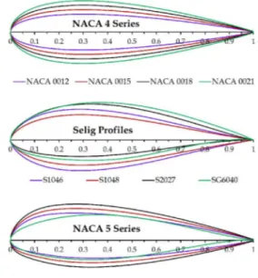
To improve the performance of VAWTs for offshore applications, the project AEROPITCH co-investigated by EOLFI, CORETI and IRPHE, has been developing and testing VAWT models through analytical, numerical and experimental approach. As a preliminary part of this project, a series of simulations have been performed on several blade airfoils (Fig. 2) using DMST model for designing a 3-bladed VAWT to be tested in the wind tunnel facility at chord Reynolds numbers (Rec) in the range 60000 to 140000. For wind tunnel model
testing, the selection of such a low Rec (order of104–105) can
be justified through Similitude scaling approach for Froude number and Reynolds number, as well explained in [11]. The approach was reported to be useful for model testing of large-scale real turbines operating at Rec in the order of 106.
The first objective is to select a suitable airfoil from NACA 4-series, NACA 5-series, and Selig profiles (Fig. 2). The next objective is to design the turbine with respect to a better aspect ratio (AR = H/D) and solidity ratio (σ = nC/2R) by varying the turbine radius (R) and blade chord length (C).
METHODOLOGY
The analysis performed in the present work are based on double multiple stream tube (DMST) model using QBlade v0.9 [5], developed for the VAWTs (particularly, Darrieus type). The first step for this analysis is to calculate the forces acting on the VAWT blades (Fig. 3).
Figure 3. Forces acting on the VAWT blades
The lift coefficient (CL) and drag coefficient (CD) are given
by: S U F C L L 2 5 . 0 (1) S U F C D D 2 5 . 0 (2)
where, ρ is the density of air and S is the blade swept area. The values of CN (normal force efficient) and CT
(tangential force coefficient) are calculated by:
sin cos D L N C C C (3) cos sin D L T C C C (4)
where, the angle of attack, α can be calculated from the azimuthal angle (θ) turbine radius (R), rotational speed (ω), relative velocity (W) and local induced velocity (Uu) [8]:
R U U u u cos sin tan (5)
The lift and drag characteristics of the different airfoils tested in the study have been obtained using XFOIL algorithm (integrated with open source code XFLR 5) at different chord Reynolds numbers (Rec). However, the calculation has been
kept to a small angle of attack that lies before and just beyond stall point to avoid the effect of separation and non-convergence. For the smooth operation with DMST, the polars of CL and CD obtained from XFOIL analysis have been
extrapolated to 360° angle of attack (Fig. 4) using the extrapolation method explained in [12].
Figure 4. Polar extrapolation to 360° angle of attack
The next step is to define the VAWT geometry for each of the airfoils in the QBlade blade design module using the extrapolated polar data at each chord Reynolds number. The chord length of each airfoil has been set to 0.09 m with turbine radius of 0.8 m and turbine height of 0.9 m.
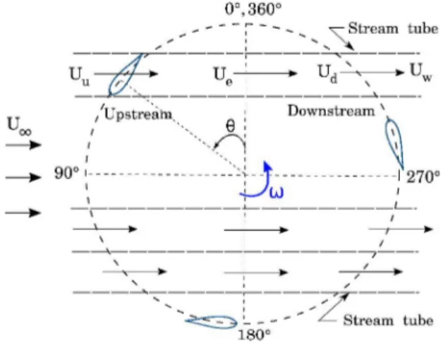
Following the design step, the simulations have been carried out for each of the airfoils. The double multiple stream tube model, as described in [6,7], is modeled by a pair of actuator rotor disks in tandem (Fig. 5), one at the upstream of the turbine rotation (0°-180°) and another at the downstream of the turbine rotation (180°-360°). Each of the turbine blades is discretized into number of elements, and the complete rotational cycle of each element is divided into steps of 5° [5]. The flow through the turbine blades is sub-divided into a large number of streamtubes. The different induced velocities are calculated at the upstream and downstream locations for each of the streamtubes. The effect of turbulence is neglected, and two-dimensional flow is assumed.
As the flow passes through a particular streamtube, the blades extract kinetic energy of the flowing fluid at the upstream and downstream locations, and thereby the velocity drops at each actuator rotor disk of each streamtube. The freestream wind velocity, U∞ models the velocities at each
section through consideration of interference factors au at the
upstream and ad at the downstream:
a U Uu u (6) a U Ue (2 u 1) (7)
a a U Ud d(2 u 1) (8) a a U Uw (2 d 1)(2 u 1) (9)
where, Uu is the induced fluid velocity at the upstream rotor
disk, Ue is the fluid velocity at the equilibrium plane between
upstream and downstream rotor disk, Ud is the induced fluid
velocity at the downstream rotor disk, and Uw is the fluid
velocity at the wake.
If au = 1, zero energy extraction from the flowing fluid,
and au = 0, the fluid brought to rest.
Figure 5. Streamtubes on VAWT rotation
The upstream and downstream interference factors are calculated for each height position based on the forces acting on their respective circular halves and integrated over the half-circular rotation. These factors are calculated using the blade element theory and momentum equation over each streamtube using the effect of CN and CT.
The torque coefficient (CQ) has been integrated over the
complete rotational cycle. The equations used in the present work for derivation of au, ad and CQ can be found in [5, 6, and
7]. The power coefficient (CP) has been obtained from CQ by:
Q
P C
C (10) where, λ represents tip speed ratio (TSR) of the turbine, given by: U R (11) VALIDATION
To validate the present methodology, a comparative study has been performed for a two-bladed Darrieus type VAWT using NACA 0015 airfoil (Fig. 6). The experimental data of Sandia laboratory [13] for 17 m diameter VAWT have been compared with the present study using DMST model with tip loss correction considering with and without the shaft gap. The comparative study shows a good validation of the present model, particularly tip speed ratio below 6. It is mainly due to
steady assumption in the DMST model, which could not predict well for unsteady flows at high tip speed ratios. Although the method has marginally over-predicted the results, the use of this methodology allows the flexibility to study a wide range of airfoils and turbine design parameters to obtain a suitable aerodynamic design of VAWT with significantly lesser computational cost. The obtained design can be further studied in detail through comprehensive CFD analysis.
Figure 6. Validation study for DMST VAWT model RESULTS AND DISCUSSION
In the present work, for a 3-bladed VAWT, several airfoils of NACA 4-series, NACA 5-series and Selig profiles (Fig. 2) have been tested at chord Reynolds numbers of 60000,100000, and 140000 for obtaining a suitable airfoil for the wind tunnel experiments under AEROPITCH project. The lift and drag characteristics of all tested models under each chord Reynolds number have been obtained with XFOIL aerodynamic tool, and extrapolated for a complete rotational cycle. DMST with tip loss correction method has been adopted for all the simulations to calculate the power coefficient of the VAWT. Further, the design parameters such as aspect ratio (AR = H/D) and solidity ratio (σ = nC/2R) have been tested at the above- mentioned chord Reynolds numbers.
Selection of Airfoil
The presented airfoils in this paper have been selected from a series of studies on various NACA 4-series, 5-series and Selig profiles. The top 4 airfoils in each category is demonstrated in the present paper. All the tested airfoils have been set to 0.09 m chord length with turbine radius of 0.8 m and turbine height of 0.9 m. For each case, the analysis has been carried out at TSR = 0 to 6 with step of 0.2.
At chord Reynolds number (Rec) of 60000, for NACA
4-series airfoils, as the thickness of the profile increases, a reduction in the operating range is observed (Fig. 7). At Rec =
60000, the peak performance coefficient (CPmax) of 0.32 is
observed for NACA 0015 at TSR = 3.8 among the tested NACA 4-series airfoils. NACA 0012, NACA 0018 and NACA
0021 have shown CPmax of 0.31 at TSR = 3.6, CPmax of 0.29 at
TSR = 3.8 and CPmax of 0.24 at TSR = 3.8, respectively. NACA
5-series seems not very interesting for VAWTs. Among the NACA 5-series airfoils NACA 63215 shown a CPmax of 0.28 at
TSR = 3.4 (Fig. 8). For VAWTs, at Rec = 60000, Selig profile
S1046 has shown a CPmax of 0.33 at TSR = 3.4, whereas, a
CPmax of 0.29 at TSR = 3.8 is calculated with S1048 (Fig. 9).
Figure 7. Variation of CP for NACA 4-series at Rec = 60000
Figure 8. Variation of CP for NACA 5-series at Rec = 60000
At Rec = 100000, an almost similar trend of CPmax is
observed for better airfoils as found at Rec = 60000. The values
of CPmax are obtained as 0.37, 0.37, and 0.36 for NACA 0015 at
TSR = 3.8, NACA 0018 at TSR = 3.6 and NACA 0012 at TSR = 3.8, respectively (Fig. 10). At this Rec, the values of CPmax for
NACA 23018, NACA 23015and NACA 63215 are obtained as 0.34 at TSR = 3.4, 0.34 at TSR 3.6, and 0.33 at TSR = 3.6, respectively (Fig. 11). The Selig profile S1046 has shown a CPmax of 0.38 at TSR = 3.4, whereas the nearest Selig profile
S1048 has shown a CPmax of 0.36 at TSR = 3.8 (Fig. 12).
Similarly, Figs. 13, 14, and 15 show the variations of CP at
Rec = 140000 for NACA 4-series, NACA 5-series and Selig
profiles, respectively. At Rec = 140000, NACA 0015 has given
a CPmax of 0.40 at TSR = 3.8. NACA 0018 and NACA 0012
has shown a similar peak magnitude of 0.39 at TSR = 3.8 (Fig. 13). At this Rec, the values of CPmax for NACA 5-series profiles
such as NACA 23015, NACA 23018, NACA 23021 and NACA 63215 are obtained as 0.37, 0.36, 0.35 and 0.36, respectively (Fig. 14).
Figure 9. Variation of CP for Selig profiles at Rec = 60000
Figure 10. Variation of CP for NACA 4-series at Rec = 100000
Among the Selig profiles, at Rec = 140000, a CPmax of 0.41
at TSR = 3.6 is observed for S1046 as compared to CPmax of
0.39 at TSR = 3.8 for S1048 (Fig. 15). From this comparative analysis at different chord Reynolds numbers, S1046 airfoil is obtained to be suitable for the project AEROPITCH.
Figure 12. Variation of CP for Selig profiles at Rec = 100000
Figure 13. Variation of CP for NACA 4-series at Rec = 140000
Figure 14. Variation of CP for NACA 5-series at Rec = 140000
Analysis of Aspect Ratio (AR)
The turbine aspect ratio (AR) is defined as ratio height of the turbine (H) to the turbine diameter (D = 2R). In this study,
the chord length (C) and turbine height (H) are considered constants as 0.09 m and 0.9 m. The aspect ratio has been varied by turbine radius R = 0.75 m, 0.5625 m, 0.45 m, 0.375 m and 0.32 m to obtain AR = 0.60, 0.80, 1.0, 1.20, and 1.40, respectively. All the simulations are carried out for a 3-bladed VAWT using S1046 at Rec = 60000, 100000, and 140000.
Figure 15. Variation of CP for Selig profiles at Rec = 140000
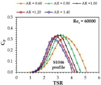
It has been observed that at low chord Reynolds number (Fig. 16), smaller ARs (<1) have higher CPmax than the higher
ARs (>1). At Rec = 60000, the peak CPmax of 0.34 has been
obtained with AR = 0.80 at TSR = 3.2, whereas, CPmax of 0.32
at TSR = 3.6, CPmax of 0.33 at TSR = 3.0, CPmax of 0.32 at TSR
= 2.8, and CPmax of 0.30 at TSR = 2.8 are obtained for AR =
0.60, 1.0, 1.20, and 1.40, respectively.
Figure 16. Effect of AR at Rec = 60000 for a 3-bladed VAWT
As Rec increases to 100000 (Fig. 17), the performance has
been increased with higher ARs. A CPmax of 0.45 is obtained at
TSR = 2.6 with AR = 1.20 in comparison to 0.44 (at TSR = 2.8), 0.44 (at TSR = 2.4), 0.43 (at TSR = 3.0), and 0.39 (at TSR = 3.4) with AR = 1.0, 1.4, 0.8 and 0.6, respectively.
Figure 17. Effect of AR at Rec = 100000 for a 3-bladed VAWT
With the further increase of chord Reynolds number at Rec
= 140000 (Fig. 18), the turbine performance gets even better. With AR = 1.20, a CPmax of 0.48 is calculated at TSR = 2.6. In
contrast, the values of CPmax obtained with AR = 0.60, 0.80,
1.0, and 1.40 are 0.41 (at TSR = 3.4), 0.45 (at TSR = 3.0), 0.47 (at TSR = 2.4) and 0.47 (at TSR = 2.8). Although, the variation of turbine performance with respect to change in AR is significant at different chord Reynolds numbers, however, it has been observed that the design with AR = 1.0 is more consistent at lower as well as higher chord Reynolds numbers. Thus, AR = 1.0 has been selected for the analysis of solidity.
Figure 18. Effect of AR at Rec = 140000 for a 3-bladed VAWT
Analysis of Solidity Ratio (σ)
It is one of the most important parameter for the VAWT design. It is defined as σ = nC/2R, where n is the number of blades, C is the blade chord length and R is the turbine radius. To select a better design for the project, the chord length has been varied as 0.03 m, 0.05 m, 0.07 m, 0.09m, 0.11 m, and 0.13 m; with turbine height (H) has been kept constant at 0.9 m, and AR = 1.0 is maintained for all the solidity test designs.
The variation in the chord lengths is resulted in solidity designs σ = 0.10, 0.17, 0.23, 0.37, and 0.43, respectively. All the designs are tested with Selig profile S1046. Figs. 19-21 show the variations of power coefficients at Rec = 60000,
100000, and 140000.
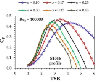
It has been observed that with solidity ratio of σ = 0.17, the 3-bladed VAWT shows better performance as compared to other tested solidity designs. As the chord Reynolds number increases, the turbine performance also increases significantly. With σ = 0.17, CPmax of 0.40 (at TSR = 3.6), 0.47 (at TSR =
3.4), 0.49 (at TSR = 3.4) are obtained at Rec = 60000, 100000,
and 140000, respectively. Thus, after a series of simulations with different chord Reynolds numbers, a 3-bladed VAWT designed with S1046 airfoil, AR = 1.0, and σ = 0.17 is found to be more suitable for wind tunnel experiments.
Figure 19. Effect of σ at Rec = 60000 for a 3-bladed VAWT
CONCLUSIONS
This paper presents an analysis for designing a 3-bladed VAWT to increase its aerodynamic performance in terms of power coefficient. The double multiple streamtube (DMST) approach considering the tip loss correction found to be an effective lower order accuracy performance prediction methodology for analysis of a wide range of turbine designs in a comparative manner with significantly lesser computational cost. The study depicted the Selig profile S1046 to be suitable for the wind tunnel experiments at target chord Reynolds numbers in in the range of 60000 to 140000. The test for aspect ratio shows that the performance of the 3-bladed VAWT significantly varies with the change in AR at different chord Reynolds numbers. The aspect ratio of 1.0 is more consistent at lower as well as higher chord Reynolds numbers over a good range of TSR. A solidity ratio of 0.17 is found to be suitable for increasing the turbine performance in the tested range.
In continuation to this analysis, a series of wind tunnel experiments will be conducted at different chord Reynolds numbers in the range 60000 to 140000.
The wind tunnel experiments will be followed by PIV flow visualization and sophisticated CFD simulations of the developed 3-bladed VAWT design. The active pitch control of VAWT blades through servo control mechanism will also be investigated in this project.
It is worth mentioning that while designing a large prototype, the high ARs gives more structural stability for a given output due to shorter arms. It also minimizes the space requirement. Thus, apart from AR = 1.0, higher ARs (AR > 1.0) will also be considered in the wind tunnel experiments by shortening the turbine arm lengths.
Figure 20. Effect of σ at Rec = 100000 for a 3-bladed VAWT
Figure 21. Effect of σ at Rec = 140000 for a 3-bladed VAWT
ACKNOWLEDGMENTS
This work has been funded by the French Region PACA through the APRF project AEROPITCH DEB-14-1204-2014-10915, and has been carried out in the framework Labex MEC, (ANR-10-LABX-0092) and of the A*MIDEX project (ANR-11-IDEX-0001-02), funded by the French Government program managed by the French National Research Agency (ANR).
REFERENCES
[1] Chen, J., Chen, L., Xu, H., Yang, H., Ye, C., and Liu, D., 2016, “Performance Improvement of a Vertical Axis Wind Turbine by Comprehensive Assessment of an Airfoil Family,” Energy, Vol. 114, pp. 318–331.
[2] Islam, M., Ting, D.S.K., and Fartaj, A., 2008, “Aerodynamic Models for Darrieus-type Straight-Bladed Vertical Axis Wind Turbines,” Renewable and Sustainable Energy Reviews, Vol. 12, No. 4, pp. 1087–1109.
[3] Darrieus, G.J.M., 1931, “Turbine Having its Rotating Shaft Transverse to the Flow of the Current,” US Patent No. 1835081.
[4] Bhutta, M.M.A, Hayat, N., Farooq, A.U., Ali, Z., Jamil, S.R., and Hussain, Z., 2012,“Vertical Axis Wind Turbine – A Review of Various Configurations and Design Techniques,” Renewable and Sustainable Energy Reviews, Vol. 16, pp. 1926–1939.
[5] Marten, D., Wendler, J., Pechlivanoglou, G., Nayeri, C.N., and Paschereit, C.O., 2013, “Development and Application of a Simulation Tool for Vertical and Horizontal Axis Wind Turbines,” Proceedings of the ASME Turbo Expo 2013, June 3-7, San Antonio, Texas, USA.
[6] Paraschivoiu, I., 1988, "Double-Multiple Streamtube Model for Studying Vertical-Axis Wind Turbines," Journal of Propulsion and Power, Vol. 4, No. 4, pp. 370–377.
[7] Paraschivoiu, I., and Delclaux, F., 1983, "Double Multiple Streamtube Model with Recent Improvements (for Predicting Aerodynamic Loads and Performance of Darrieus Vertical Axis Wind Turbines)," Journal of Energy, Vol. 7, No. 3, pp. 250– 255.
[8] Beri, H., and Yao, Y., 2011, "Double Multiple Streamtube Model and Numerical Analysis of Vertical Axis Wind Turbine," Energy and Power Engineering, Vol. 3, No. 3, pp. 262–270.
[9] Biadgo, A.M., Simonovic, A., Komarov, D., and Stupar, S., 2013, “Numerical and Analytical Investigation of Vertical Axis Wind Turbine,” FME Transactions, Vol. 41, pp. 49–58. [10] Wang, K., Hansen, M.O.L., Moan, T., 2015, “Model Improvements for Evaluating the Effect of Tower Tilting on the Aerodynamics of a Vertical Axis Wind Turbine,” Wind Energy, Vol. 18, pp. 91–110.
[11] Bachant, P., and Wosnik, M., 2016, “Effects of Reynolds Number on the Energy Conversion and Near-Wake Dynamics of a High Solidity Vertical-Axis Cross-Flow Turbine,” Energies, Vol. 9, No. 2, pp. 1–18.
[12] Montgomerie, B., 2004, “Methods for Root Effects, Tip Effects and Extending the Angle of Attack Range to +- 180°, with Application to Aerodynamics for Blades on Wind Turbines and Propellers,” Scientific Report, Swedish Defence Research Agency, FOI-R-1035-SE.
[13] Worstell, M.H., 1981, “Aerodynamic Performance of the DOE/Sandia 17-m-Diameter Vertical-Axis Wind Turbine,” AIAA Journal of Energy, Vol. 5, No. 1, pp. 39–42.