HAL Id: hal-00860917
https://hal.archives-ouvertes.fr/hal-00860917
Submitted on 19 Mar 2020HAL is a multi-disciplinary open access L’archive ouverte pluridisciplinaire HAL, est
Characterization of silicon etching in synchronized
pulsed plasma
Maxime Darnon, M. Haass, G. Cunge, O. Joubert, S. Banna
To cite this version:
Maxime Darnon, M. Haass, G. Cunge, O. Joubert, S. Banna. Characterization of silicon etch-ing in synchronized pulsed plasma. SPIE Advanced Lithography, 2013, San Jose, United States. �10.1117/12.2011462�. �hal-00860917�
Characterization of silicon etching in synchronized pulsed plasma
M. Darnon
a,*, M. Haass
a, G. Cunge
a, O. Joubert
a, S. Banna
ba
CNRS/UJF-Grenoble1/CEA LTM, 17 avenue des Martyrs, 38054 Grenoble cedex 9-France
b
Applied Materials Inc., 974 E. Arques Avenue, M/S 81312, Sunnyvale, California 94085
ABSTRACT
Pulsed plasmas have been proposed many years ago by research labs and have shown a great potential for etch process improvement. Nevertheless, they have been introduced in manufacturing only recently and the exact characteristics of pulsed plasmas in industrial scale reactors are hardly known. In this paper, we have characterized silicon etching in
pulsed HBr/O2 plasmas using advanced plasma diagnostics (mass spectrometry and ion flux probe) in a 300 mm
industrial reactor. We show that pulsing the plasma at low duty cycle reduces the gas molecules dissociation and plasma temperature, as well as the flux of energetic ions to the wafer. The ions during silicon etching are mostly silicon-containing ions that are heavier at low duty cycle. Silicon patterns etched using pulsed plasmas present improved profiles, which is attributed to more uniform passivation layers at low duty cycle.
Keywords: Pulsed plasma, silicon, etching, pattern, HBr/O2
INTRODUCTION
Plasma etching processes at 22 nm technology node and below face unprecedented challenges, to pattern nanometer-scale features in very complicated stacks of ultrathin layers and on large size wafers. Etching processes must enable the controlled patterning of sub-20 nm features with a perfect uniformity across the die, across the wafer, and from one lot to the other. In addition, ultrathin (<1 nm) layers of materials are being integrated and 3D structures are required for fin-FET fabrication, leading no room for plasma induced damage. Equipment suppliers have recently introduced pulsed plasma reactors in manufacturing with the objective to improve plasma etching processes [1]. It is admitted that differential charging is reduced in pulsed plasmas, which minimizes pattern profile distortions [2]. Furthermore, the average ion energy is reduced in pulsed plasmas, which is expected to reduce the plasma induced damage. Finally, pulsing the plasma enables an independent control of the plasma gas molecules dissociation [3]. Even if pulsed plasmas have been widely investigated in research laboratories [2],[4], moving towards industrial scale plasmas leads to significant changes in processes that make the analysis of pulsed plasma processes in such etch reactors compulsory.
EXPERIMENTAL SETUP
1.1 Etching tool
The experiments are performed in a 300 mm G5 reactor from Applied Materials, modified to enable plasma pulsing and in-situ plasma diagnostics [3][5]. A schematic of the chamber is provided in Fig.1. The 300mm ICP reactor is equipped
with the pulsyncTM system enabling synchronized pulsing of the source and bias power supplies with a duty cycle
ranging from 10% to 90% at a pulsing frequency ranging between 100 Hz and 10 kHz. The source and bias power supplies can be pulsed independently (only one power supply pulsed) or synchronously with a controlled delay and controlled duty cycle for both the source and the bias power supplies. In this paper, only the synchronized pulsing mode with identical duty cycles and no delay is used. Power matching is performed using the automatic matching network as well as by using frequency tuning which consists in modulating the RF power supply frequency around the fundamental frequency (13.56 MHz) to match the plasma impedance [1].
s
1 J Differentially pumped mas: spectrometer R-XPS Electrostatic planar probe lI
I Figure 1. differentia angle-reso 1.2 Mass speThe etch reac
differential p approximately neutrals and paper [7]. Ba to 70 eV to d plasma mass combination w spectrometer) of each ion in 1.3 Planar e A planar elec electrostatic p power supply system is ada 1.4 Angle re The etching p chamber. The experiments wafer. In add discrimination thickness and to the analyze depending on beam. Thus, layer along th Schematic repr ally pumped ma olved x-ray pho
ectrometry ctor is equipp pumping stage y 5 cm above ions. The fu asically, the sp determine full spectrum. F with the beam ). For single i n the ion flux.
electrostatic p ctrostatic prob planar probe c y through a b apted to determ esolved x-ray platform is co e XPS system we used 8 di dition, the spe
n in the chem d composition er plane. Phot n the analysis the angular re he sidewalls ca resentation of th ass spectrometr otoelectron spec ed with an EQ es [6]. The e e the wafer ho ull experiment pectrometer is l neutral mass or single neu m chopper. Th ion species, th probe be [8] is also consists of a s blocking capac mine the ion fl
Photoelectro onnected to a m is equipped ifferent nomin ectrometer is mical topograp n is described toelectrons ori angle (from 2 esponse of the an be calculat he experimental ry and an electro ctroscopy system QP 500 mass entrance orifi lder. Two dia tal procedure tuned with ar s spectra. The utral species e same proced he IEDF at the mounted on t tainless steel citor. The ion lux in pulsed p on Spectrosco n angle resolv with a high r nal detection equipped wit phy analysis m in another pap iginating from 23.5° to 72.5°) e sidewall can ted. l setup, consisti rostatic planar p m. spectrometer fice is positio agnostic mode for neutrals rgon gases. Th e residual sign density meas dure is used to e sidewall is m
the etch reacto disc surround n flux is mea plasmas [9].
opy
ved x-ray pho resolution mo
angles rangin th an electron mode. The tec
per [10]. Arra m the sidewalls ). The mask c n be obtained,
ing in a pulsed probe. The cham
from Hiden A ned in plane s of the mass and ions ana he chopper is nal is measure urement, we o record the io measured and or at the same ded by a guard sured by the otoelectron sp onochromatic ng from 23.5° n beam system chnique used t ays of line/spa s of the pattern contribution is
, and the thick
ICP chamber eq mber is connecte Analytical wit e with the re spectrometer alysis is desc not used and ed under vacu
use ionizatio on mass spectr d integrated to
e position as t d ring. The pro
discharge cur pectrometer th Al Kα source ° to 72.5° ref m for charge to analyze the ace patterns ar ns are shaded s removed by kness and com
quipped with ted under vacuu
th a beam cho eactor sidewal are used for t cribed in deta the ionization uum and remo on at threshol
ra (without io o determine th
the mass spec obe is polarize rrent of the c hrough a robo e at 1486.6 eV ferred to the neutralization e sidewall pas re analyzed pe d by the neighb charging usin mposition of th um to an
opper and two ll at a heigh the analysis o ails in another
n energy is se oved from the ld energies in nization in the he contribution ctrometer. The ed by a pulsed capacitor. This otized vacuum V. For all ou normal of the n or for mask ssivation layer erpendicularly boring pattern ng the electron he passivation o ht f r et e n e n e d s m ur e k r y n, n n
mask by plasma etching using a tri-layer scheme. Before silicon etching, a 3 s breakthrough step is performed to remove any stripping-induced silicon oxide from the open areas. The chamber operates in seasoned conditions: the chamber is
cleaned first, then coated with SiO2 by a SiCl4/O2 plasma followed by a O2 plasma, then a dummy silicon wafer is
processed with the process of interest before processing the real wafer. For diagnostics without silicon etching, the process is performed in a clean chamber mode. Silicon pattern profiles are observed by secondary electron microscopy using a JEOL 7500F SEM.
RESULTS
1.6 Plasma diagnostic without silicon etching
In a first set of experiments, the plasma composition is analyzed without wafer in the reactor and without rf bias power.
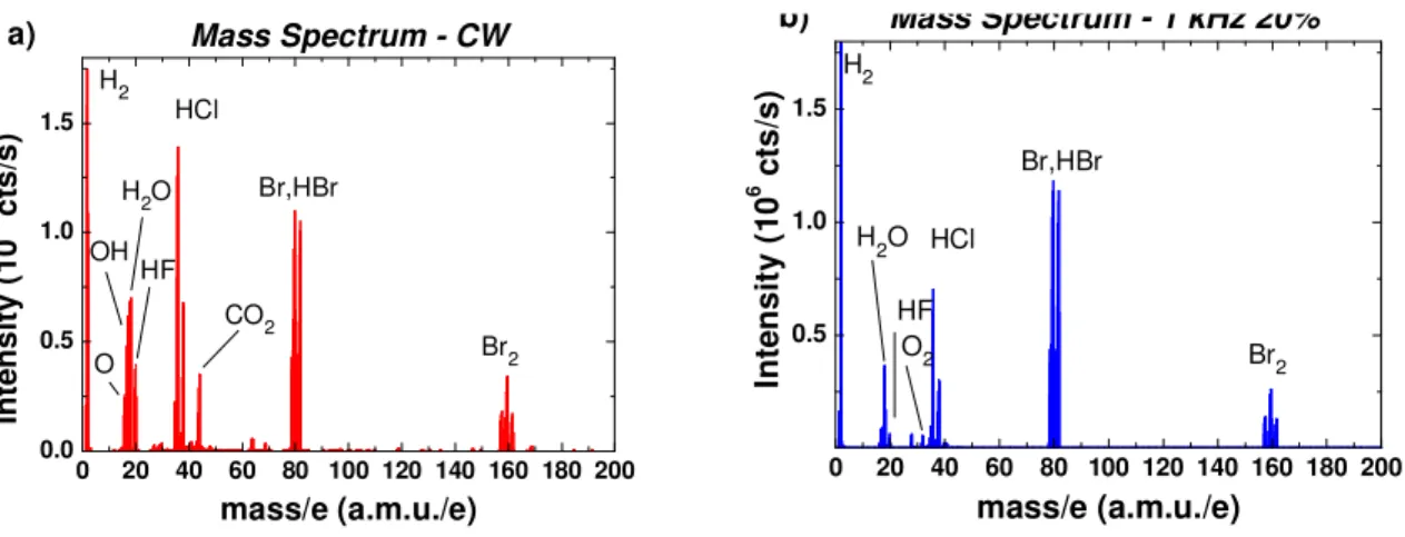
Fig. 2 shows the neutral mass spectra in the HBr/O2 plasma. We can see in that the plasma is composed of Br, HBr, Br2,
HxO and Ox with x between 1 and 2. CO2, HCl and HF come from the background that is not perfectly subtracted in
spectral mode (the chopper is not used). Note that the spectra correspond to the fractioned pattern of the plasma neutrals and that the mass spectrometer transmission function is not corrected here. As a consequence, no direct comparison of the species intensity can be done but we can compare the change of relative composition between the experiments.
0 20 40 60 80 100 120 140 160 180 200 0.0 0.5 1.0 1.5 Mass Spectrum - CW Br,HBr CO2 HCl HF O OH H2O In te n s ity (1 0 6 ct s/ s) mass/e (a.m.u./e) H2 Br2 a) 0 20 40 60 80 100 120 140 160 180 200 0.5 1.0 1.5 b) O2 In te n s it y ( 1 0 6 ct s /s ) mass/e (a.m.u./e) Br,HBr HCl HF H 2O H2 Br2 Mass Spectrum - 1 kHz 20%
Figure 2. Mass spectra of neutral species present in the HBr/O2 plasma at 0W bias power in a) continuous wave mode b)
pulsed at 1kHz 20% DC
To compare the plasma composition in CW and in pulsed mode, we quantified the density of Br, HBr, Br2 and O2 using
the beam chopper and threshold ionization. The other species (Hx, HxO, O) are not quantified due to a too small signal to
noise ratio. Figure 3 shows the variation of the O2, Br, Br2 and HBr densities as a function of the duty cycle in the
HBr/O2 plasma pulsed at 1kHz. Two important trends can be observed. First, it is clear that the total density of species
increases when the duty cycle decreases. We must keep in mind that Hx, O and HxO are not taken into account here.
The species density increase is attributed to a decrease of the time average gas temperature when the plasma is pulsed at lower duty cycle. Gas heating is basically reduced due to a lower average source power in pulsed mode. Assuming that H
and H2 have a similar density to Br and Br2, respectively, and neglecting O-containing species, we can estimate the
plasma temperature around 650 K in CW mode, consistent with the literature [11]. The temperature decreases and is expected to tend towards 330 K at very small duty cycle. Secondly, we can see that the relative amount of atomic species (reactive radicals) decreases when the duty cycle decreases. This indicates that the plasma gas molecules dissociation is reduced when the duty cycle decreases. As a consequence, the density of reactive radicals decreases when the plasma is pulsed at low duty cycle. Both phenomena are particularly significant at duty cycles below 35%.
0 20 40 60 80 100 0 100 200 300 S p e c ies De n s it y (1 0 12 cm -3 ) Duty Cycle (%) O2 Br Br2 HBr
Figure 3. Species density measured by molecular beam mass spectrometry in a HBr/O2 plasma pulsed at 1kHz. A duty cycle
of 0% corresponds to the gas (no plasma struck) while a duty cycle of 100% correspond to a CW plasma
We also investigated the average ion flux in pulsed HBr/O2 plasma. Figure 4. shows the composition of the ion flux
measured by mass spectrometry at the chamber walls for different duty cycles in the HBr/O2 plasma pulsed at 1kHz. The
light ions H+ and H2+ cannot be detected accurately with our system. As shown in this figure, the total ion flux decreases
when the duty cycle decreases. The ion flux is mostly composed of Br2+ and to a lower extend of H3O+. The other ions
represent less than 10% of the ion flux and consist of Br3+, HBr2+, H2Br+, HBr+ and Br+. The relative contribution of Br2+
increases when the duty cycle decreases. This is simply indicating that the balance between dissociation and recombination tends toward recombination when the duty cycle decreases.
0 20 40 60 80 100 0 2 4 6 8 10 12 14 Io n fl u x (a .u .) Duty Cycle (%) H3O+ Br3 + Br2H + Br2+ BrH2+ BrH+ Br+
Figure 4. Ion flux composition determined by mass spectrometry in HBr/O2 plasma pulsed at 1kHz. A duty cycle of 100%
corresponds to the CW mode.
The whole results in the HBr/O2 plasma indicate that pulsing the plasma leads to a decrease of the plasma temperature
and of the ion flux. The balance between dissociation and recombination tends towards more recombined and less dissociated species when the duty cycle decreases. This is impacting both the neutral flux and the ion flux composition.
1.7 Plasma diagnostic during silicon etching
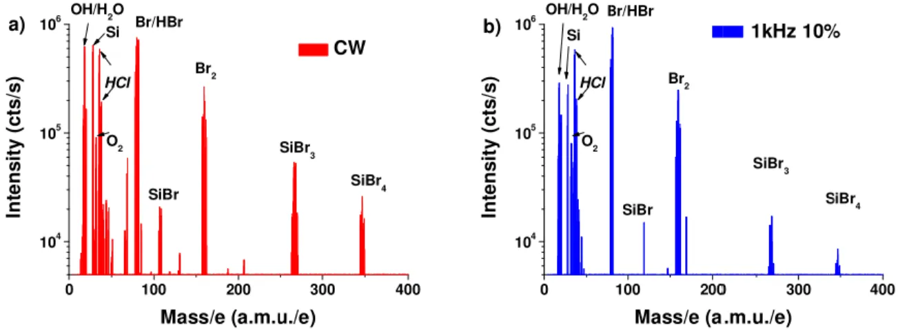
In a second set of experiments, the plasma composition is analyzed during silicon etching. As shown in figure 5, the plasma composition is strongly modified compared to the plasma without bias. Many silicon-containing species are now observed. When the plasma is pulsed at low duty cycle, we can see that the intensity of the Si-containing species
1005 909 809 709 609 509 YV/ 309 209 109 09
U
6 6 6 6 6 6 5t . SiE 10% Duty C )H 10 10 10 In te ns ity (c ts /s ) a) Figure 5. Similarly, the composed of species comp containing io observed for than the prop products and 0 1 2 3 4 5 6 7 8 9 10 a) Io n Fl ux ( a .u. ) Figure 6. to the CW The time-reso pulsed at 1 kH pulsation. Th the CW mode figure 7.b) th at 1kHz. For CW multiplie the probe is lo the ion flux i0 100 4 5 6 HCl O2 OH/H 2O Br/H SiB M Si Mass spectra o e ion flux com f silicon-conta pared to HBr ons. When the the neutral sp portion of hea the formation Non-Si-Si-conta Du 10%
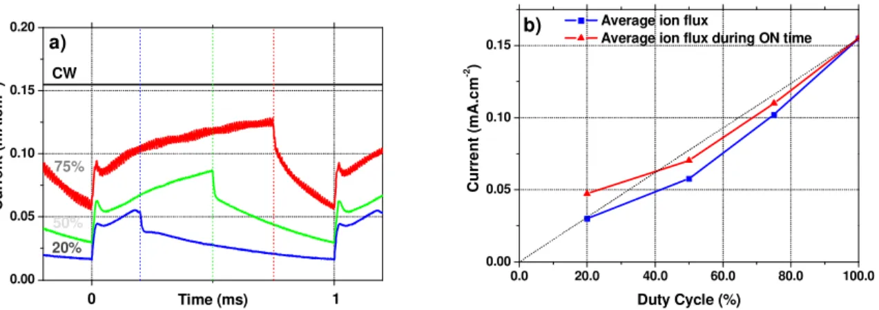
Ion flux compo W mode. a) Repa olved ion flux Hz. As shown he ion flux inc
e. During the he total averag
the duty cycl ed by the duty ower in pulsed in CW mode a 200 Br Br Br 2 Mass/e (a.m.u f neutrals durin mposition is str aining ions in molecules [1 e plasma is pu pecies. Furthe avier Si-conta n of more vola -containing io aining ion uty cycle (% osition during si artition between x has been in n in fig 7.a, th reases rapidly OFF time, th ge ion flux and
es investigate y cycle. This d plasma than and is the low
300 CW SiBr 3 u./e) SiBr4 ng silicon etchin rongly modifi n the CW plas 12]. This mea ulsed at low du ermore, the pr aining species atile etch by-p
100% n %) ilicon etching in n Si-containing nvestigated us here is a stron y at the beginn
e ion flux rap d the average ed here, the av means that fo n in CW mode west at the low
400 In te ns ity (c ts /s ) b) ng in HBr/O2 pl ied by silicon sma, which is ans that most duty cycle, the roportion of l
s (e.g. SiBr3+)
products when
n HBr/O2 plasm
g ions and non-S ing the plana ng modulation ning of the pu pidly drops bu ion flux from verage ion flux or identical pl e. The average west duty cycl
0 104 105 106 HCl O2 OH/H 2O B Si lasma a) in CW etching. As w s due to a low t of the ions e proportion o light Si-contai ), which indic n the plasma is ma pulsed at 1k Si containing io ar probe durin n of the ion f ulse, but does n ut does not rea m the ON time x is found to lasma ON tim e ion flux duri le. If we assu 100 200 Br/HBr SiBr Br2 Mass/e (a W mode b) pulse we can see in f wer ionization involved in s of silicon-cont ining element cates a lower s pulsed at low Hz. A duty cyc ons b) repartition ng silicon etch flux during th not reach the ach zero. We h e only for the
be always low me, the total am
ng the ON tim me a perfect p 0 300 SiBr 3 a.m.u./e) S 1kHz 10% ed at 1kHz 10% fig. 6, the ion n threshold en silicon etchin taining specie ts (e.g. Si+) d r fragmentatio w duty cycle. cle of 100% cor on of Si-contain hing in HBr/O he period of th value of the i have also rep
HBr/O2 plasm
wer than the io mount of ions me is always lo power couplin 400 SiBr4 % % flux is mostly nergy of these ng are silicon s decreases as ecreases more on of etch by rresponds ning ions O2 plasma he plasma on flux in orted (see ma pulsed on flux in s reaching ower than ng for the y e -s e
-bias power without collisional losses, we can approximate the ion energy by E=P/I with E the ion energy, P the -bias power, and I the ion flux [9]. For a constant bias power, the ion energy is thus strongly increased when the plasma is pulsed at low duty cycle.
0.00 0.05 0.10 0.15 0.20 1 0 20% CW 75% C u rr e n t (m A .c m -2 ) Time (ms) 50% a) 0.0 20.0 40.0 60.0 80.0 100.0 0.00 0.05 0.10 0.15
Average ion flux
Average ion flux during ON time
Cur re n t ( m A. c m -2 ) Duty Cycle (%) b)
Figure 7. Ion flux measured during silicon etchig in HBr/O2 plasma pulsed at 1kHz. A duty cycle of 100% corresponds to
the CW mode. a) time resolved measurement b) average ion flux and average ion flux during the plasma ON time only.
The analysis of the plasma during silicon etching shows that silicon etch by-products strongly contribute to the plasma composition and to the ion flux. When the plasma is pulsed, the presence of Si-containing species (both neutrals and ions) is reduced and Si-containing species are heavier confirming the reduced plasma dissociation under pulsed conditions. The ion flux is strongly reduced when the plasma is pulsed, which leads to an increased ion energy during the plasma ON time.
1.8 Application to silicon patterns etching
The HBr/O2 plasma investigated above has been used to pattern trenches in silicon using a SiO2 hard mask. For these
experiments, we used time compensation, meaning that the etching time is set to have identical plasma ON time for all experiments. The time compensated etch rate is defined as the etch rate divided by the duty cycle, i.e. the etch rate considering only the plasma ON time. Figure 8 shows semi-isolated silicon patterns with equal line and space widths of 80 nm. When the duty cycle is reduced, we can observe several phenomena: 1) The etched depth increases. 2) The hard mask is less damaged. 3) The difference between open areas and dense patterns is reduced. 4) The shape of the micro trenching evolves.
The higher etched depth at low duty cycle reflects an increase in the time-compensated etch rate. This phenomenon is explained by an increased availability of etching radicals during the process. Indeed, since the density of neutrals species (and particularly reactive radicals) is hardly modulated in pulsed plasma at 1 kHz [3], a significant flux of reactive radicals impinges the surface during the OFF time and may participate to silicon etching. Even if the total reactive radicals density in the plasma decreases when the duty cycle decreases, the flux of reactive radicals during the OFF time compensates for this decrease, leading to an increased time compensated etch rate.
By contrast, the SiO2 etch rate is driven by the ion flux and the square root of the energy. Even if the maximum ion
energy increases at low duty cycle, the flux of energetic ions strongly decreases, which leads to a decrease of the SiO2
etch rate. This explains why the SiO2 hard mask is better preserved when the plasma is pulsed at low duty cycle.
The difference between dense and open areas is explained by a variation of the passivation layers thicknesses. Indeed, the passivation layers are formed by the deposition of etch by-products and their subsequent oxidation at the pattern
lower density differential ch Finally, the sh observe broad inhibitors clo containing sp collection ang cycle is 20% micro trenchi locally enhan Figure 8. mask. The In this paper, pulsed, the ne ions’ chemic species, and t proportion of species, the io time is reduc strongly chan reduced hard cycle which i This work w Research Ag frame of the C [1] Bann adva [2] Hwa 37, 2 [3] Bod plasm 1133 [4] Sam selec 12(6 y of reactive r harges when t hape of the m d trenches as u ose to the edge pecies and dis gle (far from or below, we ing is explain ncing the etchi
Semi isolated s e etching time i
, we have inve eutrals density cal nature bec the ion flux is f silicon conta
on flux is larg ced compared nges the profil d mask consum improves the l was supported ency (ANR) CT208 Reach na, S., Agarw anced dry etch ang, G. S., Gia 2291 – 2301 ( art, P., Brihou mas: Impact 302 (2011) mukawa, S., T ctive, highly 6), 3300 (1994 radicals in the the plasma is p microtrenching usually observ es of the patte ssociated etch patterns edge can see that l ned by the sha ing [13] and b silicon patterns is set to have id estigated the p y is increased comes more s mostly comp aining species gely modulate d to CW plasm le of the etche mption at low local uniformi d by the Fren under the con hing 22 project
wal, A., Cung hing processes apis, K. P., “M (1998). um, M., Cung of the pulsin Terada, K., “P anisotropic, a 4). plasma and t pulsed. evolves when ved using HB erns due to a s h by-products) es). This redu local micro tre ape of the pat by a transition
etched in an HB dentical plasma
C
pulsing of an d and the plasm
molecular. D posed of silico s both as neut ed when the p ma, leading to ed silicon pat w duty cycle.
ity and the pat
ACKN
ch Governme ntract number t, and by the F
R
ge, A., Darno s,” Journal of Mechanism of ge, G., Jouber ng parameters Pulse-time mo and less-char the reduced at n the duty cyc
Br/O2 plasmas
shading effect ) are availabl uces the broad enching forms ttern sidewalls towards more Br/O2 plasma p ON time for al
CONCLUS
HBr/O2 plasm ma is less dis During the et on-containing trals in the pl plasma is pulse o an increase tterns, with an The passivat tterns profile cNOWLEDG
ent program “ r ANR10-EQ French RenateREFEREN
on, M., Pargo f Vacuum Scie f charging red rt, O., Sadegh s on the radi odulated elec rging polycry ttack of the pa cle is reduced. [13]. They or . At low duty e to slow dow d micro trench s at the edges s that focuses e ion limited e pulsed 1 kHz an l experiments (SION
ma for silicon sociated. Furt tching, the pl ions. Pulsing lasma and as ed at 1kHz. T of the instan n enhanced timion layers are control.
GMENTS
“Investisemen QPX-33, by th ech network.NCES
on, E., Jouber
nce Technolog duction in puls hi, N., “Analy cal densities, ctron cyclotro stalline silico assivation laye In CW mode riginate from t cycle, much l wn the etchin hing at lower between patte the ions at th etching regime nd at various dut so-called time c etching appli thermore, the lasma contain the plasma at ions in the io The instantane ntaneous ion e me-compensat e thinner and
S
nts d’Avenir” he European C rt, O., “Pulsed gy A, 30(4), 0 sed plasma et ysis of pulsed ” Journal of on resonance on patterning,” ers by ions de e and at large dthe lower dep less etch inhib ng in the regio duty cycle. W erns and the e he microtrenc e at low duty
uty cycle with a compensation)
ication. When ion flux is re ns many silic t low duty cyc on flux. Contr eous ion flux d energy. Pulsin ted etching of more uniform ” managed by CATRENE p d high-density 040801 (2012) tching,” Jpn. J d high-density f Applied Phy plasma etchi ” J. Vac. Sci eflected by the duty cycle, we osition of etch bitors (oxygen ons with large When the duty tch front. This ching location
cycle.
SiO2 hard
n the plasma is educed and the con-containing cle reduces the rary to neutra during the ON ng the plasma f silicon and a m at low duty y the Nationa rogram in the y plasmas fo ). J. Appl. Phys. y HBr and Cl ysics, 110(11)
ing for highly
i. Technol. B e e h n e y s n, s e g e al N a a y al e r , 2 ), y B, even at 10% of duty cycle, while some lateral etching was observed in the CW mode. This may be explained by the
[5] Petit-Etienne, C., Darnon, M., Vallier, M., Pargon, E., Cunge, G., Boulard, F., Banna, S., Lill, T., Joubert, O., “Reducing damage to si substrates during gate etching processes by synchronous plasma pulsing,” J. Vac. Sci.
Technol. B, 28(5), 926 – 934 (2010)
[6] Cunge, G., Bodart, P., Brihoum, M., Boulard, F., Chevolleau, T., Sadeghi, N., “Measurement of free radical kinetics in pulsed plasmas by uv and vuv absorption spectroscopy and by modulated beam mass spectrometry,”
Plasma Sources Science and Technology, 21, 024006 (2012)
[7] Haass, M., Darnon, M., Cunge, G., Joubert, O., Banna, S., “Silicon etching in a pulsed HBr/O2 plasma: I.
plasma analysis by mass spectrometry”, to be submitted to J. Vac. Sci. Technol. B
[8] Braithwaite, N. S. J., Booth, J. P., Cunge, G., “A novel electrostatic probe method for ion flux measurements,”
Plasma Sources Sci. Technol., 5, 677–684 (1996)
[9] Brihoum, M., Cunge, G., Darnon, M., Braithwaite, S. S. J., Gahan, D., Joubert, O., “Ion flux and ion energy distribution function measurements in synchronously pulsed ICP plasmas,” J. Vac. Sci. Technol. A, in proof, (2013)
[10] Haass, M., Darnon, M., Joubert, O., “Sidewall passivation layer thickness and composition profiles of etched silicon patterns from angle resolved x-ray photoelectron spectroscopy analysis,” Journal of Applied Physics, 111(12), 124905 (2012)
[11] Cunge, G., Ramos, R., Vempaire, D., Touzeau, M., Neijbauer, M., Sadeghi, N., “Gas temperature measurement
in CF4, SF6, O2, Cl2, and HBr inductively coupled plasmas,” Journal of Vacuum Science & Technology A,
27(3), 471–478 (2009).
[12] Cunge, G., Inglebert, R. L., Joubert, O., Vallier, O., Sadeghi, N., “Ion flux composition in HBr/Cl2/O2 and
HBr/Cl2/O2/CF4 chemistries during silicon etching in industrial high-density plasmas,” J. Vac. Sci. Technol. B
20 (5), 2137 (2002).
[13] Vyvoda, M. A., Li, M., Graves, D. B., Lee, H., Malyshev, M. V., . Klemens, F. P., Lee, J. T. C., Donnelly, V.
M., “Role of sidewall scattering in feature profile evolution during Cl2 and HBr plasma etching of silicon,”