Digital Cellular Solids: reconfigurable composite materials
by
Kenneth C. Cheung
B.Arch., Cornell University, 2005
S.M., Massachusetts Institute of Technology, 2007
Submitted to the Program in Media Arts and Sciences, School of Architecture and Planning
in partial fulfillment of the requirements for the degree of
Doctor of Philosophy
at the
MASSACHUSETTS INSTITUTE OF TECHNOLOGY
September 2012
!AAH UETTS: INSTITUTE
'I20 -Jt
RA
ES
@ 2012 Massachusetts Institute of Technology. all rights reserved
Signature of Author:
~-Q)
Program in Media Arts and Sciences
August 7, 2012
z-~2
Certified by:
Prof. Neil Gershenfeld
Director, Center for Bits and Atoms (CBA)
Program in Media Arts and Sciences
Accepted by:
Prof. Patricia Maes
Associate Academic Head
Program in Media Arts and Sciences
Kenneth C. Cheung, PhD Thesis, Media Arts & Sciences, MIT
V
4
(This page intentionally left blank)
Kenneth C. Cheung, PhD Thesis, Media Arts & Sciences, MIT Page 2
Digital Cellular Solids: reconfigurable composite materials
byKenneth C. Cheung
Submitted to the Program in Media Arts and Sciences, School of Architecture and Planning on August 7, 2012 in partial fulfillment of the
requirements for the degree of Doctor of Philosophy
Abstract
Digital materials are comprised of a small number of types of discrete physical building blocks, which assemble to form constructions that meet the versatility and scalability of digital computation and communication systems. This work seeks to demonstrate the applicability of a digital material approach in designing new cellular materials and methods for assembly of structures with static reconfigurability. The science of cellular solids has enabled the widespread use of lightweight materials to meet important engineering needs, such as passive energy absorption, but they are not in widespread use for structural applications, perhaps due to a large gap between the strength and stiffness to weight ratios of popular classical solids, and the
performance of known lightweight cellular materials that are produced from the same constituent material. The engineering of fiber reinforced composite materials has enabled structures with large reductions in weight for given strength and stiffness targets, but at very high design and processing costs, and many challenges producing mechanical interfaces (joints). Digital materials promise scalable methods of producing functional things with reconfigurable sets of discrete and compatible parts, but the presence of many reversible connections raises questions about the performance of the end result. Digital Cellular Solids are cellular solids that exhibit improvements in relative stiffness and strength compared to relative density, over current practices for producing
lightweight materials. This is accomplished by assembling lattice geometries that perform better than any that we know how to make with traditional methods. When implemented with fiber
composites, the result is not only stiffer and stronger than any previously known ultra-light material, but it presents a new scalable and flexible workflow for applying fiber composites to engineering problems.
Thesis Supervisor: Prof. Neil Gershenfeld
Director, Center for Bits and Atoms (CBA) Program in Media Arts and Sciences
(This page intentionally left blank)
Kenneth C. Cheung, PhD Thesis, Media Arts & Sciences, MIT Page 4
Digital Cellular Solids: reconfigurable composite materials
byKenneth C. Cheung
Thesis Reader:
Erik Demaine, Ph.D. Professor of Electrical Engineering and Computer Science (EECS)
Computer Science and Artificial Intelligence Lab
(This page intentionally left blank)
Kenneth C. Cheung, PhD Thesis, Media Arts & Sciences, MIT Page 6
Digital Cellular Solids: reconfigurable composite materials
byKenneth C. Cheung
Thesis Reader:
Shuguang Zhang, Ph.D. Center for Bits and Atoms (CBA)
Kenneth C. Cheung, PhD Thesis, Media Arts & Sciences, MIT " /x
' Z
(This page intentionally left blank)
Kenneth C. Cheung, PhD Thesis, Media Arts & Sciences, MIT Page 8
Acknowledgements
I thank Neil Gershenfeld and the Center for Bits and Atoms for the vision and environment to
support this work. The diversity of perspective amongst the faculty and students of CBA makes for a wonderful place to do research.
The fab labs have allowed me to develop a perspective of technology and society that will always frame my work. Thank you, to Sherry Lassiter, for your tireless work in support of the entire fab lab network.
Sometimes, I'm asked: what makes MIT work? I answer -it's the community of interested people who always seem to be able to dispense with the old and discover new and more beautiful ways of seeing the world. Of these, I must in particular thank Erik Demaine and Shuguang Zhang for being my committee members, and for being good friends and offering sage advice.
The work presented here, is about making things, and how we might be able to make things in better ways. In order to try and show this, I spent a lot of time making things. This often meant using facilities and equipment in ways that are not described in the manuals. Thank you, John D, for making these accessible while keeping us safe. I must also thank the many helping hands that I had during the course of this project, including Joseph K, Stevie B, Matt K, and Sarah H.
To the individuals who helped to fuel the discussions that resulted in this work, I thank you. Chris W; working with you and everyone at the Spirit Aerosystems Composite Development Center has been a pleasure. Mitch Z and Gill P, the groups of researchers that you pull together are inspiring. To Michael K, thank you for your care.
To my family, and in particular my mother and father, Christine and Moses, thank you for all of the opportunity that one could hope for.
To Laura, thank you for appreciating me for who I am.
(This page intentionally left blank)
Kenneth C. Cheung, PhD Thesis, Media Arts & Sciences, MIT Page 10
Table of Contents Introduction...17 Digital M aterials ... 17 Background...19 Natural Fabrication ... 19 Natural M aterials...20 Engineered Fabrication... 21 Engineered M aterials ... 23
Design and Analysis ... 25
Geom etry...28
M echanics...40
Case Study Digital M aterial Design - The Cuboct Truss... 47
M ethod ... 52
W orkflow ... 52
Part Fabrication M ethod ... 54
Physical Testing M ethod ... 61
Results ... 69
Density ... 69
M echanical Perform ance ... 69
Failure M odes ... 79
Applications ... 83
Reconfigurability ... 83
Interfaces ... 92
Skins (tw o-dim ensional digital cellular m aterials) ... 93
Self Assem bly...97
Conclusions ... 99
Grand Challenges...107
#1 - Engineered M olecular Digital Com posites ... 107
#2 Digital Com posite Electronics Reconfigurator ... 108
#3 - Digital Flexural M echanism s ... 109
#4 Passive Shape Optimization and Resonant Aerodynamic Propulsion...110
#5 Rapidly Deployable Infrastructure... 111
#6 Three Dim ensional Villages ... 112
References...115
Appendices...120
Kenneth C. Cheung, PhD Thesis, Media Arts & Sciences, MIT Page 12
Table of Figures
FIGURE 1 EXAMPLE DIGITAL MATERIALS 18
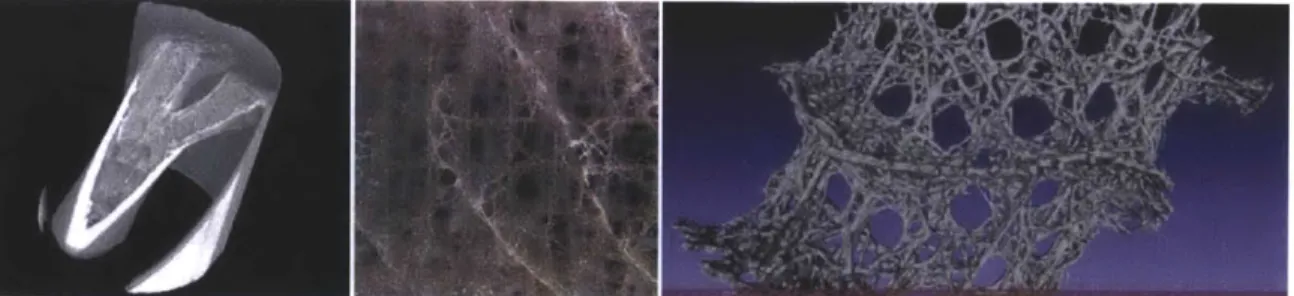
FIGURE 2 CT SCAN OF WILD PHEASANT BONE, PICTURE OF EUPLECTELLA SP. AND CT SCAN 20
FIGURE 3 THE BOEING DREAMLIFTER: AN EXAMPLE OF THE LENGTHS (AND WIDTHS) THAT ARE GONE TO, IN TODAY'S LEADING EDGE COMPOSITE PRODUCTION. THIS AIRCRAFT WAS DESIGNED AND MANUFACTURED SPECIFICALLY AS PART OF THE PRODUCTION PROCESS FOR THE BOEING 787 PASSENGER AIRCRAFT, WHICH IS COMPRISED OF LARGE MONOLITHIC
COMPOSITE COMPONENTS. 22
FIGURE 4 AIRCRAFT OF CONVENTIONAL RECONFIGURABLE MATTER 23 FIGURE 5 CONCEPT DIAGRAM FOR DIGITAL COMPOSITES - CHAINED CONTINUOUS FIBER LOOPS 25
FIGURE 6 PART SIZE HIERARCHY, CORE STRUCTURAL VARIATION, INTRODUCTION OF VOIDS AS METHODS OF STRUCTURAL TUNING
26
FIGURE 7 SNAP FIT FLEXURAL LATTICE STUDIES: LEFT, MIDDLE, TENSEGRITY CRYSTAL; RIGHT, HYPERBOLIC/GEODESIC SURFACE
KIT 27
FIGURE 8 SNAP FIT FLEXURAL LATTICE STUDIES: LEFT, SIMPLE CUBIC LATTICE WITH TWO PART SCHEME; RIGHT, 12 CONNECTED
OCTET TRUSS WITH THREE PART SCHEME 28
FIGURE 9 TWO PART SCHEME FOR CUBOCT TRUSS 29
FIGURE 10 RELATIVE DENSITY VS MODULUS SCALING CURVES 44
FIGURE 11 HYPOTHETICAL DESIGNED DIGITAL MATERIAL STRESS STRAIN CURVES 45
FIGURE 12 CUBOCT TRUSS GEOMETRY 48
FIGURE 13 CASE STUDY DESIGN ASSEMBLY 49
FIGURE 14 CASE STUDY DESIGN LOAD RESPONSE DIAGRAM 50 FIGURE 15 CASE STUDY DESIGN FIBER ORIENTATION LAYOUT 50
FIGURE 16 CASE STUDY DESIGN ASSEMBLIES 51
FIGURE 17 DESIGN WORKFLOW 52
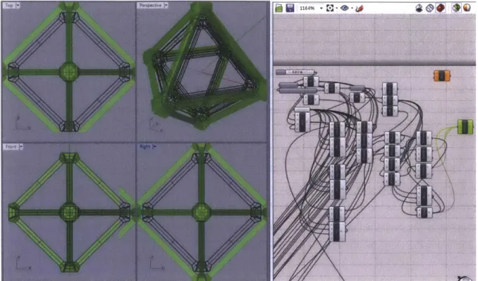
FIGURE 18 PARAMETRIC DESIGN TOOLS EMPLOYED FOR DIGITAL COMPOSITES EXPERIMENTS; RHINOCEROS API AND
GRASSHOPPER 53
FIGURE 19 OPTIMIZED PART MULTIPLEXED WINDING MOLD DESIGN 54 FIGURE 20 OPTIMIZED PART MULTIPLEXED WINDING MOLD ASSEMBLY 55 FIGURE 21 OPTIMIZED PART MULTIPLEXED WINDING PROCESS 55 FIGURE 22 OPTIMIZED PART MULTIPLEXED WINDING SLICING 56
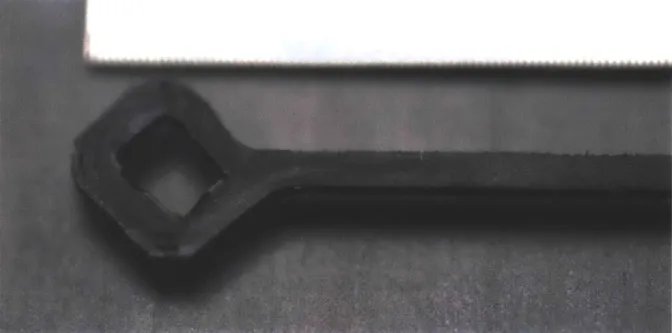
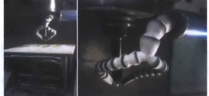
FIGURE 23 CLOSE-UP VIEW OF PART PRODUCED BY MULTIPLEXED WINDING. GRADATIONS ON SCALE ARE 100THS OF AN INCH. 57 FIGURE 24 COMPARISON CNC MILLING OF QUASI-ISOTROPIC LAMINATE PROCESS - VORTEX TUBE COOLING, DIAMOND COATED
TOOLING 58
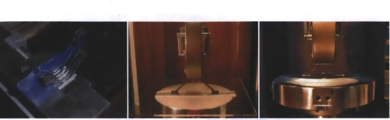
FIGURE 25 PHOTOGRAPHS OF DIGITAL COMPOSITE TEST SPECIMEN 59
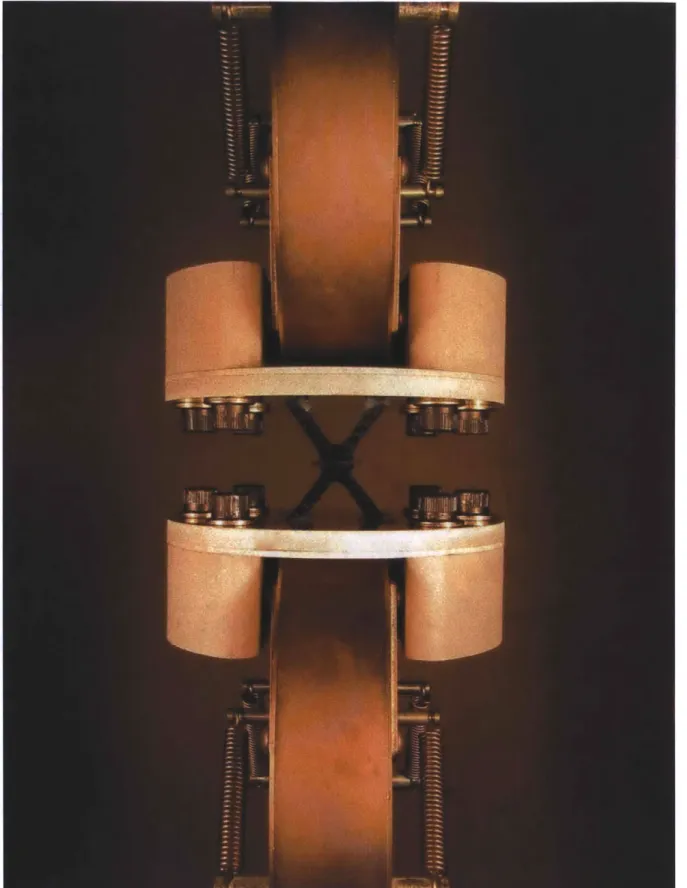
FIGURE 26 PRELIMINARY CONNECTION TESTING (INSTRON 4411) 60
FIGURE 27 PHYSICAL TESTING OF AN EARLY DIGITAL COMPOSITE SAMPLE 61 FIGURE 28 INITIAL PART CONSTRAINT TESTING; SETUP, LOAD TESTING WITH SLIDING CONSTRAINT, LOAD TESTING WITH
FIXED CONSTRAINT 62
FIGURE 29 INITIAL RESULTS CONSTRAINT TESTING, PROVIDING UPPER BOUND 63
FIGURE 30 CONNECTION TESTING 63
FIGURE 31 DIMENSIONAL TOLERANCE EVALUATION, ISOTROPY MEASUREMENT SAMPLES 64
FIGURE 32 2X2X2, OPTIMIZED PARTS 64
FIGURE 33 FIXTURING AND FINAL TESTING 65
FIGURE 34 FIXTURE COMPLIANCE TESTING WITH SOLID ALUMINUM BLOCK 66
FIGURE 35 RAw DATA, WITHOUT COMPLIANCE CORRECTION 67
FIGURE 36 COMPLIANCE CORRECTED DATA 67
FIGURE 37 OPTIMIZED PARTS AND CONVENTIONAL PARTS, 69
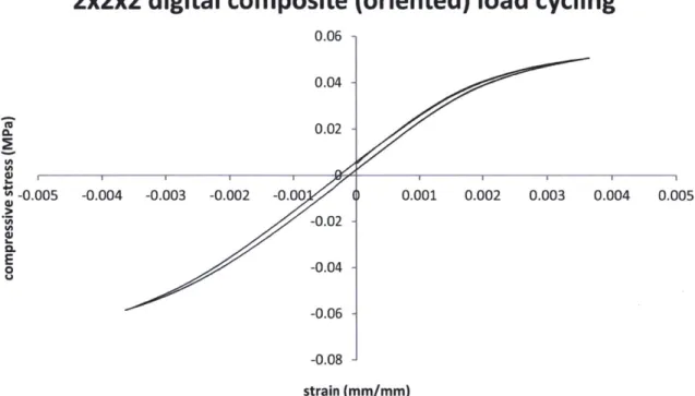
FIGURE 38 TENSION AND COMPRESSION CYCLING SHOWING TRANSITION FROM LINEAR TO NON-LINEAR ELASTICITY WITH LOW
HYSTERESIS 70
FIGURE 39 STRESS STRAIN CHART FOR THE SAMPLES SHOWN IN THE PHOTOGRAPHS BELOW. 71
FIGURE 40 SINGLE UNIT (UNCONSTRAINED ON EDGES) RESPONSE TO TENSION (LEFT) AND COMPRESSION (RIGHT) SHOWING
COORDINATED BUCKLING. 71
FIGURE 41 ANSYS SIMULATION WITH DEFLECTION MULTIPLIER SHOWING COORDINATED BUCKLING MODE 72 FIGURE 42 MODULUS PLOTTED AGAINST NORMALIZED SIZE (# CELLS), ANSYS SIMULATION 72 FIGURE 43 RELATIVE STRENGTH AND MODULUS OF DIGITAL COMPOSITES 73
FIGURE 44 DIGITAL COMPOSITE MODULUS SCALING WITH DENSITY 74
FIGURE 45 PREVIOUSLY KNOWN ULTRA-LIGHT MATERIALS 77
FIGURE 46 PREVIOUSLY KNOWN CELLULAR MATERIALS WITH BETTER THAN QUADRATIC DENSITY MODULUS SCALING PROPERTIES
78
FIGURE 47 DIGITAL CELLULAR COMPOSITE MATERIAL PERFORMANCE -THE LINE REPRESENTS QUADRATIC SCALING FROM THE
IDEAL AXIALLY ALIGNED CARBON FIBER COMPOSITE SOLID. 79
FIGURE 48 SEQUENTIAL CYCLIC LOADING AFTER FAILURE EVENTS, SHOWING GRADUAL REDUCTION IN EFFECTIVE MODULUS _ 80 FIGURE 49 DESIGNER FAILURE MODES: CRACK PROPAGATION, NON-LINEAR ELASTICITY BY ELASTIC BUCKLING, BRITTLE
CRUSHING 81
FIGURE 50 IMPERIAL PROBE DROID 83
FIGURE 51 TUNABLE ELASTICITY 84
FIGURE 52 TEST FLEXURE TOWER SETUP 85
FIGURE 53 DIGITAL COMPOSITE COLUMN PROFILE, LOADING SCHEME, (PHOTOGRAPHS) 86
FIGURE 54 DIGITAL COMPOSITE COLUMN PROFILE, SIMULATION AND ACTUAL EXPERIMENT (PHOTOGRAPH) FOR FIRST ASSEMBLY,
SHOWING PURE AXIAL COMPRESSION 87
FIGURE 55 SIMULATION AND ACTUAL EXPERIMENT (PHOTOGRAPHS) FOR SIMPLE SINGLE AXIS BUCKLING ASSEMBLY 88
FIGURE 56 SIMULATION AND ACTUAL EXPERIMENT (PHOTOGRAPHS) FOR COMPLEX BUCKLING ASSEMBLY 89 FIGURE 57 WING SHAPE MORPHING SCHEMES (HIGH LIFT, CRUISE, CONTROL/FLAP); AIRFOIL SHAPES FOR DIFFERENT
AERODYNAMIC REGIMES 90
FIGURE 58 DIGITAL AIRFOIL SHAPE MORPHING SCHEME, PARTS 91
FIGURE 59 DIGITAL CELLULAR AIRFOIL 92
FIGURE 60 DIGITAL CELLULAR AIRFOIL: INTERFACE BETWEEN STRUCTURE AND AIRSTREAM PROVIDED BY CELLULAR SKIN _ 93
FIGURE 61 DIGITAL CELLULAR AIRFOIL 94
FIGURE 62 DIGITAL CELLULAR AIRFOIL IN THE MIT WRIGHT BROTHERS WIND TUNNEL 95
FIGURE 63 1D 4 3D WORKFLOW WITH POTENTIAL APPLICATIONS TO DIGITAL COMPOSITE ASSEMBLY (CHEUNG, ET AL 2011) 97
FIGURE 64 ONE DIMENSIONAL WORKFLOW FOR FRAMEWORK CONSTRUCTION 98
FIGURE 65 DIGITAL COMPOSITE WING WEDGE, SIZED TO REPLACE EXISTING COMPONENT ON COMMERCIAL JET PRODUCED BY
SPIRITAERO 102
FIGURE 66 BEAM PERFORMANCE INDEX FOR VARIOUS MATERIALS 104
FIGURE 67 ANDEAN CONDOR 105
FIGURE 68 ENGINEERED MOLECULAR DIGITAL COMPOSITES 107 FIGURE 69 CONDUCTIVE AND INSULATING DIGITAL COMPOSITE PARTS 108 FIGURE 70 DIGITAL COMPOSITE ORTHOSES AND PROSTHESES 109
FIGURE 71 DIGITAL COMPOSITE SHAPE MORPHING WINGS 110
Kenneth C. Cheung, PhD Thesis, Media Arts & Sciences, MIT Page 14
FIGURE 72RESONANT AERODYNAMIC PROPULSION 110 FIGURE 73 DISASTER RELIEF WITH RAPIDLY DEPLOYABLE DIGITAL COMPOSITE INFRASTRUCTURE 111
FIGURE 74 AERIAL CONCEPT VIEW 112
FIGURE 75 MIT CAMPUS, CONSOLIDATED. 113
FIGURE 76 THREE DIMENSIONAL VILLAGE FLOOR PLAN (ABOVE), SECTION (BELOW) 114
FIGURE 77 PRELIMINARY CHAIN TESTING 121
FIGURE 78 PROCESS DEVELOPMENT TESTING 123
FIGURE 79 3D PRINTED (X10 SCALE) CT SCAN DATA FROM BONES 129
FIGURE 80 CUSTOM CT DATA PROCESSING SOFTWARE 130
FIGURE 81 CT DATA RENDERINGS 131
FIGURE 82 CURVATURE BASED CREASE FINDING ON STANFORD BUNNY MODEL 131 FIGURE 83 PRELIMINARY MATERIAL DISTRIBUTION CHARACTERIZATION METHOD 132
FIGURE 84 STRUCTURAL WEDGE COMPARISON MODEL 133
FIGURE 85 GENERIC WING Box RELATIVE PRESSURE MAP 134
FIGURE 86 MULTIPLEXED WINDING MOLD DIAGRAM 135
FIGURE 87 ASSEMBLY PROCESS 138
FIGURE 88 FIBER LAYUP WITHIN COMPONENTS 139
FIGURE 89 SLICED PULTRUSION / BONDED PARTS 140
FIGURE 90 FIBER LAYUP WITHIN PRE-FORMED LAMINATE 140
FIGURE 91 - GENERALIZED INTERACTION POTENTIAL DIAGRAMS 143 FIGURE 92 A SCHEME WITH ONLY ONE PART TYPE (PINS INCORPORATED) 144 FIGURE 93 ROLL TO ROLL MANUFACTURING OF POP-UP CELLS 145
FIGURE 94 KELVIN STRUCTURE 145
FIGURE 95 TODAY'S ASSEMBLERS 145
FIGURE 96 DIRECTIONAL CONNECTION STRUCTURES (RIGHT) 146
FIGURE 97 DIRECTIONAL CONNECTION SCHEMATIC 147
FIGURE 98 DIRECTIONAL CONNECTION CELL TYPES (TENSION, LEFT; COMPRESSION, RIGHT) 147
(This page intentionally left blank)
Kenneth C. Cheung, PhD Thesis, Media Arts & Sciences, MIT Page 16
Introduction
Digital Materials
The digital revolutions in communication and computation have enabled engineered systems that functionally scale to Avogadro numbers of their functional units. This is largely achieved through error reduction and correction strategies that rely on stochastic near-certainties that are driven by the physics of the system. Biology shows us that these goals can be satisfied in a system for fabricating things, or "programming matter," through the encoding of structural and functional information, with a small and discrete set of parts. We refer to materials that follow these principles as digital materials, and the methods of organizing these materials into functional
assemblies as digital fabrication.
To realize designed and engineered digital materials and fabrication processes, I look to develop low cost and reversible material systems that can form mechanically useful assemblies and require low precision assembly methods. While determining exactly how biological fabrication works is an unsolved problem, the complex structural requirements that are satisfied in natural
systems provide proof of their possibility. Much progress is being made on determining the exact schemas of construction (i.e. protein folding, growth regulation) in biological systems, as well. In any case, the potential complexity and diversity of assemblies that are accessible by this digital fabrication approach has long been appreciated (e.g. Mayer 2005).
Conventional designed and engineered fabrication methods employ digital computation and communication algorithms to control analog mechanical equipment that additively or subtractively forms shapes from masses of bulk material. Digital material systems propose a method for
fabrication from discrete parts with discrete relative local positioning, instead of continuous variation of composition and location of material, as in an analog fabrication system. This may be thought of as printing, noting that an important distinction between digital material printing and conventional commercially available three dimensional printing processes is that digital material printing is reversible, and the information regarding the shape, assembly, and function of a finished product is intrinsic to the material that it is composed of ("...can you tell the shape and fabrication method of a part by its function?...").
The process of printing ink on pages changed fundamentally with the introduction of the page description language, which enabled the "desktop publishing" revolution of the 1980s by
packaging the information describing printed material as executable programs. Similarly, a "desktop fabrication" revolution will rely on the transfer of information to fabrication systems, as part specific executable programs, instead of machine specific control instructions (Gershenfeld
2005). This is enabled by embedding metrology and positioning constraints within the design of
material building blocks.
Figure 1 Example Digital Materials
There are various ways to envision architectures for such a programmable matter system. The biological analogy leads us towards self-assembling and self-reconfigurable systems with both
extrinsically functional products and intrinsically functional machinery (for operating on the system itself) being made of the same fundamental set of units. A considerably simpler model allows for an external operator ("hand-of-[your preferred deity]," if you will) to perform assembly and reconfiguration steps on mechanically passive parts. It is this latter model that we propose for the subject of this work.
A primary proposition of this work is that properly engineered kits-of-parts (with many
fewer primitives than your average reconfigurable toy construction set) with automated assembly and disassembly (hence static reconfigurability) can produce functionally useful parts (not just toys, although this is also acceptable use!) that have life cycle efficiencies exceeding that of conventional engineered fabrication methods. The included case study addresses the mechanical digital material design problem, from the perspective of analysis and testing of an example called digital composites.
Kenneth C. Cheung, PhD Thesis, Media Arts & Sciences, MIT Page 18
Background
Natural Fabrication
Imagine a structural building kit for building high performance structures ranging from centimeters to tens of meters. In this kit, there is a small and finite set of types of building blocks.
Some of these types are very strong, and others are very tough. For structural purposes, it is typical to assemble these units in different ways -for example, very dense or very sparse. Different
structural types can also be combined to strategically manage a wide variety of loading conditions. From the point of view of composition, the dense assemblies resemble structures formed from bricks, as they are composed of regular units at regular spacing, and the sparse assemblies
resemble flexible space frames, with regular units that are compliant enough to permit a wider (yet still finite) set of valid connections.
Structures that are built with this kit may be well tuned to support a wide range of static and dynamic loads. Further, the system has the ability to gradually adapt to new load patterns, with mobile units that travel over the structure and delete portions of its own structure, as well as other units that are capable of adding new material. Even in its densest form, these structures maintain an integral set of communication channels that allow for the diffusion of information, such as signaling the need to adapt the structure.
The smallest birds and the largest whales share a system that fits this description, in their bones. Building block types include cortical plexiform bone, with its dense brick-like assemblies. Cells that resorb or delete existing bone are known as osteoclasts, and osteoblasts add new structural material. These cells are set into coordinated action with the help of communication channels known as inter-lacunar canaliculi. The efficiency with which this system maintains itself and adapts to new loading patterns - or even failures - far outperforms conventional engineered structural systems, and provides real inspiration for our research on Digital Materials, which seeks to design and engineer artificial systems with some of the qualities described above.
Figure 2 CT scan of wild pheasant bone, picture of Euplectella sp. and CT scan
Natural Materials
Material science has made much progress in the description of natural cellular solids, such as wood and bone (Gibson 2005). We may consider such biological cellular solids to be a prime example of natural structural fabrication that is high performing with complex constraints. For analysis, it is now typical to treat cellular materials as classical solids. The properties of the cellular solid are therefore defined by the properties of the solid material that it is made from (the
"constituent solid"), and its spatial configuration (Gibson & Ashby 1988).
Much of the art -of continuum mechanics of cellular solids -lies in developing a classically analyzed cell model that is an effective representation of the stochastically varying nature of the actual material. The field has done quite well to characterize readily available natural cellular solids in this manner. Natural scaling laws are well known (Gibson & Ashby 1988), and relate the
mechanical properties of the cellular solid to those of the constituent solid material (that which comprises cell edges and/or walls), via the relative density of the former to the latter.
A large variety of applications have developed around the science of cellular solids,
evidenced by the widespread use of these materials for passive energy absorption, thermal
insulation, and fluid filtering (Maiti et al 1984). However, despite their low density, they are largely limited in their use for structural applications, because for the weight of popular and inexpensive cellular solids, they are not particularly strong. The conventional model typically considers the geometry of stochastic foams to be such that transverse beam bending dominates the behavior of the material (Gibson & Ashby 1988). This results in an overall relative modulus that is expected to be proportional to the square of the relative density, for natural foams.
Kenneth C. Cheung, PhD Thesis, Media Arts & Sciences, MIT Page 20
E* p2
-C c- Equation 1
Es Ps2
In additional to biological cellular solids, this scaling law is useful for analyzing and
predicting the properties of non-biological natural foams (e.g. pumice) and engineered foams (e.g. polymer foams, metal foams), whether chemically or mechanically produced. Further analogies to natural cellular structures exist in conventional engineered structures (Aizenberg et al 2005). Depending on the relative scale desired for analysis, one might look towards the aforementioned engineered foams, or space frame trusses and aero-structures.
Engineered Fabrication
Architecture and civil engineering have employed space frame truss structures for many years. These have not previously been scaled volumetrically, as a perfect lattice, to the orders of units that make it practical to consider the bulk assemblies as a continuum, as would be beneficial for engineering and design purposes. Further, it is well known that space frames with many elements sharing structural duty possess highly desirable characteristics in terms of failure modes and damage tolerance (Lakes 1993; Huybrechts & Tsai 1996). This is evident in "geodetic" airframe designs (Paul et al 2002).1 The current state of robotic manufacturing technology makes it easy to
see how we can implement massively parallel assembly of digital materials, including the assembly of structures that are larger than the assembly machinery.
The commercial aerospace industry has been moving towards aircraft designs that have fewer but larger monolithic fiber composite parts, in order to produce highly tuned and lightweight structural systems that meet extreme service, monitoring, and general environmental
requirements. Conventional wisdom is that larger monolithic parts are better than an assembly of smaller parts because producing effective joints between parts is highly problematic in practice. Conventional manufacturing processes have scaled up, accordingly, which requires tools (e.g., molds for defining the shape of the part), and ovens (e.g., autoclaves for polymer matrix curing)
1 These were last seen in large scale production in the 1960s. There are a number of theories published,
attempting to explain the recent unpopularity of the design. Some argue that this is because of the labor intensive nature of production processes of the time. Others argue that it is merely a result of necessarily aggressive regulation of the aircraft industry, coupled with the business success of the DC-4, which while not necessarily owed to its strategy of construction in particular, nonetheless cemented the alloy spar-rib-skin design into modern aviation qualifications (Paul 2002).
that are large enough to influence the size of the buildings that must contain them. Some may consider that the expense involved with these manufacturing methods limits the industry altogether; there is no question that it limits prototyping capabilities. Further, the per-part investment is high enough to warrant complex repair processes as defects of small relative size arise, to say nothing of their contribution to resource intensive qualification procedures (USDOD
2002).
Figure 3 The Boeing Dreamlifter: an example of the lengths (and widths) that are gone to, in today's leading edge composite production. This aircraft was designed and manufactured specifically as part of the
production process for the Boeing 787 passenger aircraft, which is comprised of large monolithic composite components.
These relatively recent methods also rely on a basis set of conventional manufacturing and fabrication tools and processes. Conventional subtractive manufacturing techniques (i.e. milling,
Kenneth C. Cheung, PhD Thesis, Media Arts & Sciences, MIT Page 22
water-jet cutting) work poorly with fiber reinforced polymer materials (i.e. requiring diamond tipped bits for carbon fiber composites, subject to wetting and de-lamination during abrasive water-jet cutting). Conventional additive fiber reinforced polymer manufacturing techniques
involve dynamic weaving and robotic layup about formwork that is the size of a part (or larger), requiring very large investments in tooling. Other conventional rapid prototyping technologies such as additive computer controlled three dimensional material printing processes do not produce structurally tuned fiber reinforced composite parts. Digital composites would allow for rapid prototyping of fiber composite parts with high throughput robotic digital assemblers. The individual components are may be produced through conventional means, as suited for mass production of identical parts. With digital assembly of sparse volumes composed of many smaller components, all of the tooling required may be significantly smaller than the finished assemblies. This work addresses volume filling reconfigurable digital material systems with press-fit or snap-fit connections. Current commercially available systems, which meet these criteria and are designed as shape universal systems, are mostly designed as children's toys. This work will consider assemblies of these systems from a continuous bulk material perspective.
Figure 4 Aircraft of Conventional Reconfigurable Matter
Engineered Materials
The aforementioned advances of material science in engineering of cellular solids, such as honeycomb core materials and foams, have resulted in our ability to design with lighter, more elastic, more insulating, and more energy absorptive materials. The practice of treating cellular
solids as conventional continuous solids allows for simple application with conventional engineering and design methods.
In the context of cellular materials, it has been noted that "constructed" (Sypeck et al 2001) periodic metal lattices allow for much larger cell size, and therefore lower relative density,
compared to other methods of producing cellular metals (Wadley 2002). 2
A natural result - of the understanding and application of cellular material property scaling laws - has been an interest in ultra-light materials.3 We may consider ultra-light materials to
include any material that is less than 0.1 grams per cubic centimeter. These materials are generally known to obey a less desirable scaling than the denser stochastic cellular materials (Schaedler et al 2011), as in Equation 1.
E* p3
E C P Equation 2
While this generally applies to aerogels, recent results have shown processes that achieve the quadratic scaling of denser stochastic cellular materials (Schaedler et al 2011; Mecklenburg et al 2012). I will show improvements upon this, with digital composites.
2 Templated truss topologies have proven to be too expensive (Wadley 2002). Other methods using folded and sintered/brazed sheets/textiles (Sypeck & Wadley 2001) are in development.
3 Prior digital material systems have generally addressed dense assemblies of units made from isotropic
materials.
Kenneth C. Cheung, PhD Thesis, Media Arts & Sciences, MIT Page 24
Design and Analysis
Digital Composites can be viewed as engineered cellular solids with many reconfigurable connections. This method of production confines the stochasticity of the material to the production of each part, and allows for highly porous large scale volumetric assemblies. In the case of digital materials, conventional cellular solid analyses are therefore simplified, since we can design the geometry of the cellular structure as an assembly of digital components. The difficult task - of developing a classically analyzed cell model that is an effective representation of the stochastically varying nature of the actual material -is not necessary, here. Some variation is introduced through part production and assembly processes, but these can be taken as micro-level stochastic processes that are simple to analyze and characterize.
a.
b.
INC.
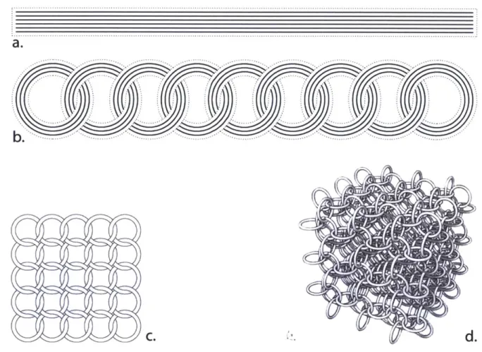
Figure 5 Concept Diagram for Digital Composites - chained continuous fiber loops
As an application of fiber composites, the core concept is that a chain of discrete fiber composite parts can be close to the strength of a monolithic part, and would have advantages with manufacturing processes, serviceability, and reusability, in addition to the tunability and
extensibility that are general goals of digital materials.
The structure can therefore be thought of as a chain of parts, each transferring load through load bearing holes with continuous circuits of fiber around their perimeter. This way, the structure is an assembly of linked tiles that are individually tuned through their fiber layup, so that forces are transferred between the tiles, rather than having continuous fibers span entire macro-structures.
A major difference between conventional cellular solids and digital cellular solids is the
presence of many reversible connections, the behavior of which will be accounted for in later chapters. The primary benefit is the manufacturability of complex geometries that result in mechanical property scaling laws that are quite different to those of both stochastic foams and previously reported non stochastic ultra-light materials. While these connections can also be used to design novel structural behavior, they do come at an overall density cost. I will show, here, that this density cost is minimal when employing this strategy for ultra-light materials.
Digital Materials, in general, employ a finite number of types of simple discrete components which can be assembled to large structures according to local-only rules, which makes them good candidates for trivial adaptation to various shapes at a large scale. In addition to simple spatial distribution of regular lattices, precise distribution of parts for a given structural function may also be automatically accomplished through algorithmic distribution throughout a prescribed volume, according to external constraints (Hiller & Lipson 2012). Other strategies for tuning of mechanical properties include introducing voids, varying part ratios, varying core geometry, and introducing kinematically indeterminate lattice states (Guest & Hutchinson 2003).
Figure 6 part size hierarchy, core structural variation, introduction of voids as methods of structural tuning
Kenneth C. Cheung, PhD Thesis, Media Arts & Sciences, MIT Page 26
For complex shapes, Digital Materials provide a potential "tool-less" (or "less-tool") assembly process, where the geometry of the parts being assembled provides the dimensional constraints required to precisely achieve complex forms. This does not rely on each part being very precise, but instead relies on specific knowledge of the nature of the errors that do occur (part production must be a stochastic process). For instance, a system whose assembly over-constrains elastic components can provide positioning with much higher precision than that which is contained within the shape of any single component.
Reversible interlocking assembly allows deconstruction and reuse of individual
components. In addition, service life of larger assemblies can be greatly increased by the ability to selectively replace small portions of a structure. While the assemblies in this study have been assembled by hand, a digital assembler may be considered critical to the viability of digital fabrication, in order to have practical advantages over existing manufacturing technologies - with regard to factors such as cost and time, given the increased resolution. The suggestion here is that assemblies should be produced from orders of magnitude more individual parts than are typically used in manufacturing, today. The key to making this plausible might be robotic digital assemblers that can build structures much larger than themselves, and that work in parallel. An important attribute of digital materials that makes this possible is the finite and low number of part types and connection schemes. This chapter addresses the design of Digital Composites, in terms of Geometry and Mechanics.
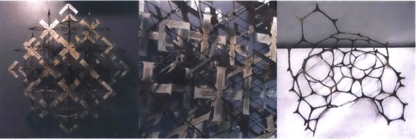
Figure 7 snap fit flexural lattice studies: left, middle, tensegrity crystal; right, hyperbolic/geodesic surface kit
Geometry
The goal of this section is to present geometric theory for digital material assemblies as cellular solids. The primary questions surround the effect of geometric design on the relative density of the final structure. Purely geometric effects on mechanical behavior will be introduced, but addressed in more detail in the following section. Here, I look to determine global
characteristics in structures as defined by local geometry.
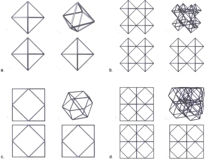
The versatility of the digital material approach, in terms of lattice geometry, is loosely illustrated by the scope of designs apparent in Figure 1 and Figure 8. The former two figures show a variety of four-connected units in orthotropic arrangements, topologically similar to the design that is shown in the left side of Figure 8. The designs in the latter figure are snap-fit structures that utilize flanged members to increase torsional rigidity. An idealized isotropic lattice structure is shown on the middle and right side of Figure 8, with regular twelve-connected nodes forming a hexagonally close packed (HCP) structure.
Figure 8 snap fit flexural lattice studies: left, simple cubic lattice with two part scheme; right, 12 connected octet truss with three part scheme
While the parts for the schemes above are fabricated as two dimensional shapes, and there are relatively few different shapes per scheme (two for the orthotropic scheme, three for the HCP scheme), there are many parts per spatial unit (twelve for the orthotropic scheme, thirty for the HCP scheme). Given that iterative quantity is required for bulk characterization as a cellular solid, and considering that every connection incurs assembly cost (structural cost/benefit depends on
Kenneth C. Cheung, PhD Thesis, Media Arts & Sciences, MIT Page 28
structural objective), the case study that I address in most detail is a simpler design, such as the one shown in Figure 9.
Figure 9 two part scheme for cuboct truss
At the heart of the original design problem is the decomposition of a regular lattice into self similar units that tessellate throughout space. The most basic decomposition separates every node and strut member in the lattice into individual units, requiring two connections per strut member and m connections per node, for a lattice with m-connected nodes. When designing a scheme for digital materials, it is advantageous to find ways to partition this lattice into tessellating units that contain multiple strut members each, for practical reasons as well as mechanical reasons that will be discussed in the next section. Considering that the space of all reversible connections used in engineering are fair game for adoption as connection strategies, we may see this as a very high dimensional problem, wherein certain types of solutions for one factor may constrain the possible solutions for another. This does not stop us from examining the relative importance of a few of the high level geometric decisions that need to be made when embarking on the design process. In particular, I will look at density in relationship to connectedness, starting with two dimensional systems and then expanding to three dimensional systems, for clarity.
Our oldest record of the two dimensional minimal edge packing problem dates back to
36BC, from Marcus Terentius Varro (Hales 2001), and is commonly referred to as the Hexagonal
Honeycomb Conjecture. While it has been widely assumed to be true for lack of a counter example, this goal - of proving the most efficient division of a plane into similar units - stood unsolved until
1999 (a proof by Thomas Hales). There are three obvious regular polygonal area filling tilings of a
plane -triangles, squares, and hexagons. However, as long as a pattern is repeating so that a small family of parts can be assembled to produce the final pattern, such as a kagome lattice constructed
from triangles (Connelly et al 2008), the geometry is fair game for digital materials. After the proof of Hales, we have reason to believe that hexagonal tiling provides the most space per unit edge, whether produced by regular tiling or not, and therefore the lowest density. Before considering the relationship of density to mechanical attributes, I will proceed with a short exploration of this density question.
Given a polygonal lattice of z-connected nodes and the corresponding strut members of equal length, what is the effect of connectedness on density? Intuitively, we can assume that low connectivity will give us low relative density, but just how much does high connectedness affect this relative density?
Kenneth C. Cheung, PhD Thesis, Media Arts & Sciences, MIT Page 30
An Estimation of an Upper Bound on the Perimeter to Area Ratio of Not-Necessarily-Space-Filling Two-Dimensional Grids Composed of Polygons
Consider a tiling on a Euclidean plane, which consists of straight strut members of length
(1), connected at each end with nodes of arbitrary connectedness (z). Assume that the angles (a) between strut members at each node are equal, so that:
2Tr
(X
=
- Equation 3z
Further, to enclose maximum volume per polygon, assume that the tiling consists of convex regular polygons with a number of sides (n), which can be determined from the strut member angle:
21r
n = 2n (for Euclidean plane, n = 2rT / (T -a) Equation
-- a
2
which can be expressed in terms of connectedness (z):
n = 2 - = - - Z Equation
2 Z 2 z
which describes the identity relationship between sidedness and connectedness of this model: the higher the connectivity, the lower the sidedness of the constituent polygons, and vice versa:
2z 2n n = - and z= - Equation z-2 n-2 4 5 6
In order to estimate the density of a grid composed of these polygons, we need to estimate the area that each polygon might represent in a given tiling. I'm looking to make a scaling argument that addresses the general sensitivity of the perimeter to area ratio to changes in constituent variables. For this, we may start by determining their characteristic length. Given the number of sides (n), we can determine the largest characteristic dimension (a line, d, through the middle of the polygon), by starting from one side of this line and summing the components (6) of each polygon side (of length
1) that are parallel to the line, considering the progression of the angle (P) relative to the line, for half of the sides (n / 2):
d
= Q/2(Si) Equation 7Where
6i = I cos
Pi
Equation 8And
1 1 27r(4i-2-n)
-21(i 2 - 1) - 1(2i 2 - 1)a = 2w(1 + i(m - 2) - m)m = 4
2 4nl Equation 9
such that:
n/2 Cos 7(4i-n-2)
i=1 2n
Equation 10
Kenneth C. Cheung, PhD Thesis, Media Arts & Sciences, MIT Page 32
which converges to (nl /T) for very large numbers of sides (n). We also see that this convergence relates to the classical formula for the circumference of a circle:
nl = Td Equation 11
Since we know that perimeter length is proportional to nl, and area is proportional to d2, then
minimization of perimeter to area goes by n/d 2. Looking at n/d 2 per n, for unit edge length (1 = 1),
clearly shows that the effect of connectedness (and sidedness) on perimeter to area - is within an order of magnitude, and insignificant if relative edge length (1) can be varied across orders of magnitude.
These results are applicable to the design of two dimensional cellular materials (i.e. digital cellular skins), when considering load transfer across a surface (e.g. hoop stress). For now, I will move on to the three dimensional case.
Extension of these methods to examine our three dimensional problem (confined to the examination of the effect of connectedness on density) is fairly easy, if somewhat less precise (due to the addition of geometric assumptions about distribution of strut members in the third
dimension). Our oldest record of the three dimensional minimal packing problem is considerably more recent than the two dimensional honeycomb problem, dating back a little over a century (Kelvin 1887). The Kelvin Conjecture addresses maximally space efficient bubble packing, with tetrakaidecahedrons arranged in a body centered cubic packing. Very recently, the Weaire-Phelan structure (Weaire & Phelan 1993) was presented as a counter-example, with two types of cells and an area to unit volume that is more efficient than that of the Kelvin structure, by a very small amount (0.3%). The problem of what is the most efficient structure remains unsolved.
While there are only a few regular polyhedral space-filling tilings, we may consider our three dimensional problem as being analogous to the two dimensional one. As in two dimensions, as long as a pattern is repeating so that a small family of parts can be assembled to produce the final pattern, the geometry is fair game for digital materials. With the efficacy of its use in modeling stochastic foams, and a belief in energy minimization in nature, we might believe that four
connected (e.g. the Kelvin structure) tiling provides the most space per unit edge, and therefore the lowest density for structures consisting of all equal length strut members. Once again, before
considering the relationship of density to mechanical attributes, I will proceed with a short exploration of this density question, this time in three dimensions.
Given a polyhedral lattice of z-connected nodes and the corresponding strut members of equal length, what is the effect of connectedness on density? Intuitively, we can assume that low connectivity will give us low relative density, but just how much does high connectedness affect this relative density?
Kenneth C. Cheung, PhD Thesis, Media Arts & Sciences, MIT Page 34
An Estimation of an Upper Bound on the Total Edge Length to Volume Ratio of Three-Dimensional Lattices Composed of Polyhedrons
Consider a tiling in space, which consists of straight strut members of length (1), connected at each end with nodes of arbitrary connectedness (z). Take the simplification that the strut
members are distributed throughout at least two discrete planes intersecting each node, so that the angles (a) between strut members are at least:
4w
a = 21T / (z / 2) = - Equation 12
To enclose maximum volume per polyhedron, assume that the tiling consists of convex regular polyhedrons with maximum possible characteristic dimensions defined by a polygon with a number of sides (n), which can be determined from the strut member angle:
2n
n = 2T / ((27T / 2) -a) = n = Equation 13 which can be expressed in terms of connectedness (z):
2w 2 nz z
n- 4-
4-7-- 1-- 4 2
z z
Equation 14
which describes the relationship between sidedness and connectedness of this model: the higher the connectivity, the lower the sidedness of the constituent polygons, and vice versa:
2z 4z
n = - and m
=-z-4 z-2 Equation 15
In order to estimate the total strut member length to volume ratio of a lattice composed of polyhedra whose characteristic length is described by these polygons, we may estimate the total number of strut members as the square of the number of sides in one of these theoretical
constituent polygons, and the volume as the cube of this characteristic length that is calculated from this polygon. Given the number of sides (n) for each polygon, we can determine the largest
characteristic dimension (a line, d, through the middle of the polygon), by starting from one side of this line and summing the components (6) of each polygon side (of length 1) that are parallel to the line, considering the progression of the angle (P) relative to the line, for half of the sides (n / 2):
where 8i = 1 cos fi Equation 16
1 (2+i(z-4)-z)T 1 =-(4i - 2-n)nwT =(-1 + i) - (2i - 1) z z 2
d
n/2 ( C 1r(4i-n-2) i=1 (2n Equation 17 Equation 18which is identical to the 2d case, since this expression only compares d and n. Given the assumption that total perimeter strut member length is proportional to n2, and volume is
proportional to d3, then minimization of total strut member length to volume is proportional to
n2/d 3.
Kenneth C. Cheung, PhD Thesis, Media Arts & Sciences, MIT
d
=(
And
such that:
2z 2 (Yr)(-2+4i-( 2z
((
)2)(Cos
2(2 -4+z)
3 Equation 19i=1-4z
The contour of n21/d3 per node connectedness (z), for unit edge length (1 = 1), suggests that like the 2d case, the effect of connectedness on the total strut member length to volume ratio - is also within an order of magnitude, and therefore also insignificant if relative edge length (1) can be varied across orders of magnitude.
These estimation results give us some confidence in retaining the design freedom to choose lattice geometries without straying into an area of the design space where obtaining desirable relative density is unlikely. Focusing further on actual design parameters, I next look towards a general scaling law that now takes into account dimensions such as strut member length (1) and thickness (t). This will be an expansion of known scaling laws for analytical modeling of cellular solids, with the addition of terms to account for the connections in a digital material, which we may assume to occur at the nodes in the lattice. We also consider aspect ratio as p = t/l. Relative density is conventionally defined as (p*/ps), where p* is the mass of the lattice divided by the total
bounding volume (v*), and ps is the density of the constituent solid material (i.e. the mass of the lattice divided by only the volume of the constituent solid material vs):
p = t/l (aspect ratio, t=thickness, l=length).
d = kpl (pitch, kp = length constant)
p*/ps = (m/v*)/(m/vs) = vs / v* (Relative density)
Equations 20
We may also define the characteristic dimension of the repeating cell as pitch, d, which is proportional to the length of each strut member according to the lattice geometry. As such, the bounding volume v* is proportional to d3. The volume of the solid material per cell is composed of the sum of the volumes of the strut members and connections, which for square prism strut members may be defined as t2
1 and ket3, respectively (note that the size of the connection does not
depend on 1, as the governing factor in connection design is stress, and therefore maximally scales with the cross sectional area of the strut member).
v* oc d3
vs = nivstrut member + ncvconnection
(ni = number of strut members per unit cell, nc = number of connections per unit cell)
Vstrut member = t2l
vconnection = kct3 (no dependence on 1)
vs= nit2l + ncket3
vs / v*
ac
(nit 2l)/d 3 + (nckct 3)/d 3 = (nit2
l)/(kpl)3 + (nckct3)/(kpl)3
Equations 21
This gives us the relationship of relative density to various factors:
p*/ps = (ni/kp3)p2 + (nckc/kp3)y3
p*/ps oc <2
Equations 22
We see here, that relative density scales linearly with the number of strut members per cell, number of connections per cell, and the connection size factor. The contribution of the connection distribution, as defined by a given geometry, to relative density, scales with the cube of the aspect ratio of the strut members, and is therefore relatively unimportant. The governing side of the equation comes from the strut member contribution constants, but these scale with the square of the aspect ratio of the strut members. This suggests that the most effective geometric strategy for reducing the relative density is to reduce the ratio of strut member thickness to length. Pitch factor kc can be understood to encapsulate the total strut member length per volume, which we expect from the previous estimation to not vary by very much between lattice geometries. To validate this understanding of the design space (that strut member aspect ratio is the most important factor in obtaining lattices with low relative density), we proceed with precise calculations of the relative density of four candidate lattices, of varying connectedness. These are, in increasing order of connectedness: the Kelvin structure with four connected nodes, a simple cubic lattice with six connected nodes, a simple cubic packing octahedral/cuboctahedral lattice (henceforth referred to
Kenneth C. Cheung, PhD Thesis, Media Arts & Sciences, MIT Page 38
as a "cuboct" truss) with eight connected nodes, and a simple rhombic packing 2 tetrahedron 1 octahedron lattice, known as an "octet" truss (Fuller 1961), with twelve connected nodes. Given
p*/ps oC C1<p2 + C2< 3
, we find the constants C1 and C2, shown in the table below.
Table 1 Properties of Candidate Lattice Geometries
connectedness cell connections strut strut connection volume per cell members member scaling
per cell scaling constant constant m v* nc ni C1 C2 Kelvin 4 (16N2)13 12 24 (3v2)/4 3/(442) Structure Simple Cubic 6 13 1 3 3 1 Cuboct 8 (2-2)13 3 12 342 3/(2v2) Octet 12 (42/2)13 1 6 62 N2
Given that the connection scaling constant, C2 is not significant, since it scales with the cube
of the strut member aspect ratio, examining the strut member scaling constant, C1, should give us
some indication of the relative impact of strut member length and width for these actual lattice designs. This constant essentially gives us a measure of the volume contribution of the strut members, to the overall volume. In this version of the model, it also can be taken to account for some of the "double-counted" material that is a result of the method of counting total strut member volume (Gibson & Ashby 1988). It does not take into account the increasing spatial complexity of the problem of designing reversible connections, with increasing node connectedness. This is a somewhat different type of problem, which will be left to future work.
It is hoped that these results provide a useful description of the problem space of designing lattices with relative density as a figure of merit. Characteristics such as lattice type, connectivity, and connection size all contribute to the final relative density, with proportional scaling that is within an order of magnitude. In particular for ultra-light materials, the most significant changes in relative density are made by changing the aspect ratio of the strut members.
Mechanics
In stochastic foams, conventional models typically consider the average connectedness to be four, and strut members effectively meeting at midpoints of other strut members, resulting in characteristic behavior that is dominated by transverse beam bending (Gibson & Ashby 1988). This results in an overall relative modulus that is expected to be proportional to the square of the relative density, for open cell foams:
E* p2
- C P Equation 23
Es Ps2
It is known that it is possible to improve upon this, with non stochastic geometry (Deshpande et al 2001), and we expect to do better, accordingly. In an ideal sparse structure, E/Es oc (p/ps), when loads are perfectly distributed so as to be purely axial on all elements in the structure. In
compression, this is limited by member buckling, beyond the point at which infinitesimal offsets in the loading of an element will produce a bending moment that will receive further contribution from the axial load. In tension, such a proportional relationship is geometry dependent, and relies on the degree of mechanical constraint of each element, as afforded by the lattice geometry (Maxwell 1864; Calladine 1978), as well as the ability to efficiently transmit bending moments between elements (Broedersz 2011).
A key point here is a small departure from the bulk of the cellular solids literature, which
has mostly considered two states of structures: those whose elements are maintained in pure axial loading (therefore dominated by stretching behavior), and those which fall into bending dominated behavior (and therefore consider negligible stretching contribution). A clue as to the practical existence of a third state comes from the statistical mechanics literature, as pertains to the mechanical behavior of interconnected networks of proteins. This class of materials, such as actin meshworks, microtubules, and fibrin and collagen matrices, is known to display higher strength and stiffness than their structural connectivity predicts with traditional framework rigidity criteria. While the exact phenomena that explain this are still under debate, pure mechanical models that
show the ability of stretch-bend coupled systems to display proper behavior seem promising (Broedersz 2011). This relies to some degree on the relative strength and elasticity scaling of microscopic interactions for these materials (e.g. proteins), which form networks with a large
Kenneth C. Cheung, PhD Thesis, Media Arts & Sciences, MIT Page 40
disparity in bond strengths (Jacobs et al 2001). In any case, if this intermediate phase of mechanical structure exists, then we should be able to show similar behavior at the macro scale.
There are two main reasons to choose a stretch-bend coupled material over a stretch dominated material. The first is versatility - if we can show this intermediate mechanical mode, then tuning parts to the better characterized bending and stretching dominated modes should be relatively easy. The second reason is failure mode - we expect that a stretch dominated fiber composite cellular solid would fail in a brittle fashion, and we are interested in knowing what the macro-scale failure mode of a stretch-bend coupled material looks like. A possible third reason has to do with the connections -when not building parts from a material such as carbon fiber, it may be helpful for the design and relative density to avoid pure axial loading of the joints, assuming that strength and stiffness requirements can be met without this.
Consider a model of a sparse digital material lattice as its true geometry, composed of members of length 1 and square cross section of side t. The relative density p/ps, and the second moment of area of a member, I, are related to the dimensions t and 1 by:
P - Pc (connection contribution) + P (ligament contribution)
Ps Ps Ps
p t2 t2
I = t4/12 for square cross section; I oc t4
Equations 24 where
p = mass density of structure
ps = mass density of constituent solid
t = strut member thickness
I = strut member length
for a Kelvin structure, Cc = 342/4, and C1= 3/(4V2) (Gibson & Ashby 1988)
for a cuboct structure, Cc = 312, and Ci = 3/(2N2)
Equations 25 For conventional foams and flexural functional composite part types, transverse beam bending deflection describes the primary response mechanism, modeled as beams that are simply supported at both ends and loaded in the middle (Gibson & Ashby 1988).
8
o-EeI
8 = 8hending oc F 12/E51 (for low P/Ps)
Equations 26 Where
6 = change in length
E = modulus of elasticity of structure
ES= modulus of elasticity of constituent solid
a = F/Ac
E = /Lc
for a Kelvin structure, Ac = 12/2, and Lc = 12/2 for single beam (Ac = 212, and Lc = 142 for entire cell)
for a cuboct structure, Ac = 812, and Lc = 1W2/2 for single beam (Ac = 3212, and Lc = 4142 for entire cell)
Equations 27 from which E =
a/E
gives an expected relative modulus of:Kenneth C. Cheung, PhD Thesis, Media Arts & Sciences, MIT Page 42
E/Es = (FLc/Ac6)/Es
for a Kelvin structure, E/Es = (V2)((F/1)/Es) for a cuboct structure, E/Es = (11(8-2)) ((F/1)/Es) thus, we may assume E/Es = Cg((F/16)/Es)
Equations 28 And F (t 2 E E/Es = Cg((F/1)/Es OC Cg 2 0(Fl /Es)Es oC C Equation 29
assuming, from above, that p/ps oc t2 /12
and I oc t4,
E/Es oc t2
/12
oc (p/ps)2 Equation 30
In contrast, the ideal loading condition for any subunit of the system is purely axial, so that
E/Es oc (p/ps). It is known that this can be effected by high degrees of co-constraint, provided by lattice geometries with high connectivity (Warren & Kraynik 1988). This effect is intuitive upon
examination of lattice types, as lattices with higher connectivity tend to connect strut members in
such a way to produce axial loading of the individual strut members in the structure. Generally speaking, it is seen that lattices with higher connectivity at each node are better able to constrain
the load paths, accordingly. In contrast, a lattice with low connectivity, such as the Kelvin structure,
lacks any direct axial loading of material throughout the structure, is in some ways an effective
representation for the myriad stochastic cellular solids currently used in engineering practice, and exhibits the quadratic modulus scaling law that makes engineered cellular solids more ideal for
applications such as energy absorption, than those requiring high stiffness. If we can design the
lattice for a cellular solid, because we are assembling it from discrete components, then we can
prescribe a degree of connectivity that can result in these load pathways balancing through the
material as necessary. The important summary suggestion is that geometrically defined constraints can greatly influence the scaling relationship between mechanical material properties and relative density.
relative density
/
relative modulus
-- -- -- -A law --- 1.5 law A 2 law ...-- A31aw 0 0.2 0.4 0.6 0.8 relative density 1
Figure 10 Relative Density vs Modulus Scaling Curves
This emphasis on end constraints for strut members leads us to another critical role of the connections. The use of many smaller parts to assemble a large part allows for the use of elastic averaging (Slocum 2003) in order to reduce error in manufacturing methods. When many parts are used to locate a single feature, with enough elastic compliance to adjust to small inconsistencies in the location of the feature, the effective location of the feature will be the average of the individual constraints provided by the surrounding parts. When this process is performed correctly, this average location can be more precise than the process used to fabricate the individual parts. The original per-part error must be within a certain threshold for a given system.
By the same rules, when forces are effectively distributed throughout an assembly of
smaller parts, tolerances on strength requirements may be reduced as the observed bulk strength
Kenneth C. Cheung, PhD Thesis, Media Arts & Sciences, MIT 5 0 E is 1 0.9 0.8 0.7 0.6 0.5 0.4 0.3 0.2 0.1 0 Page 44
of the assembly will be a result of this distribution. This is also naturally enabled by natural coupling of elasticity to strength, whereby weaker and more elastic components transfer load through stronger and stiffer components, while still contributing to overall stiffness.
The major components at hand, in a sparse digital material system as I have defined it, are the strut members and the connections. The properties of either are a question of design. When considered as a continuum, second order material properties will result from the behavior of both. Whether or not the behavior of either is responsible for the characteristic behavior of the
continuum, for a given stress regime, is once again a matter of design. As such, the connections may be designed such that the aft curve of the connection (a(E)c) has a particular relationship to the a/E curve of the most elastic within-part strut member (a(E)p).
II N. Li4 II bq e=I/L t5 /EL e=I/L
e1/L
Figure 11 hypothetical designed digital material stress strain curves