Publisher’s version / Version de l'éditeur:
Vous avez des questions? Nous pouvons vous aider. Pour communiquer directement avec un auteur, consultez la première page de la revue dans laquelle son article a été publié afin de trouver ses coordonnées. Si vous n’arrivez Questions? Contact the NRC Publications Archive team at
[email protected]. If you wish to email the authors directly, please see the first page of the publication for their contact information.
https://publications-cnrc.canada.ca/fra/droits
L’accès à ce site Web et l’utilisation de son contenu sont assujettis aux conditions présentées dans le site LISEZ CES CONDITIONS ATTENTIVEMENT AVANT D’UTILISER CE SITE WEB.
[Proceedings of the Conference], 2018-09
READ THESE TERMS AND CONDITIONS CAREFULLY BEFORE USING THIS WEBSITE.
https://nrc-publications.canada.ca/eng/copyright
NRC Publications Archive Record / Notice des Archives des publications du CNRC : https://nrc-publications.canada.ca/eng/view/object/?id=01bee43d-b7e2-4c28-85ec-6f29459023a8 https://publications-cnrc.canada.ca/fra/voir/objet/?id=01bee43d-b7e2-4c28-85ec-6f29459023a8
NRC Publications Archive
Archives des publications du CNRC
This publication could be one of several versions: author’s original, accepted manuscript or the publisher’s version. / La version de cette publication peut être l’une des suivantes : la version prépublication de l’auteur, la version acceptée du manuscrit ou la version de l’éditeur.
Access and use of this website and the material on it are subject to the Terms and Conditions set forth at
SNAP RTM: a cost-effective compression RTM variant to manufacture
composite component for transportation applications
SNAP RTM: A COST-EFFECTIVE COMPRESSION-RTM VARIANT TO
MANUFACTURE COMPOSITE COMPONENT FOR TRANSPORTATION
APPLICATIONS
Loleï Khoun, Paul Trudeau
National Research Council Canada
75 blvd. de Mortagne, Boucherville, QC, J4B6Y4
Abstract
The Corporate Fuel Average Efficiency (CAFÉ) regulation requires average fuel consumption of cars to increase from 37.8 mpg (6.2 L/100 km) to 54.5 mpg (4.3 L/100 km) by 2025. One solution to help reach this target is vehicle lightweighting. As a reference, a 10% reduction in vehicle weight can result in a 5 – 8% reduction of fuel consumption. Among the lightweight material alternatives, fibre reinforced composite materials are believed to enable car body-weight reductions of 25% to 50%, weight reduction that cannot be obtained with lightweight metals alone. From an industrial point of view, process cycle time and cost are the main barriers to a wider use of fibre reinforced composites in mass produced vehicles, as current high performance composite manufacturing processes do not meet the 2 to 5 minutes cycle time desired by the transportation industry for the production of large series components. In order to benefit from the performance of advanced composites needed to achieve significant reductions in vehicle weight, it is then necessary to develop rapid and cost-effective processing techniques adapted to these materials.
In recent years, material suppliers have been reducing the cure time required for thermoset resins that have helped to shorten cycle times targeted by the automotive industry. Among the manufacturing technologies available to produce high performance composites parts, liquid moulding technologies appear to have some potential to successfully introduce those rapid cure resin systems at faster production rates. In this study, a cost effective variant of the Compression-RTM process has been developed to manufacture high performance composite plaques. The injection and compression parameters were studied and compared to traditional RTM moulding: cycle time, part quality and part mechanical performance. Results validated the use of low cost / low pressure injection equipment combined with a static mix head and innovative tool design to manufacture composite plaques within cycle times targeted by the transportation industry.
Introduction
Background
Continuous fibre reinforced composites used for structural lightweighting solutions are starting to change the transportation industry. In the automotive industry, OEMs (original equipment manufacturers) are using more and more composite solutions to redesign their vehicles in order to improve vehicle performance and increase fuel efficiency to meet the Corporate Fuel Average Efficiency (CAFÉ) regulation, requiring average fuel consumption of cars to decrease from 6.2 L/100 km to 4.3 L/100 km by 2025. As a reference, a 10% reduction in vehicle weight can result in a 5 – 8% reduction of fuel consumption [1-2]. In addition, composite materials can also offset weight increases resulting from autonomous/electrification strategies, thus improving battery range and or mileage. The truck industry, currently uses about 20% of the vehicle fuel in North
America, and since 2016, heavy trucks have to comply with new emission regulations [3]. Using composite lightweighting solutions, truck manufacturers will not only be able to reduce their fuel consumption and GHG emission, but will also reduce operating costs with lower fuel expenses, as fuel accounts approximately for 50% of the total operating costs. Maintenance costs will also be reduced as composite materials don’t corrode and overall payload-to-mass ratios will be increased. For example, reducing heavy truck weight by 1363 kg could save a truck fleet operator up to 900 L of fuel each year. Similarly, bus manufacturers would benefit from lightweighting solutions to reduce fuel expenses, increase passenger-to-mass ratio, and improve the mileage efficiency of hybrid/electric bus fleets.
The main barriers to a wider adoption of fibre reinforced composites in mass-produced vehicles are [1]:
1. Cost: The transportation industry is a very cost-sensitive; carbon and other advanced fibres are several times more expensive than steel on a pound to pound comparison.
2. Process time: Current advanced composite manufacturing processes don’t meet the cycle time targeted for medium to high production rates (2 – 5 minutes for automotive applications and 5 – 10 minutes for ground transportation).
In order to benefit from the performance of advanced composites to achieve significant reductions in vehicle weight and operation cost, it is then necessary to develop rapid and cost-effective processing techniques and assembly scenarios (part integration, hybrid parts with metallic inserts, etc.) adapted to these materials. Accessibility to cost-efficient composite solutions compared to metallic solutions would help these high performance materials better penetrate the ground transportation market.
In recent years, material suppliers have developed rapid cure thermoset resins meeting shorter cycle times targeted by the ground transportation industry. Among the manufacturing technologies available to produce high performance composite parts, Resin Transfer Moulding (RTM) and prepreg technologies appear to have the most potential to successfully introduce these rapid cure resin systems at these production levels. In the automotive industry, European OEM BMW already capitalized on the potential of rapid cure epoxy resin using the High-Pressure RTM process for its newer model of vehicles (i3, i8, and series 7) and it is closely followed by Volkswagen, Audi and Porsche, while in Canada, Magna Exteriors developed a rapid cure prepreg system to demonstrate mass savings of 20% - 30% with the development of the first compression moulded carbon fibre prepreg hood for mass production [4]. Dow Automotive System and Ford Motor Company also developed and tested a rapid cure prepreg moulding and wet compression moulding to make a composite B-pillar [5]. In the truck industry, the SuperTruck program launched by the US Department of Energy, aiming at developing Class 8 tractor trailers with 50% greater fuel efficiency, validated the use of carbon reinforced composites for roof, hood and side fairing applications. Building on the program outcomes, a SuperTruck II program is now ongoing, focusing on the development of cost-effective solutions to improve heavy-truck freight efficiency improvements by more than 100%. This program highlights the need for affordable processes for manufacturing composite structures. So far only a few bus manufacturers have opted for the use of composites materials as lightweighting solutions. For example, Proterra developed a full composite bus body for its zero-emission electric bus. Although interest is growing, minimal information has been publically disclosed and little work has been done in North America on the development of these rapid processes for medium to high volume production.
While the RTM process has been extensively studied for aerospace applications, the use of rapid cure resins to reduce cycle time is new and raises several technical challenges. Composite processing involves different interconnected phenomena; resin flow, resin cure, heat transfer and
creation of residual stresses, all affecting the final performance of the composite structure. These phenomena usually happen sequentially; the resin first fully impregnates the preform and then cures. This is well understood with conventional RTM. However, with rapid cure resins, impregnation and curing reaction occur almost simultaneously which can lead to impregnation defects (dry spots, voids), unbalanced residual stresses and dimensional instabilities or low mechanical properties [6-8]. The lack of data on raw materials, processing parameters and part performances, tool and part design, preform handling automation as well as process modelling, combined with material and equipment cost, remain a major barrier to their implementation in production.
SNAP Composites Processes
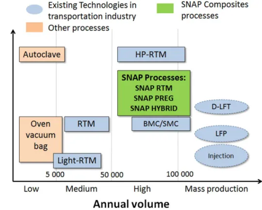
The NRC has recently developed improved variants of RTM and Prepreg Compression moulding processes and have named these processes SNAP RTM, SNAP PREG and SNAP HYBRID with the use of rapid cure resins, to evoke the need for Short Novel Affordable Processes for composite manufacturing. Figure 1 illustrates the positioning of SNAP processes, as compared to conventional composite processes.
Figure 1: Positioning of SNAP processes compared to other composites manufacturing processes
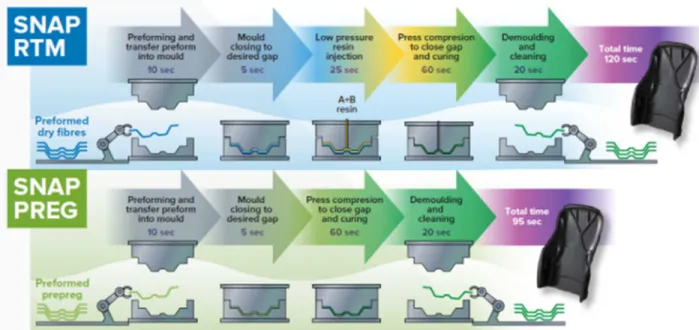
The SNAP processes are depicted in Figure 2. SNAP RTM is a cost-effective variant of Compression-RTM process. It involves injecting a liquid resin (ex: epoxy, polyurethane, polyester), using a low pressure injection equipment, through a dry preform placed in a closed-mould. During the injection, the mould is not fully closed, but remains open to a desired gap allowing the resin to flow faster on the top of the dry preform and then through the preform by compression during mould closing. This requires the use of specific tooling design to insure the
tool remains leak-proof during the injection. SNAP PREG or Compression-Prepreg consists of laying a low-cost prepreg preforms in a closed mould and uses compression movement of the press to activate the resin flow within the prepreg. In addition, SNAP HYBRID uses a combination of discontinuous Sheet Moulding Compound (SMC)-type reinforcements with low-cost prepregs to add local geometric features such as ribs or variable thickness to a high performance part.
Figure 2: SNAP RTM and SNAP PREG process. SNAP HYBRID is the same process as SNAP PREG with the preform being a combination of low-cost prepreg and SMC-type local reinforcements.
The objective of these processes is to reduce manufacturing costs by:
Minimizing capital investment by using low pressure injection RTM systems combined with low pressure consolidation using vertical presses
Decreasing tooling cost by using innovative multi-process tool designed to work both for Compression-RTM and Compression-Prepreg processes
Automating key processing steps such as preforming, loading and injection sequences to reduce cycle time
Consolidating multiple features in a single part as well as attachment points and complex edge details.
This paper focuses on the SNAP RTM process. Equipment and process protocols used to manufacture rapidly high performance composite plaques are described. The effect of some injection parameters (mould gap, injection pressure and vacuum) on the cycle time, part quality and part mechanical performance is investigated. The benefits of SNAP RTM process are highlighted.
Experiments
Materials
SNAP RTM trials were carried out using EPIKOTETM resin 05475 and EPIKURETM curing
agent 05500 from Hexion and ZoltekTMPX35 (0/90) MD 300 carbon fabrics. Composite panels
were manufactured with a [0/90]5sstacking sequence. Carbon fibre dry reinforcements were first
preformed using EPIKOTE Resin Trac 06720 binder from Hexion prior to injection.
Resin characterization
Prior to processing experiments, the cure kinetics and rheological behaviour of the rapid cure epoxy resin were characterized using Differential Scanning Calorimetry (DSC) and rheology with parallel plat geometry. DSC tests were performed under dynamic conditions and isothermal conditions at 80ºC, 100ºC, 110ºC and 120ºC. Rheology tests were carried out under the same isothermal conditions to measure the gel time at those different curing temperatures.
Equipment
A built-to-specification low pressure flow controlled RTM injection equipment from Polytec-Group (Figure 3-a) was used to inject the rapid cure resin from Hexion. The equipment was designed to handle variable resin chemistries with variable mixing ratios, such as epoxy, polyurethane and vinyl-ester, with injection pressures up to 50 bars and flow rates up to 8 kg/min. The temperature of the tanks, injection lines and mix head can be controlled up to 90ºC. The resin (EPIKOTETM 05475) was heated at 50ºC while the hardener (EPIKURETM 05500) was kept at
room temperature. The mix head with static mixer was connected to a hydraulic injection valve (Figure 3-b), designed by NRC, and mounted on the mould. The opening and closing of the hydraulic valve is synchronized with the injection and cleaning sequences.
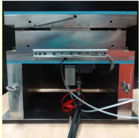
A P20 steel plaque tool (Figure 3-c) was mounted on a 1250 tons compression press from PEI (Pinette Emidecau Industries). An innovative plaque tool, conceived by NRC, was designed, to be capable of demonstrating both SNAP RTM and SNAP PREG processes. Plaque dimensions are 350 mm x 350 mm with thickness ranging from 1 mm to 10 mm. For SNAP RTM process, the injection gate is located at the center of the mould with peripheral vent. A pinch area was designed in the mould by reducing the thickness at the plaque edges. This pinch area holds the preform in place and minimizes fibre movement during the injection.
a) Polytec-Group low pressure injection
equipment
c) NRC 350mmx350mm Plaque tool
d) Hydraulic valve connected to the mould
Figure 3: SNAP RTM equipment Mechanical tests
Tension tests (ASTM standard D3039) and 3-point bending tests (ASTM standard D790) were performed to assess the influence of the processing conditions on the mechanical properties of the composite panels. An Instron 5582 testing machine was used with a load cell of 100 kN with the traction fixture for the tensile tests. The cross head speed was fixed at 2 mm/min. Aluminum tabs were added to the tensile specimens in order to avoid stress concentration at the grip fixture. The composite flexural properties were measured using the three-point bending fixture with a 25 kN load cell on an Instron 55R11213 testing machine. The loading nose and the radial support had a diameter of 6 mm and 3 mm respectively. Specimens were cut with a span-to-depth ratio of 40:1, leading to a cross head speed 8 mm/min. Six samples per moulded part were tested for each mechanical test.
Glass transition temperature (Tg) was measured by Dynamic Mechanical Analysis following
ASTM D7028. Samples were tested in three-point bending, at a frequency of 1 Hz and a strain of 0.05%. Heating rate temperature was set to 2ºC/min from 30ºC to 200ºC.
Part quality
Part quality was first assessed visually to locate any impregnation defect such as dry spots, uncomplete impregnation or void. Then, the quality of the impregnation within the preform was observed under optical microscope.
Results and Discussion
Processability
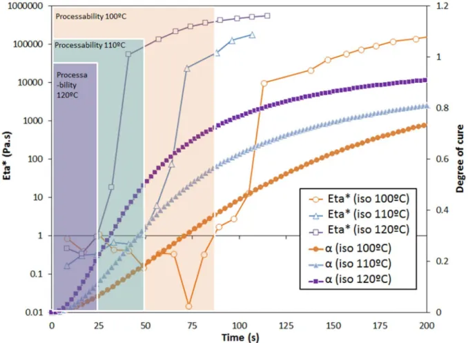
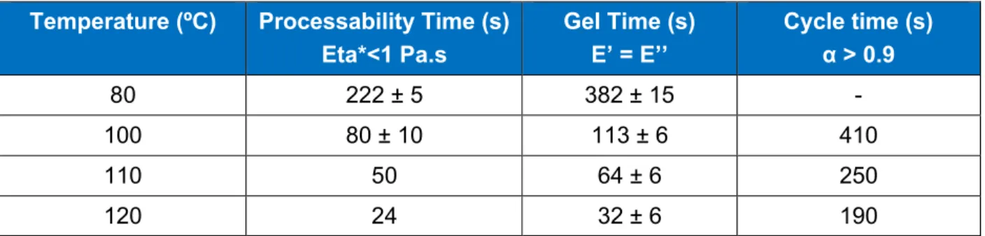
Figure 4 presents the resin reactivity at 100ºC, 110ºC and 120ºC. Both evolution of degree of cure and complex viscosity are plotted with time at the three isothermal temperatures. The processability time was defined as the time range when the viscosity remained below 1 Pa.s to allow the resin flow within the dry reinforcement. This time is shorter than the gel time determined with the rheology tests, at the intersection of the storage modulus E’ and the loss modulus E’’. The measured processability time and gel time are reported in Table 1. On the other hand, the evolution of degree of cure indicates the time needed for the resin to cure and retain enough strength for the composite part to be demoulded. It was assumed that at a degree of cure of 0.9, the composite part could be demoulded. Processing time to reach a degree of cure of 0.9 as a function of the temperature is also reported in Table 1. From these data, a processing temperature of 110ºC was selected, in order to allow enough time for the resin to flow and impregnate the dry reinforcement (50 s), while curing in less than 5 minutes.
Figure 4: Cure kinetics and rheology behaviour of the EPIKOTETMresin 05475 and EPIKURETMcuring agent 05500 under isothermal conditions (100ºC, 110ºC and 120ºC).
Table 1: Processing times for the EPIKOTETMresin 05475 and EPIKURETMcuring agent 05500 under isothermal conditions (80ºC, 100ºC, 110ºC and 120ºC)
Temperature (ºC) Processability Time (s) Eta*<1 Pa.s Gel Time (s) E’ = E’’ Cycle time (s) α > 0.9 80 222 ± 5 382 ± 15 -100 80 ± 10 113 ± 6 410 110 50 64 ± 6 250 120 24 32 ± 6 190 SNAP RTM moulding
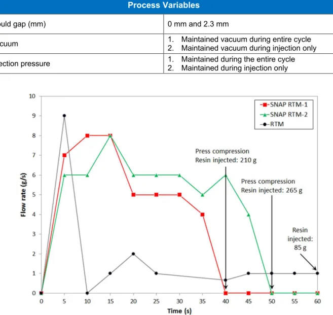
Table 2 summarizes the process conditions used for the moulding trials. RTM trials correspond to a moulding process with a fully closed tool (mould gap = 0 mm), while SNAP RTM trials correspond to a moulding process with a tool opened to a desired gap (mould gap = 2.3 mm). Cycle time was set to 5 minutes from the injection to the part demoulding. Injection time varied between 40 to 50 seconds. Resin flow rate was recorded and plotted in Figure 5. From this figure, it can be noticed that in the first 5 seconds, the resin flow rate is the same for both processes. However, after 5 seconds, a significant decrease in flow rate can be noticed for RTM trials. For the SNAP RTM process, the flow rate remains fairly high (5 – 6 g/s) during the injection step, until the press closure. The press was closed manually once the required amount of resin was injected into the part (approx. 200g). The press closure was also timed with the resin processability determined at 110ºC and before the resin gel time, so that the resin can still flow into the reinforcement after the compression to fill the remaining dry areas. Figure 6 shows the moulded plaque made with the EPIKOTETM05475/EPIKURETM05500 rapid cure resin and carbon
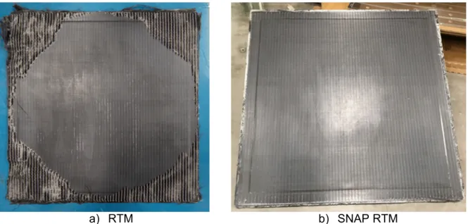
fibre reinforcement by RTM process and SNAP RTM process. The limited resin flow rate and the high resin reactivity led to a short filled plaque with the RTM process, while a fully impregnated plaque was obtained using the SNAP RTM process. The balanced and symmetrical 10 layer preforms exhibited no warpage when demoulded hot. Using the reinforcement mass, the resin mass and the density of the constituents, a fibre volume fraction of 56% was determined for the SNAP RTM plaques.
Table 2: Process moulding conditions
Process conditions
Resin EPIKOTEagent 05500, ratio 100:17TMresin 05475 and EPIKURETMcuring
Reinforcement ZoltekTM PX35 (0/90) MD 300 carbon fabrics
Layup [(0/90)]5s
Mould temperature Top : 110ºCBottom : 105ºC
Press pressure 100 tons
Process Variables
Mould gap (mm) 0 mm and 2.3 mm
Vacuum 1. Maintained vacuum during entire cycle2. Maintained vacuum during injection only
Injection pressure 1. Maintained during the entire cycle2. Maintained during injection only
a) RTM b) SNAP RTM
Figure 6: Carbon fibre reinforced composite plaque made by a) RTM and b) SNAP RTM process Mechanical performance
Mechanical performance was evaluated on three plaques moulded with the different process variables reported in Table 3. The sequences of injection pressure and vacuum were evaluated to determine their influence on part filling, porosity and mechanical performance. The effect of the mass of resin injected into the mould was also evaluated to determine its relation with part filling and part impregnation.
Table 3: Process variables of the tested plaques
Part ID Injection Pressure Vacuum Mass of resin
injected A Maintained during the entire cycle Maintained during the entire cycle 200 g
B Maintained during injection only during injection onlyMaintained vacuum 200 g
C Maintained during injection only during injection onlyMaintained vacuum 250 g
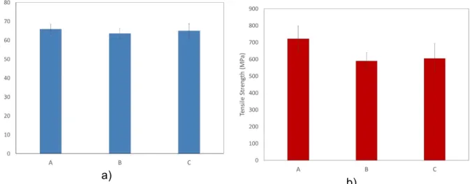
Figure 7, Figure 8 and Figure 9 present the tensile properties, flexural properties and glass transition temperature, respectively. Overall, excellent mechanical properties were measured. Higher tensile and flexural strength were measured for plaque A, when the injection pressure and the vacuum were maintained during the entire cycle. Maintaining the injection pressure and the vacuum during the entire cycle might have led to a better preform impregnation and a reduction of the porosities, resulting in higher tensile and flexural strength. However, from an economic stand point, this strategy would lead to processing cost increase. No difference in mechanical performance was measured between plaque B and C showing that there is no advantage in injecting more resin into the part, as long as a good impregnation level is reached. In this work, varying the vacuum cycles and injection pressure during moulding was carried out manually,
however, future work will involve automating these parameters, in order to achieve faster cycle times with improved mechanical results.
The glass transition temperature was measured at the onset of the decrease in storage modulus (E’) as recommended by ASTM D7028. Despite using the same process temperature and cycle time, a 10ºC difference in glass transition temperature was measured between plaque A (Tg= 108ºC) and plaques B and C (Tg= 119ºC).
a)
b)
Figure 7: Tensile modulus (a) and tensile strength (b) of carbon fibre reinforced composites moulded by SNAP RTM process
a) b)
Figure 8: Flexural modulus (a) and flexural strength (b) of carbon fibre reinforced composites moulded by SNAP RTM process
Figure 9: Glass transition temperatures of carbon fibre reinforced composites moulded by SNAP RTM process Part quality
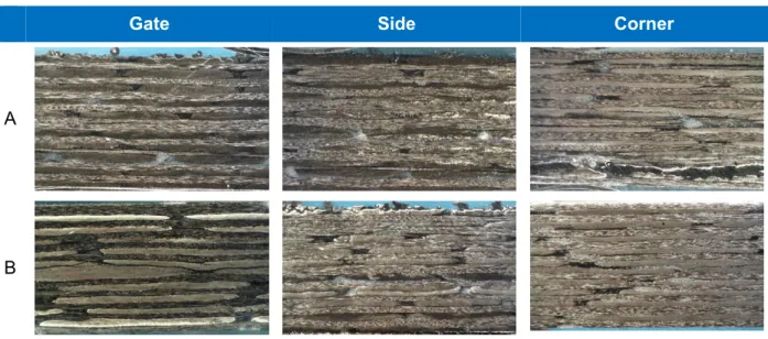
When observed visually, SNAP RTM plaques were fully filled with a good surface finish on both sides and having small impregnation defects in the pinch zone around the perimeter of the part. Minimal surface porosity was observed at the plaques. Three test samples were taken near the injection gate and on the plaques side and corners, for microscopic examination. The images, are shown in Table 4. They revealed good preform impregnation through the thickness with little porosity. There are some resin rich areas (darker zones), that can be observed between the carbon yarns. The impregnation quality is similar at each plaque location (gate, side and corner). No difference in impregnation quality or porosity content was observed between the three plaques. In some micrographs, a white filament can be observed around the yarn, which corresponds to the polyester threads used to knit together the biaxial non-crimp fabric.
Table 4: Plaque cross sections observed under optical microscope at 20X magnification
Gate Side Corner
A
C
Conclusion / Summary and next steps
In this paper, a low cost, low pressure injection equipment was used to manufactured high performance carbon fibre reinforced composite plaques with a 5-minute cycle time without automation. By investigating the resin processing properties (viscosity and cure kinetics) at various temperatures, a process temperature of 110 ºC was selected to achieve a cycle time under 5 minutes. The SNAP RTM parts had significantly improved quality over the standard RTM parts at significantly faster cycle times, with little porosity, no dry spots and a good impregnation of the dry reinforcement both at the surface and through thickness. Excellent mechanical properties were measured. The balanced and symmetrical 10 layer preforms exhibited no warpage when demoulded hot. Varying the vacuum cycles and injection pressure during moulding didn’t affect the impregnation quality and porosity content. Although, higher tensile and flexural strengths were measured when injection pressure and vacuum were maintained during the entire cycle.
The next steps of this project will focus on the automation of the process in order to have a more robust process with faster cycle times and improved quality and performance. The injection system and the press will be connected so that the press closure will automatically start once the required amount of resin is injected. Automated flushing and cleaning sequence of the mix head and the hydraulic valve will also be added to the process. Once demonstrated, the automated SNAP RTM process should enable the production of high performance composite parts under 5 minutes using a low cost low pressure RTM injection system.
Acknowledgements
The authors thank Chantal Coulombe, Normand Nardini and Mathieu St-Germain for their precious help for the tool design and part manufacturing. The authors also thank Patrick Gagnon and Manon Plourde for their help with mechanical testing.
References
1. S. Mazimdar, Opportunity and Challenges in Automotive Composites Industry, Lucintel Webinar, 2013
2. L. Cheah, Cars on Diet: The Material and Energy Impacts of Passenger Vehicle Weight Reduction in the U.S., Ph.D. Thesis, Massachusetts Institute of Technology, 2010
3. United State Environmental Protection Agency, Final rule for greenhouse gas emissions and fuel efficiency standards for medium and heavy duty engines and vehicles – Phase 2,
https://www.epa.gov/regulations-emissions-vehicles-and-engines/final-rule-greenhouse-gas-emissions-and-fuel-efficiency
2016
5. D. H. Bank, A. James, S. Belli, J. R. Reese, R. E. Baumer, B. Balijepalli, L. Ma, M. Reimers, R. Königer, T. Morley, L. Lotti, Composite technology for high volume lightweight manufacturing, In Press
6. M. Deleglise, P. Le Grognec, C. Binetruy, P. Krawczak, B. Claude, Modeling of high speed RTM injection with highly reactive resin with on-line mixing, Composites: Part A, 42, 2011
7. S. L. Agius, M. Joosten, B. Trippit, C. H. Wang, T. Hildtich, Rapidly cured epoxy/anhydride composites: Effect of residual stress on laminate shear strength, Composite: Part A, 90, 2016 8. M. W. Joosten, S. Agius, T. Hilditch, C. Wang, Effect of residual stress on the matrix fatigue