Publisher’s version / Version de l'éditeur:
Vous avez des questions? Nous pouvons vous aider. Pour communiquer directement avec un auteur, consultez la Questions? Contact the NRC Publications Archive team at
[email protected]. If you wish to email the authors directly, please see the first page of the publication for their contact information.
https://publications-cnrc.canada.ca/fra/droits
L’accès à ce site Web et l’utilisation de son contenu sont assujettis aux conditions présentées dans le site LISEZ CES CONDITIONS ATTENTIVEMENT AVANT D’UTILISER CE SITE WEB.
Technical Report (National Research Council of Canada. Ocean, Coastal and
River Engineering), 2013-12-01
READ THESE TERMS AND CONDITIONS CAREFULLY BEFORE USING THIS WEBSITE. https://nrc-publications.canada.ca/eng/copyright
NRC Publications Archive Record / Notice des Archives des publications du CNRC : https://nrc-publications.canada.ca/eng/view/object/?id=ab0629eb-db7c-4f2f-b8c6-02f71ff54ba7 https://publications-cnrc.canada.ca/fra/voir/objet/?id=ab0629eb-db7c-4f2f-b8c6-02f71ff54ba7
Archives des publications du CNRC
For the publisher’s version, please access the DOI link below./ Pour consulter la version de l’éditeur, utilisez le lien DOI ci-dessous.
https://doi.org/10.4224/40000429
Access and use of this website and the material on it are subject to the Terms and Conditions set forth at
Aids to navigation design and review: Phase I report
Kennedy, Allison; Raman-Nair, Wayne; Williams, Christopher; Seo, Dong
Cheol
OCRE-TR-2013-048
NATIONAL RESEARCH COUNCIL CANADA OCEAN, COASTAL AND RIVER ENGINEERING
Aids to Navigation Design and Review
Phase I Report
Technical Report
Allison Kennedy, Wayne Raman-Nair, Christopher Williams and Dong Cheol Seo December 2013
National Research Council Canada Ocean, Coastal and River Engineering Conseil national de recherches Canada Génie océanique, côtier et fluvial UNCLASSIFIED
Aids to Navigation Design and Review
Phase I Report
OCRE-TR-2013-048
Allison Kennedy, Wayne Raman-Nair, Christopher Williams and Dong Cheol Seo
This report summarizes the results of the work completed in Phase I of the CCG-funded project: Aids to Navigation Design and Review. In general, this project involves the devel-opment of a tool to help quantify navigational risk to support the design of marine short range navigational aid systems. Phase I of this project includes a review of currently avail-able guidelines and tools for the design of navigational aid systems and waterways, as well as the preliminary development of the Navigational Risk Identification Module (NRIM).
Content and Structure
Section 1 introduces this investigation and describes its main elements. Section 2 provides a review of existing guidelines and tools that support the design and review of marine navi-gational aid systems. Section 3 outlines the preliminary development of the NRIM in terms of an assessment of methods to predict squat, a review of wave induced heave and pitch prediction as well as details of maneuvering model development. Section 4 outlines the vessel and channel parameters used in Phase I of this investigation. Section 5 presents preliminary comparisons of Phase I NRIM output with the outputs from the Kitimat study; this includes ship zig-zag and turning circle performance, effects of wind, waves and shal-low water, squat and heave and pitch predictions, and, a discussion of the discrepancies found. Section 6 outlines the work proposed for Phase II including narrow-channel and bank-proximity effects, two-way traffic, overtaking and passing effects. Section 6.6 sum-marizes questions posed for the work of Phase II. Appendix A provides the details for the ship maneuvering model and explains how the trajectory of the ship is simulated. Ap-pendix B provides the details for how the wave-induced motions of ships are estimated; examples are provided for a VLCC including comparisons with the outputs of the Kitimat study. Appendix C provides the details for how ship squat is predicted by 16 different for-mulae for open-water conditions, and, by seven forfor-mulae for confined-waterway conditions; comparisons are made with limited full-scale measurements in the Panama Canal.
Conclusions
During this preliminary investigation there were a number of potential methods explored that predict ship hydrodynamic derivatives (required by the maneuvering model), ship squat and wave induced motions. The Phase I review was not exhaustive since there were a large number of formulations available in the literature, that could be used to predict the aforementioned parameters. Based on those that were reviewed, certain methods did demonstrate more promising attributes than others in terms of their usefulness in NRIM for the open water case. For hydrodynamic derivative prediction, the empirical equations pre-sented by Clarke [1], when used in the Phase I maneuvering model, compared reasonably well to the simulated data provided in the Kitimat study. Another positive attribute of these equations is that they have shallow water correction factors available. In terms of wave induced motions, the predictions using the empirical formulation by Jensen [2] followed the trend of predictions with the strip-theory method and provide a relatively un-complex and
analytical equation for prediction. The strip-theory method provides a more accurate pre-diction by considering the detailed geometry of hull form and compares well to ShipMo3D predictions. The assessment of ship squat, as detailed in Appendix C, considered a num-ber of empirical relationships, some of which correlated closely with measured data. A positive attribute of all of the aforementioned formulations is that they require only basic (non-complex) input relating to the ship or channel. In addition, the use of such meth-ods would require minimal computation time and would not require expertise for problem set-up. This type of formulation may be better suited to the problem at hand as opposed to complex methods which require difficult input and lengthy computational time. Valida-tion of these methods against full or model scale data would allow for a more thorough assessment of their performance.
Contents
List of Figures . . . . v
List of Tables . . . . vii
List of Acronyms . . . . viii
1 INTRODUCTION . . . . 1
2 REVIEW OF EXISTING LITERATURE AND TOOLS . . . . 3
2.1 Design Guidelines . . . 3
2.1.1 CCG Guidelines . . . 3
2.1.2 PIANC Guidelines . . . 5
2.2 Design Tools . . . 7
2.2.1 Japan Fairway (2010) . . . 7
2.2.2 SimFlex Navigator (FORCE Technology) . . . 12
3 PHASE I NRIM DEVELOPMENT . . . . 14
3.1 Minimum Depth Allowance . . . 14
3.1.1 Squat Assessment Details . . . 14
3.1.2 Wave-induced Heave and Pitch Consideration . . . 14
3.2 Maneuvering Model . . . 16
3.2.1 Maneuvering Model Literature Review . . . 16
3.2.2 Phase I Maneuvering Model Description and Details . . . 18
3.2.3 Maneuvering Model Output and Performance . . . 19
3.3 Decision on Shallow and Open Water . . . 19
4 PHASE I SCENARIO DETAILS . . . . 21
4.1 Vessel Details . . . 21
4.2 Channel Geometry . . . 22
5 PHASE I NRIM OUTPUT . . . . 24
5.1 Comparison with Kitimat Study . . . 24
5.1.1 Maneuvering Performance . . . 24
5.1.2 Squat Comparisons . . . 35
5.1.3 Heave and Pitch Comparisons . . . 35
5.2 Additional Considerations for CCG Required Output . . . 38
5.2.1 Minimum Depth Allowance . . . 38
5.2.2 Minimum Channel Width . . . 41
5.2.3 Radius of Turn, Advance and Transfer . . . 42
OCRE-TR-2013-048 Contents
6 PHASE II DEVELOPMENT . . . . 44
6.1 Narrow Channel Maneuvering - Bank Effect . . . 44
6.2 Two Way Traffic, Overtaking Vessels and Passing Vessels . . . 45
6.3 Implementation of Other Vessels . . . 46
6.4 Probabilistic Capabilities . . . 47
6.5 Development of GUI . . . 48
6.6 Questions for Working Group . . . 49
References . . . . 52
Appendices . . . . 57
A MANEUVERING MODEL . . . . 58
A.1 Governing Equations . . . 58
A.2 MMG Model . . . 59
A.3 Forces on Hull in Calm Water . . . 60
A.4 Forces on Rudder . . . 61
A.5 Forces due to Current and Wind . . . 62
A.6 Thruster Forces . . . 63
A.7 Dimensionless Form of Governing Equations . . . 63
A.8 Trajectory Simulation . . . 64
B WAVE-INDUCED MOTION . . . . 66
B.1 Introduction . . . 66
B.2 Empirical Method for Wave-induced Motion . . . 66
B.2.1 Fairway Standard of Japan . . . 66
B.2.2 Jensen (2004) . . . 68
B.2.3 IACS JTP . . . 69
B.3 Theoretical Background . . . 70
B.3.1 Equation of Motion . . . 70
B.3.2 Strip Method . . . 72
B.3.3 2D Added Mass and Radiation Damping . . . 74
B.3.4 2D Diffraction Force . . . 76
B.3.5 Wave-induced Motion . . . 77
B.4 Summary of Wave-induced Motion Prediction Software . . . 77
B.4.1 Software Package Summary . . . 77
B.4.2 Analysis Input . . . 77
B.4.3 Analysis Output . . . 80
B.5 Analysis Result . . . 84
B.5.1 Added Mass and Damping of Barge . . . 84
B.5.2 Wave-induced Motion of Generic VLCC . . . 85
B.5.3 Comparison with Kitimat study . . . 85
B.6 Discussion and Summary . . . 92
C SHIP SQUAT . . . . 93
C.1 Purpose . . . 93
C.2 Introduction . . . 93
C.3 Background, Definitions, Diagrams etc. . . 94
C.3.1 A ship in unrestricted uniform-depth shallow water . . . 96
C.3.2 A ship in a confined waterway . . . 98
C.4 Some Formulae for Predicting Squat in Unrestricted Uniform-depth Shallow Water . . . 103
C.4.1 Tothill 1966 . . . 104
C.4.2 Tuck 1966 . . . 104
C.4.3 Hooft 1974 . . . 105
C.4.4 Huuska and Guliev 1976 . . . 105
C.4.5 Eryuzlu and Hausser 1978 . . . 105
C.4.6 ICORELS 1980 . . . 105 C.4.7 Norrbin 1986 . . . 105 C.4.8 Römisch 1989 . . . 106 C.4.9 Millward 1990 . . . 107 C.4.10 Millward 1992 . . . 107 C.4.11 Eryuzlu et al 1994 . . . 107 C.4.12 Yoshimura 2002 . . . 107 C.4.13 Barrass 1979, 1981 . . . 107 C.4.14 Barrass 2004 . . . 108 C.4.15 Barrass 2006 . . . 108 C.4.16 Barrass 2009 . . . 109 C.4.17 Ankudinov 2009 . . . 109
C.5 Examples for an Unrestricted Waterway . . . 112
C.5.1 Effects of H/T on the squat predictions for a VLCC . . . 112
C.5.2 Consideration of the TERMPOL report squat predictions for a VLCC 118 C.6 Formulae for Trapezoidal Canals . . . 120
C.6.1 Huuska and Guliev 1976 . . . 121
C.6.2 Eryuzlu et al 1994 . . . 121 C.6.3 Römisch 1989 . . . 122 C.6.4 Barrass 2006 . . . 122 C.6.5 Barrass 2009 . . . 122 C.6.6 Ankudinov 2009 . . . 123 C.6.7 Yoshimura 2009 . . . 123
C.7 Examples for Trapezoidal Canals . . . 124
C.8 Formulae for Trenched Channels . . . 135
C.8.1 Römisch 1989 . . . 135
OCRE-TR-2013-048 Contents
C.8.3 Barrass 2009 . . . 137
C.8.4 Ankudinov 2009 . . . 137
C.8.5 Yoshimura 2009 . . . 137
C.8.6 Huuska and Guliev 1976 . . . 137
C.9 Examples for Trenched Channels . . . 139
C.10 Sensitivity Analyses . . . 140
C.11 Other Verifications . . . 144
C.12 Regression Analysis . . . 148
C.13 Observations, Cautions, Conclusions . . . 148
List of Figures
1 Kimimat Study Zig-Zag Maneuver (Adapted from FORCE Technology [3]) . 25
2 NRIM Zig-Zag Maneuver . . . 25
3 Turning Circle 1 - Engine at Full Power . . . 27
4 Turning Circle 2 - Engine Setting for 10 knots Forward Speed . . . 28
5 Effect of Wind Maneuver . . . 30
6 Turning Circle in Shallow Water . . . 32
7 Hull Shape of Generic VLCC for Comparative Study . . . 36
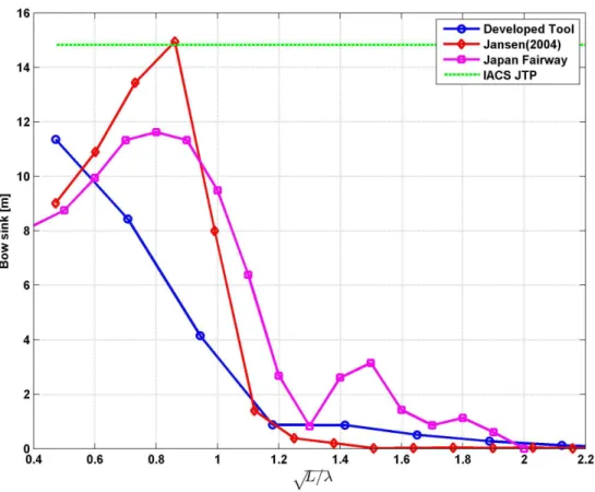
8 Bow Sink in15m of Significant Wave Heights with Quatering Sea, 130◦ (L: Ship Length,λ : Wave Length ) . . . 37
9 Minimum Depth Allowance . . . 39
A.1 Configuration . . . 58
A.2 Rudder Forces . . . 61
B.1 Ratio of Heave Motion and Wave Amplitude: 10 Sections Regarding VLCC, VLCC Study Group . . . 67
B.2 Coordinate System and Relative Wave Heading . . . 71
B.3 2D Hull Section and Boundaries . . . 75
B.4 Work Flow of Developed Strip Method Tool . . . 78
B.5 Typical Result of Bow Sink Amplification Factor . . . 80
B.6 Typical Result of Heave and Pitch RAO . . . 81
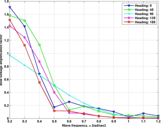
B.7 Bow Sink Amplification Factor for Various Wave Headings with 10 knot of Forward Speed . . . 82
B.8 Typical boundary condition from MATLAB script of BEM2D.m, BEM2D . . . 83
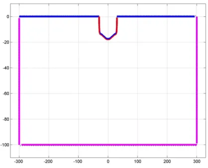
B.9 Typical 3D hull model from MATLAB script of offsetReader.m . . . 83
B.10 Added Mass and Radiation Damping Coefficient for Barge . . . 84
B.11 Ratio Between Bow Sink and Wave Amplitude with Head sea . . . 86
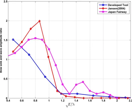
B.12 Ratio Between Bow Sink and Wave Amplitude with Quatering sea, 130◦ . . 87
B.13 Bow Sink in 15 m of Significant Wave Height with Head Sea . . . 88
B.14 Bow Sink in 15 m of Significant Wave Heights with Quartering sea, 130◦ . 89 B.15 Bow Sink Amplification Factor in Various Depths with 135◦of Wave Heading 90 C.1 Bow wave, water-surface drawdown and stern wave in unrestricted and shal-low water; the ship is travelling from left to right. . . 95
C.2 Transfennica showing bow wave, water-surface drawdown and stern wave produced at 20 kt with 10 m under-keel clearance. . . 95
C.3 Unrestricted uniform-depth shallow water . . . 96
C.4 A ship in unrestricted uniform-depth shallow water . . . 97
C.5 A trapezoidal channel . . . 98
C.6 Channel with trench of trapezoidal cross-section . . . 99
C.7 Channel with trapezoidal cross-section and trapezoidal trench . . . 99
C.8 A rectangular channel or lock . . . 99
OCRE-TR-2013-048 List of Figures
C.10 A rectangular channel with a ship,Am andAwdefined . . . 100
C.11 Definition of drawdown and squat . . . 102
C.12 Definition diagram for ship particulars . . . 102
C.13 Results for a VLCC in open water for water-depth to draft ratio 1.10 . . . 113
C.14 Results for a VLCC in open water for water-depth to draft ratio 1.20 . . . 114
C.15 Results for a VLCC in open water for water-depth to draft ratio 1.30 . . . 115
C.16 Results for a VLCC in open water for water-depth to draft ratio 1.40 . . . 116
C.17 Results for a VLCC in open water for water-depth to draft ratio 1.50 . . . 117
C.18 Bow squat versus ship speed for severalWef f values for a VLCC in open-water conditions with H/T of 1.30 . . . 118
C.19 Elbe tanker, bow squat measurements and predictions, Panama Canal . . . 128
C.20 Global Challenger bulk carrier, bow squat measurements and predictions, Panama Canal . . . 129
C.21 Majestic Maersk container ship, stern squat measurements and predictions, Panama Canal . . . 130
C.22 OOCL Fair container ship, stern squat measurements and predictions, Panama Canal . . . 131
C.23 Elbe tanker, bow squat measurements and average of six predictions, Panama Canal . . . 132
C.24 Global Challenger bulk carrier, bow squat measurements and average of six predictions, Panama Canal . . . 133
C.25 Majestic Maersk container ship, stern squat measurements and average of three predictions, Panama Canal . . . 134
C.26 OOCL Fair container ship, stern squat measurements and average of three predictions, Panama Canal . . . 135
C.27 Curves ofK1 versus blockage ratioS for trenched channels for the Huuska-Guliev formula . . . 139
C.28 Elbe tanker, Barrass squat sensitivity based on variations in parameters of a trapezoidal canal . . . 141
C.29 Elbe tanker, squat measurements and range of Barrass predictions based on variations in parameters of a trapezoidal canal . . . 143
C.30 Predictions for VLCC bow squat for various values of the river width of influ-enceWef f . . . 144
C.31 Predictions for VLCC stern squat for various values of the river width of influenceWef f . . . 145
C.32 Predictions for VLCC trim angle for various values of the river width of influ-enceWef f . . . 146
C.33 Predictions for VLCC bow squat for various values of speed and river width of influenceWef f . . . 147
List of Tables
1 Assessment of Japanse Tool . . . 11
2 Comparison Table between Empirical Methods of Wave-induced Motion . . 15
3 Example of Strip Method Calculation Time . . . 16
4 Phase I Vessel Particulars - VLCC 3219 . . . 22
5 Phase I Channel Details . . . 22
6 Estimated Parameters in NRIM Phase I Output . . . 34
7 General Specification of Generic VLCC . . . 35
8 MDA Parameters and Characteristics . . . 39
B.1 Wave-induced Motion Prediction Software Package Content . . . 77
B.2 Input Data for Wave-induced Motion Prediction . . . 79
B.3 Test Barge Dimensions . . . 84
B.4 General Specification of Generic VLCC . . . 85
B.5 Environmental Condition . . . 85
B.6 Additional Assumptions for IACS JTP Rule . . . 88
B.7 Wave Condition of Coastal Areas in Kitimat Study . . . 89
C.1 Parameters for Ship Squat Predictions in Unrestricted Shallow Waterways . 97 C.2 Capabilites of various ship squat formulae for unrestricted (U), restricted (R) and canal (C) waterways . . . 103
C.3 Constraints on Parameters for Various Squat Formulae . . . 104
C.4 Particulars for the four ships in the Panama Canal measurements . . . 124
C.5 Goodness of fit for squat predictors to DGPS measurements, Panama Canal 126 C.6 Values of curve-fit coefficients for Huuska and GulievK1(S) . . . 139
C.7 Mean and standard deviation forCb for a large number of ships of eight types 148 C.8 Typical Coefficients of Form for Various Types of Ships . . . 150
OCRE-TR-2013-048 List of Acronyms
List of Acronyms
AMCSD Analysis Module of Climatological Site Data BEM Boundary Element Method
CCG Canadian Coast Guard
CFD Computational Fluid Dynamics DOF degree of freedom
DOFs degrees of freedom
DRDC Defence Research and Development Canada DGPS Differential Global Positioning System
GPS Global Positioning System GUI Graphical User Interface
IACS International Association of Classification Society JTP Joint Tanker Project
LCG Longitudinal Centre of Gravity MDA Minimum Depth Allowance MMG Mathematical Modelling Group NRC National Research Council Canada NRIM Navigational Risk Identification Module
OCRE Ocean, Coastal and River Engineering portfolio OEB Ocean Engineering Basin
PIANC Permanent International Association of Navigation Congresses PMM Planar Motion Mechanism
RAO Response Amplitude Operator VLCC Very Large Crude Carrier
1
INTRODUCTION
This report provides details Phase I of a project, undertaken by the National Research Council Canada (NRC) of Canada, that aims to develop a numerical tool to support the Canadian Coast Guard (CCG) process for the design and review of marine Aids to Navi-gation systems. The first component of Phase I involved a review of existing design guide-lines and support tools. A comprehensive review of the CCG Procedures Manual for the design and review of marine short-range aids to navigation systems as well as the water-way design guidelines developed by PIANC was completed. This was complemented by a detailed review of two numerical tools that could provide design support. The first, a tool developed primarily by the Japan Institute of Navigation, was identified by the CCG during initial project discussions. The second was a tool developed by FORCE Technology which is the source of the simulated data that was provided to NRC by the CCG for comparison and validation of Phase I work.
The second component of Phase I involves the preliminary development of a numerical tool, labelled as the Navigational Risk Identification Module (NRIM), to support the CCG Navigational Aid System design and review process. The NRIM is designed to provide output as specified by CCG. The development of NRIM is supported by findings from the review of existing guidelines and potential support tools. The NRIM is comprised of two main components: the Minimum Depth Allowance (MDA) model and the maneuvering model. Each component is developed independently and reported separately in this doc-ument. The description of NRIM development includes a discussion of preliminary NRIM capabilities, required input and assumptions.
The third component of Phase I involves providing the output from preliminary NRIM and maneuvering model for a specified scenario. The NRIM output is compared to simulated data provided by the CCG. Details of these comparisons are provided as well as a dis-cussion of possible justifications for discrepancies. Subsequently, details of the CCG re-quested NRIM output are discussed in relation to the Phase I output. In some instances, the Phase I NRIM output provides only a component of a requested parameter. For exam-ple, preliminary NRIM can output squat, heave and pitch motions, which are considered in the computation of MDA. However, preliminary NRIM does not consider any safety fac-tor that may be applied to the MDA calculation. In these cases, potential additions to the Phase I NRIM output are described to allow for full investigation of the parameters.
The final section of this report includes a summary of details relating to proposed Phase II NRIM development. Phase II development was summarized in the project proposal and designed to achieve the desired NRIM output as requested by CCG. Through Phase I development, findings and insight relating to the tasks involved in Phase II have been iden-tified and are summarized for consideration. The details provided in this report should lead group discussions between the CCG working group and NRC project team, to effectively
OCRE-TR-2013-048 1 INTRODUCTION
2
REVIEW OF EXISTING LITERATURE AND TOOLS
A review of select design guidelines and tools was conducted during Phase I. This review allowed for the investigation of areas of the navigational aid system design and review which MDA could support and the identification of empirical relations and computational methods that could support the development of NRIM.
2.1 Design Guidelines
There were two design guidelines reviewed in detail during Phase I. The first was the CCG guidelines for design and review of marine navigational aid systems [4]. The second was PIANC guidelines for the design of ports and channels [5]. The review of these guide-lines resulted in a better understanding of current means to assess navigational threat and identify areas that NRIM could support.
2.1.1 CCG Guidelines
The CCG Procedures Manual for Design and Review of Short-Range Marine Aids to Nav-igation, referred to hereafter as CCG Guidelines, describe the procedure of design and review in four distinct steps, which include: 1. basic site review, 2. preliminary hazard iden-tification and threat rating, 3. needs analysis, 4. operational analysis. The basic site review involves the collection of data relevant to the site including historical environmental data, bathymetry, existing navigational aids and types of vessels that use the site. Data collected from step one is consolidated on the site data sheet and the procedures for data collec-tion are summarized in Chapter 2 of the CCG Guidelines. Step two, the preliminary hazard identification and threat rating, involves the assessment of an initial rating on the severity of each threat. The results of the preliminary rating of each unique threat are summarized on the preliminary threat rating sheet and the procedures for assessing the preliminary threat rating are reviewed in Section 3 of the CCG Guidelines. The needs analysis, step three, involves the rating of composite threats, identifying generic types of navigational aids to reduce these threats, and assessing how the potential and currently existing navigational aids reduce threats. The procedures for the needs analysis are summarized in Chapter 4 of the CCG Guidelines and the results of the assessment are compiled in the needs matrix. The final step, operational analysis, involves conducting an operational based assessment of site-specific requirements to compliment the results of the previous steps. This step is completed separately for open and confined waters and the procedures are summarized in Chapter 5 and Chapter 6 of the CCG Guidelines, respectively. The operational analysis involves consultations with waterway users by which any questions arising from the previ-ous steps can be confirmed.
In general, NRIM can support the processes involved in step numbers two and three. In terms of the preliminary threat rating, step two, NRIM will allow for the direct assessment
OCRE-TR-2013-048 2 REVIEW OF EXISTING LITERATURE AND TOOLS
and quantification of benchmark values to represent the threat ratings for many of the threats outlined on the preliminary threat rating sheet. The specific benchmark values that NRIM can assist in quantifying include: non-threatening under keel clearance value and the “significant” and “highly significant” limits representing the distance from other ves-sel when passing, minimum channel width, angle of turn in channel, wind speed, current speed along track and current speed across track. Currently these benchmark values are provided on the generic preliminary threat rating form and change for the different ranges of vessel length, beam, draft and gross tonnage considered. These benchmark values resulted from consultation with experienced navigators.
To exemplify the use of MDA to assess and quantify the preliminary threat rating bench-mark values, let’s consider the non-threatening under keel clearance benchbench-mark. This benchmark ranges between 3m and 15 m, pending on the basic vessel particulars. To as-sess this value for a particular vessel category, NRIM could be used to simulate the MDA using a wide range of vessel speeds and environmental conditions. This would give an idea of how the MDA varies with different environmental conditions and vessel speeds and indicate the maximum MDA requirement. The MDA requirement calculated using NRIM includes the vessel draft, squat and wave induced heave and pitch (at this stage). The MDA calculation includes additional consideration than the calculation used in the CCG Guideline which includes only vessel draft, maximum wave height and the safety factor (non-threatening under keel clearance benchmark). Since the MDA computation is a more thorough computation involving coupled effects of environmental and vessel parameters, it would result in less uncertainty and may result in a decision for a lower safety factor value. The safety factor could be selected by adding a percentage of the maximum MDA computed by NRIM.
The support that NRIM could provide step number three, the needs analysis, relates to defining the composite threat rating. This support is both indirect and direct. Indirectly, the composite threat analysis makes use of the preliminary threat ratings in the assessment. As described in the previous paragraphs, NRIM can be used to assess the preliminary threat rating benchmarks and therefore have an impact on the composite threat rating. Another way that NRIM would support step three is by considering the environmental con-ditions that are unique to the given waterway and using them to help define the threats specific to the site. NRIM could be used to simulate specific maneuvers through a defined section of the waterway to determine the performance in different environmental condi-tions. In terms of the composite threats highlighted on the needs matrix form, NRIM could directly support rating of: sea conditions, proximity of hazards, complexity of track, and diminished room to maneuver.
In general, NRIM can be used as a numerical design tool to complement the use of CCG guidelines for the design and review of marine short range aids to navigation systems. By doing this, the overall design and review process becomes less prescriptive. The use of
NRIM will allow for the design of a navigational system that is uniquely tailored to a given waterway, set of environmental conditions, and vessels. This type of design is impossible using only a set of prescriptive based regulations. A performance based approach will help reduce the risk of over designing a navigational aid system which could lead to reduced costs for the CCG.
Besides those mentioned above, there are other areas of the design and review process that NRIM could support, such as the selection of type of navigational aid and positioning of the aids. This would have to be examined further and would involve the implementation of empirical relations involving the detection of drift, such as those used in the Japanese Tool (Japanese Port Authority). These equations only examine detection of drift through floating buoys, an anchored lit spar, or through GPS or DGPS. Therefore, implementation of these, or similar equations would only support the selection, design and positioning of drifting buoys and an anchored spar, other navigational aids would not be considered. There could be other empirical relations existing in the literature that consider other types of navigational aids. The investigation of this type of equation, and integration into NRIM is beyond the scope of the current project. However, this could be investigated in the future based on CCG recommendation.
2.1.2 PIANC Guidelines
The Permanent International Association of Navigation Congresses (PIANC) in coordi-nation with the Intercoordi-national Association of Ports and Harbours, has developed a set of guidelines to support the design of channels and ports. The guideline, entitled “Approach Channels: A Guide for Design,” was published in June, 1997 [5]. An updated version of this document is under preparation by PIANC and was expected for publication in the first or second quarter of 2012 (PIANC Presentation [6]). The updated publication could not be located through a literature search and may have a delayed release date. These updates could not be obtained for inclusion in this review. The PIANC guidelines involve the de-sign of a channel or port as opposed to dede-sign of navigational aid system. However, the general guidelines in terms of identification of navigational hazards are common to both processes. In addition, the PIANC guidelines focus on ports and channels as opposed to general waterways. The methodology for waterway design in PIANC involves an initial concept design supplemented later with a detailed design. The concept design makes use of generic guidelines based on experimental results and operational guidance from ves-sel navigators. The detailed design makes use of computer based design tools such as programs to simulate vessel maneuvering and identify and quantify risk.
Support for Navigational Aid System Design
The PIANC guidelines contain insight that could be used to support the CCG design and review of marine aids to navigation procedures. Two key areas of support are described
OCRE-TR-2013-048 2 REVIEW OF EXISTING LITERATURE AND TOOLS
below. In short, the first area of support relates to using the generic guidance summarized in PIANC, to make a preliminary threat rating for scenarios in which there is limited data. This could be incorporated into NRIM in the future if this is of interest to CCG. The second area of support relates to integrating some of the listed empirical formula into NRIM to allow for consideration of different scenarios.
To elaborate on the first area of support, the PIANC guidelines also provide generic guid-ance on certain aspects of the design. For example, for concept design concerning the minimum depth allowance the guideline indicates that a depth to draft ratio of 1.10 is com-monly used across the globe as a minimum. This includes a safety margin and is related to calm sea conditions. A value of 1.3 is indicated for channels with wave action. Similarly, the guidelines indicate that a vessel turning radius in calm water will be in the range of one to two times the vessel length in deep water. In shallow water, the turning radius is indicted to be approximately 5 or more times the vessel length. These details arise from the result of a study involving a single screw/single rudder container ship operating in dif-ferent water depths. These types of generic values could be used by CCG to enable a conservative threat rating for scenarios in which little to no data is available relating to the vessel particulars or environmental conditions. The preliminary NRIM requires the input of data relating to the environment, vessel particulars and channel geometry to allow for investigation of threat for a given scenario. In cases where this information is not available, it may be appropriate to use generic guidelines to obtain a preliminary threat rating. This type of general guidance could be integrated into NRIM so that it could be selected to pro-vide guidance for scenarios with limited data.
The PIANC guidelines provide relatively simple formulations for the calculation of certain parameters such as the required bank clearance. Currently NRIM is not equipped with formula to compute bank loads and thus it cannot predict the effects of a bank on ma-neuvering. This will be considered in Phase II in terms of a review of empirical relations to compute bank loading that are existing in the literature. The generic PIANC guidance relating to vessel speed and environmental conditions could be added as an alternative to allow for calculation of a conservative guideline. In addition, general guidance is provided to assess additional maneuvering lane requirements for different channel bottom types: smooth and soft, smooth and hard and rough and hard. This insight could be incorporated into NRIM during Phase II as a conservative measure since a detailed investigation of this effect was not proposed for consideration.
Another area of support from the PIANC guidelines relates to the examination of threat benchmark values. There is some operational guidance provided in PIANC that could help to define the vessel settings to use when assessing the threat benchmarks for select parameters. The threat benchmarks are the values that denote a significant or highly significant threat, and can be examined using NRIM. For example, NRIM can be used to investigate the turning performance of a vessel in a given channel parameter, but cannot
define what constitutes a significant threat. It is obvious that if the vessel turn is larger than the available channel turning radius at certain environmental conditions, then this is a significant threat. However, what constitutes a moderate threat may be harder to define. The PIANC guidelines indicate that a turn should never be designed for 100% rudder angle as this leaves no reserve for correction against environmental forces. Instead, the guidelines reference operational guidance from ship-handlers that indicate a comfort zone when turning at rudder angle between 15 and 20% of the maximum rudder angle. Therefore, for waterways in which there are turns that require a larger rudder angle, this may relate to a threat.
2.2 Design Tools
There were two design tools investigated in detail during Phase I. The first is the Japanese Fairway tool which provides select output in support of the design of a channel or waterway. The second is the FORCE Technology simulator which can assess fast time maneuvering scenarios and output the trajectories indicating vessel performance. This review is aimed to identify any components of the existing tools that could be used to support NRIM devel-opment.
2.2.1 Japan Fairway (2010)
A review of the Japanese tool [7] was conducted to investigate three key items: the basic output of the tool, how the basic output is calculated, the overall capabilities of the tool, and how the tool compares to CCG desired output as well as NRIM Phase I.
Basic Output of Japanese Tool & Details of Methodology
The Japanese has three output parameters which include: the MDA, the minimum channel width and the radius of turning circle. Details of the methodology and equations used to calculate these parameters are provided below.
Calculation of MDA
The MDA is calculated by adding together the vessel draft, squat, the maximum of heave plus pitch (bow sink) or heave plus roll (bilge keel sink) and a parameter referred to as the “allowance of depth.”
MDA = d + Squat + Max(heave + pitch, heave + roll) + allowance of depth
The parameter d is the maximum vessel draft in still water. The allowance of depth ac-commodates for the list of a vessel due to a large rudder angle to alter the course. This parameter is calculated based on a simple relation to the vessel draft. For vessel drafts less than or equal to 10 m the allowance of depth is set to 0.5 m and for larger vessel
OCRE-TR-2013-048 2 REVIEW OF EXISTING LITERATURE AND TOOLS
drafts it is set to 0.05 multiplied by the draft. There is no reference provided as to where this relationship originated.
For: d≤ 10 m; allowance of depth = 0.5 m d> 10 m; allowance of depth = 0.05 · d
The squat is calculated using a single equation that was formulated by Yoshimura, 1986 [8]. This equation is used to estimate the vessel squat for all scenarios considered. The refer-ence for this squat formulation was provided but the paper was only available in Japanese. Therefore, details relating to the data from which this squat formula was derived is still unknown. If the equation was derived using model scale tests of one specific hull form or channel configuration it may introduce error when used to predict the squat for scenar-ios that greatly differ from this case. The squat formula is a function of the vessel draft, waterway depth, vessel length, breadth and speed as well as the block coefficient. The calculation does not consider the width of the waterway and it is uncertain if it was defined for open or narrow waterways.
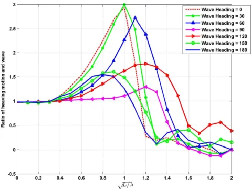
The bow sink due to heave and pitch (heave + pitch) is estimated using a plot of the ratio of heave to wave amplitude versus a function of vessel length. Documentation indicates that this graphic was defined by the Very Large Crude Carrier (VLCC) study group. No further detail on this reference is provided. The data presented on the graphic is based on a block coefficient of 0.7, Froude number of 0.1 and deep water.
The bilge sink due to heave and roll (heave + roll) is estimated using an empirical equation by Honda, 1998 [9]. This parameter is only considered when the natural rolling period is nearly equal to the meeting period between the vessel and wave. In all other conditions it is assumed that the bow sink is larger than the bilge sink. The Honda equation is a function of the significant wave height, vessel breadth and maximum vessel rolling angle.
In the Japanese tool, there is no additional depth allowance added to account for different vessel bottom shape, such as a flat or round bottom. When predicting the bilge keel sink due to wave-induced motion, the flat bottom is applied resulting in a conservative result. Moreover, the Japanese tool does not add a component to the MDA to account for vessel heeling due to course change or maneuvering effects.
In the Spanish ROM guidelines, section 7.2.3.8, which is not reviewed in this report, a factor to account for the heeling effect during turning is described. The theoretical background behind this factor relates to the balance between centrifugal force and restoring force. However, the calculation of this factor requires many parameters including: turning radius, speed, centre of gravity, centre of buoyancy, draft, and the area of moment of inertia. This may be impractical to calculate within NRIM unless these values are known for each vessel considered. In addition, the frequency in which this factor is applicable may be small since it is only relevant for flat bottomed vessels.
Calculation of Minimum Channel Width
The minimum channel width is calculated using a de-coupled approach. The parameters considered for one-way traffic include the width required to compensate for wind, current and yaw, the width required for the detection of drift and the width to accommodate for the effect of bank suction. The drift angle due to wind is calculated by taking a sum of the forces and moments in sway and yaw respectively. The fluid forces on the hull and rudder are calculated using empirical relationships for the hydrodynamic derivatives defined by Hirano (1985) and Fujii (1961) [10]. The hydrodynamic derivatives are a function of the vessel particulars. The wind forces are approximated using empirical formula defined by Yamano, 1997[11]. The equations are solved for the drift angle caused by wind forces. The drift angle caused by current loads is calculated by considering the geometry of the direction of vessel speed and cross current speed. The resulting computation defines the current induced drift angle as the arctan of the current component in the sway direction di-vided by the vessel speed. The total drift angle due to current and wind is then calculated by summing the two values. The width required to compensate for wind and current is then found using geometry of the ship drift angle as well as the length and breadth of the vessel. The drift sideways due to ship yaw is calculated by integrating the yaw angle over the yaw-ing period and multiplyyaw-ing this by the vessel speed. For this calculation the vessel yaw period and maximum yaw angle must be known. In cases that these are unknown, general values are provided for use. The width required to accommodate for the effect of bank suction is found based on works by Kijima and Qing (1983) [12] and Kijima and Nonaka (1981) [12]. Again, a summation of forces and moments is considered which includes the fluid forces on the hull and rudder (represented by the hydrodynamic derivatives) and the bank forces. The bank forces are calculated using an empirical relation by Kijima and Qing (1983) [12]. This equation uses a dimensionless value of side thrust and moment coeffi-cient which can be found from plots of the coefficoeffi-cient at different ratios of distance between the vessel and channel wall as well as the vessel length. The sum of forces and moments are solved to determine the rudder angle and drift angle and the required width to account for the bank effect is found using geometry along with the calculated drift angle.
The width required for the detection of drift is calculated using equations derived by the West Japan port operation study group. These equations are specific to the method used to identify or detect drift whether it arise from lit buoys, an elevated post light, radar or GPS (and DGPS). These are relatively simple computations based on the vessel particulars and features of the drift identification source. This width accounts for any error in the methods of drift identification.
The total minimum channel width is calculated by summing the width required due to the effects of wind, current and yaw, the width required due to the bank effect and the width to accommodate for detection of drift.
OCRE-TR-2013-048 2 REVIEW OF EXISTING LITERATURE AND TOOLS
Calculation of Turning Circle Radius
The radius of turn is calculated based on an empirical equation that contains a coefficient for “index of turning” which was calculated based on results of simulations that were done using the MMG model. The hydrodynamic coefficients for the hull and rudder used in these simulations are again those by Hirano (1985) [10] and Fujii (1961) [13]. A database of the indices of turning for different vessel types was summarized so that when the tool can select the most relevant index when calculating the turning radius for a given scenario. The simulations were run in shallow water, with zero wind and 20 degrees of rudder angle.
Comparison of Japanese Tool Output to CCG Requirements and NRIM Phase I and Phase II
In general, the Japanese tool has the capability to provide output for the scenario in which the parameters of the channel, vessel and operation are known, similar to the capability of preliminary NRIM Phase I. It also has the capability to calculate output for scenarios in which there is limited information relating to the vessel and no information on the en-vironment or speed. These are basic calculations using only the vessel length and draft. Reference to where these guidelines originated are not provided. NRIM currently does not have this capability but it could be introduced if it is desirable to CCG. A further capabil-ity of the Japanese tool relates to its abilcapabil-ity to assess existing waterways in terms of the navigational aids that are already in place, when calculating the minimum channel width. This is included by considering the method for detecting drift in a waterway and applying the relevant drift formulation. This functionality would allow one to consider the minimum channel width based on the assistance of different navigational aids to determine vessel drift. NRIM does not currently have this capability since at this stage it considers only the coupled effects of wind and current and the resulting global and local motions. This capa-bility could be considered in Phase II. It would be relatively simple to implement the same equations for the detection of drift that are employed by the Japanese tool. If further inves-tigation as to their validity and generality are required, or a literature review to determine if more applicable formulations exist, this may require additional effort would be out of scope of the current project.
The capabilities of the Japanese tool and NRIM are summarized in Table 1 and compared to the output requested by CCG. In general the Japanese tool provides an estimate for 5 of the 8 requested CCG items. NRIM Phase I also provides an estimate of 5 of the eight items, though not all of the same items as the Japanese Tool. Phase II NRIM is planned to provide an estimate for all of the 8 CCG requested items plus have the capability to consider other non-requested items as described in Table 1.
2 REVIEW OF EXISTING LITERA TURE AND T OOLS
Table 1: Assessment of Japanse Tool
Output and/or Capability Japanese Tool NRIM Phase I NRIM Phase II CCG Requested
Minimum Depth Allowance Yes Yes Yes Yes
Limiting Channel Width (one way traffic) Yes Yes Yes Yes
Limiting Channel Width (two way traffic) Yes No Yes Yes
Limiting Channel Width (over taking traffic) Yes No Yes Yes
Advance and Transfer No Yes Yes Yes
Crash Stop Distance No Yes* Yes* No
Zig Zag Performance No Yes Yes No
Minimum Settle Up Distance No Yes Yes Yes
Radius of Turn Yes Yes Yes Yes
Impact of Data on results No No Yes Yes
Provide guidance for scenario with un-known environmental conditions, vessel particulars (besides length and draft), and vessel speeds
Yes No No† No
* This capability is currently built into the NRIM but it requires information on vessel resistance and engine powering † Not planned for inclusion in Phase II NRIM however; could be investigated if time permits and if desirable by CCG
OCRE-TR-2013-048 2 REVIEW OF EXISTING LITERATURE AND TOOLS
In general, the Japanese tool largely calculates parameters based on empirical equations relating to uncoupled responses of vessel motions. This results in relatively simple compu-tations that can be done quickly using limited input data. The output from NRIM is based on coupled motions of a vessel as output from numerical simulations of the vessel response to the effects of vessel speed, wind, waves and current. Many of the NRIM computations are more general than those applied in the Japanese Tool, providing the flexibility to consider different scenarios without the introduction of error. For example, the strip theory approach for the computation of wave induced heave and pitch can have different boundary condi-tions to represent different channel geometries and vessel particulars. In comparison, the method used to calculate wave induced heave and pitch in the Japanese Tool is specific to a particular vessel shape, speed and channel configuration.
Though NRIM uses less general and more complex methods of calculation that the Japanese Tool it can be packaged such that it has a low computation time and provide alternatives which require general-type input parameters.
2.2.2 SimFlex Navigator (FORCE Technology)
The SimFlex Navigator [14] is a tool developed by FORCE Technology which simulates ship maneuvering. The tool can be used to simulate turning circles, zig-zag manoeuvers, as well as acceleration and stopping runs in different wind, current and wave conditions. The simulation can be run in realtime or fast time mode. When ran in realtime, the vessel is controlled by the user. When the simulation is ran in fast-time the vessel is controlled by the numerical navigator. The numerical navigator is a component of the simulation that incorporates human error as a random function with a given standard deviation. The nu-merical navigator can follow a pre-defined course with a given speed over ground. Another attribute of the fast-time simulator relates to an add-on tool referred to as “Replay.” This tool can complete a statistical analysis from the results of a group of simulations, which can be used to support decision making.
The model behind the FORCE technology simulator is the DEN-MARK 1, a mathematical model that was developed in-house at FORCE Technology. There was little information found in the public domain relating to the mathematics behind the maneuvering model or the specific equations used in its development. FORCE technology maneuvering models are frequently used operationally in both fast time and real time simulators to investigate the maneuvering of different vessels and for training purposes.
It is possible to simulate the motions of any ship using the SimFlex Navigator provided that adequate data is obtained. FORCE technology has developed an additional tool, the SimFlex ShipYard, which allows users to develop their own ship models to be used in the SimFlex Navigator. The input required to model a new ship includes hydrodynamic data, environmental forcing data, mechanical forcing data and data relating to the navigational
instruments. In addition, a 3DOFs model of the vessel and superstructure is also required. The FORCE technology fast-time simulator has a number of desirable attributes that would support the CCG process of identification and quantification of navigational risk as well as the overall design and review process for marine navigational aid systems. However, the large data input requirements for the development of a new vessel model may limit the applicability of the tool in supporting CCG needs. The key limiting attribute of this tool in terms of its use to support CCG needs relate to the duration of time required to build a single ship model for simulation. A more generic model that requires only input of general ship particulars, such as the Japanese Tool or the NRIM, are better suited to provide a relatively quick investigation of risk to a range of ships.
OCRE-TR-2013-048 3 PHASE I NRIM DEVELOPMENT
3
PHASE I NRIM DEVELOPMENT
3.1 Minimum Depth Allowance
3.1.1 Squat Assessment Details
The purpose of this section is to present the results of a preliminary investigation into the capabilities, applicability, advantages, disadvantages and limitations of each of the various formulae (in the open literature) which are available for predicting the changes in sinkage and trim (squat) when a ship enters a confined waterway. Definitions are provided along with diagrams which are associated with the geometrical, ship and hydrodynamic param-eters used in the formulae. The details for 15 different formulae are provided, along with an assessment of their applicability to a ship traveling in: (i) unrestricted uniform-depth shallow-water conditions, (ii) a trapezoidal canal, and, (iii) a trenched channel. Some formulae provide estimates only for bow squat, others can estimate stern squat and the change in trim angle.
A comparison was made with published full-scale measurements of squat for four ships operating in the Panama Canal. A preliminary sensitivity analysis was performed to de-termine how sensitive the predictions are to assumptions concerning the values of the various ship and channel parameters. An attempt was made to see if likely variations of the channel parameters during the full-scale measurements in the Panama Canal could account for the spread in the measurements of ship squat. Based on the preliminary squat assessment, suggestions for further investigation during Phase 2 are made.
The details and results of the preliminary squat assessment are presented in Appendix C.
3.1.2 Wave-induced Heave and Pitch Consideration
Wave excitation is the most fundamental environmental load on a floating body. Ship mo-tion in waves is one of important performance criteria, because it is strongly related with the workability and safety of the ship. Even a ship which moves in a restricted area can be excited by waves. Obviously, wave load and its effect, usually referred to as wave-induced motion or sea-keeping performance, has to be considered to assess MDA.
Empirical Method of Wave-induced Motion
Wave-induced motion is generally the interaction between wave and ship. So, the shape of submerged body is most important parameter to determine the wave-ship interaction. Apparently, the prediction has to consider the specific hull geometry such as bow, stern and bilge-keel. However, it is not easy to take account of the detailed shape in the design phase. As a result, several simple empirical methods are suggested to provide a rough
prediction of wave response.
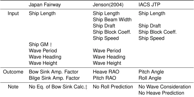
Among various empirical formulae of wave-induced motion, three methods are reviewed in this report; a)Japan Fairway Design guidance [7], b)Jenson(2004) [2] and c)IACS JTP rule [15]. The specific equations and procedures are described in Appendix B.2. The features of these three formulae can be summarized as Table 2.
Table 2: Comparison Table between Empirical Methods of Wave-induced Motion
Japan Fairway Jenson(2004) IACS JTP
Input Ship Length Ship Length Ship Length
Ship Beam Width
Ship Draft Ship Draft
Ship Block Coeff. Ship Block Coeff.
Ship Speed Ship Speed
Ship GM†
Wave Period Wave Period
Wave Heading Wave Heading
Wave Height Wave Height
Outcome Bow Sink Amp. Factor Heave RAO Pitch Angle
Bilge Sink Amp. Factor Pitch RAO Roll Angle
Note No Eq. of Bow Sink Calc.‡ No Roll Prediction No Wave Consideration No Heave Prediction † Distance between center of gravity and metacentre
‡ Instead of equation, graph is provided
As shown in Table 2, only a few parameters are necessary for estimation. Its calculation procedure is easy and straight forward. However, it is clear that the result of empirical formula has uncertainties because it can not consider the specific hull shape. Moreover, these formulae adopt several assumptions to allow for simplification of the problem. The first assumption is that the water is deep enough. Secondly, water area is assumed as open sea. These two assumption can cause an additional uncertainty when applying the empirical formula to a confined channel. As a result, it is important to identify the applica-tion limit.
Numerical Method for Wave-induced Motion
For more accurate prediction, the numerical method should be used instead of the empir-ical method. For a wave related problem, strip method or 3-dimensional panel method is widely implemented instead of general CFD tool to avoid high computational costs. In this
OCRE-TR-2013-048 3 PHASE I NRIM DEVELOPMENT
project, strip method is implemented to estimate wave-induced motion in open sea and restricted channel. The detailed theory and numerical scheme is described in Appendix B.3 and B.4.
Compared with the empirical method, numerical analysis requires detailed information on the hull shape. As well, the numerical method requires a larger computing time than the relatively instantaneous empirical computation. For example, the calculation time of the developed strip method software is summarized in Table 3.
Table 3: Example of Strip Method Calculation Time
Analysis input No of wave freq. 11
No of sections 27
No of grids per section 650
Computing time 193 min.
3.2 Maneuvering Model
This section describes the results of a literature review relating to maneuvering models to help guide the selection of methods to incorporate into NRIM. The Phase I NRIM ma-neuvering model is then described in general and a brief discussion of its performance is provided. A detailed description of the Phase I maneuvering model is provided in the Appendix A.
3.2.1 Maneuvering Model Literature Review
There are a number of different recognized methods available to predict the maneuvering performance of a vessel. These methods differ in terms of the amount of effort required, the accuracy of results and the computational time required for predictions. Typical meth-ods include: model testing, empirical computation, system identification, and CFD. There are also hybrid methods that have been published (e.g. model by Toxopeus [16]) which combine two or more of the aforementioned methods to obtain the desired output.
In general, there tends to be a link between the amount of effort (and cost) required and the accuracy of the results. Model testing is the most costly of the options and has a high level of accuracy in comparison with the other methods. The CFD method takes a large amount of effort and computing power. On the upside, CFD methods have been demonstrated to provide good results. System identification is a method of model optimization based on maneuvering trajectories from model or full scale tests. This is a relatively low-cost option but the accuracy results pend on the quantity and quality of the trajectories available for optimization. Prediction using existing empirical methods is relatively quick, easy and in-expensive. There has been extensive work completed in the area of empirical modeling
resulting in a number of documented and published models. A downfall of empirical predic-tions of maneuverability is that the accuracy is generally limited by the assumppredic-tions made in the model. A detailed description of the advantages and disadvantages of each method is provided in the proceedings of the 25th International Towing Tank Conference [17]. After considering all the prediction methods outlined above, it has been decided that the method that would work best to fulfil the needs of CCG is an empirical approach. This method would allow NRC to consider multiple vessels in different channel configurations in the relatively short project timeline. The use of other more complex methods would both extend the project delivery date and increase the project cost.
Selection of Mathematical Model
The use of an empirical method requires the use of a set of mathematical equations to represent a vessel maneuvering in a given waterway. A mathematical model based on the equations of motion is commonly used and is selected for use in this project. There are two general approaches to represent the loads on a given vessel within the mathematical model. The first is a whole vessel approach, which considers the overall loads on the entire vessel. The second is a modular approach, which considers the distinct loads on differ-ent sections of the vessel. The most common example of each approach are the Abkowitz model [18] and the Mathematical Modelling Group (MMG) model [19]. The Abkowitz model considers the global loads on the vessel in its entirety. The MMG model is modular in na-ture and considers the forces on the hull, rudder and propeller independently. When com-paring the two, the Abkowitz model requires more complex hydrodynamic derivatives than the MMG model and is used in published literature less frequently. In general a modular approach is less sensitive to the choice of maneuvering coefficients [17] in comparison to a whole vessel approach. These considerations lead to the selection of the MMG model for NRIM development.
The MMG model was originally proposed in 1976 by the Mathematical Modeling Group. To compute the forces and moments one must first calculate the hydrodynamic derivatives pertaining to the vessel of interest. These can be found using existing empirical or semi-empirical formulae that relate the hydrodynamic derivatives to the general particulars of a given ship. A number of this type of equations have been developed and published. A relatively recent study conducted by Toxopeus [20], investigated the performance of a num-ber of different empirical and semi-empirical equations used to compute the hydrodynamic derivatives. There were four different methods investigated including those by Kijima, et al. [21], Vassalos et al. [22], Clarke et al. [1] and Norrbin [23]. The formulations by Clarke compare relatively well to the values found experimentally for each vessel type considered. These equations directly relate the hydrodynamic coefficients to the principal particulars of a given vessel and are an improvement to methods based on flat-plate and slender body theory [1]. The Clarke equations are based on a linear regression analysis using over 70
OCRE-TR-2013-048 3 PHASE I NRIM DEVELOPMENT
experimental measurements of hydrodynamic derivatives for a wide range of different ship types.
The hydrodynamic derivatives are unique to the waterway that they were defined based on. The Clarke equations were derived from experimental data of vessels operating in deep water. Therefore, their applicability to shallow water scenarios may introduce additional er-rors. Complimentary equations were developed by Sheng [24] which corrected the Clarke, deep-water hydrodynamic equations and made them applicable to shallow water. This shallow-water correction is based on basic hull parameters of a given vessel. Since the Clarke equations appeared reasonable when compared to measured results, are related directly to basic hull parameters and have an available correction method for application to shallow water; they were selected for use for Phase I NRIM development.
The article by Toxopeus [20] also examined an approach to determine the hydrodynamic coefficients using a hybrid semi-empirical/CFD method as well as a method using just CFD. In general the hydrodynamic derivatives measured by these methods were much closer to the experimental measurements than those determined using the semi-empirical or empirical equations. In particular, the CFD based derivatives were often very close to the measured derivatives. However, the level of effort required to compute the hydrodynamic derivatives using these methods is much higher than what is required for a semi-empirical approach. The use of this method would require expertise in the area of CFD and would not be easily packaged into NRIM. However, it would be possible for NRC to compute hydrodynamic coefficients for select vessels using CFD to add to the NRIM database. This is outside of the scope of the current project but could be investigated in terms of required effort during Phase II for inclusion in the project report.
3.2.2 Phase I Maneuvering Model Description and Details
The simulation model is based on standard maneuvering equations of motion as outlined in Appendix A. The solution of these equations is achieved via the appropriate numeri-cal tools in MATLABTM [25]. There were two distinct maneuvering models considered in Phase I. The first model is two dimensional and considers a constant forward speed. The second model is three dimensional and accepts input relating to the engine setting. The speed can change throughout a maneuvering simulation with a given engine setting in the 3DOFs model. The maneuvering model requires the following inputs (propulsive and thruster forces only required for 3DOFs model):
• Environmental data
– Water depth, wind speed and direction, current speed and direction
– Beam at waterline, length at waterline, draft, block coefficient, displacement,
rudder area, rudder lift coefficient, projected areas exposed to wind and cur-rent, drag coefficients for wind and curcur-rent, moment of inertia about vertical axis through ship’s waterplane centre, location of centre of gravity relative to ship centre, propulsive forces at various settings, thruster forces.
• Maneuvering Coefficients (Hydrodynamic Derivatives)
– Details of the meaning of these coefficients are elucidated in Appendix A.
The maneuvering coefficients can be determined for a particular vessel either through model testing (Planar Motion Mechanism (PMM)), sea trials, or by using CFD codes to emulate the PMM tests. For this study, we have used the coefficients presented by Clarke et al. [1] which were derived from analytical and empirical methods. These coefficients depend on hull geometry and are to be regarded as valid about a nominal operating surge speed. This is also evident from the derivation presented in Appendix A. The hydrodynamic coefficients used here must therefore be considered as approximations to the coefficients appropriate to the vessels of interest to the Canadian Coast Guard. We note further that Clarke provides shallow water corrections to these coefficients. Verification of these cor-rections can be performed by CFD studies.
3.2.3 Maneuvering Model Output and Performance
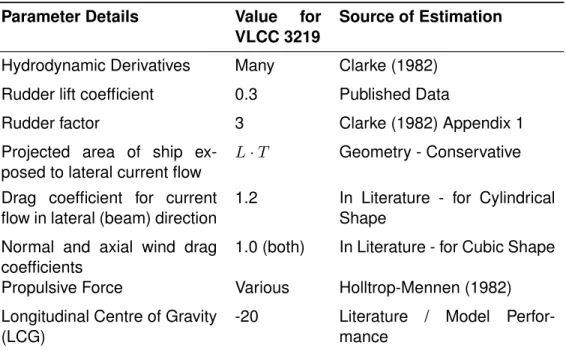
We remark that the simulations were compared to the results of sea trials performed by another client, the details of which we are not at liberty to report. General ship’s particulars were used to estimate the hydrodynamic coefficients for sway and yaw based on the work of Clarke et al. [1]. The following additional parameters were estimated: hydrodynamic coefficients in surge, location of centre of mass, propeller thrust, drag coefficients for wind and current. The results of a simulation with 35 degree rudder angle to starboard compare well with the sea trials.
3.3 Decision on Shallow and Open Water
Generally, if the ratio of the water depth to the ship’s draft (H/T) is around 1, it can be considered as ”shallow water.” However, there is no absolute criterion, because various naval architectural problems are based on very different backgrounds. For the free surface wave problem (e.g. wave-induced motion), when the ratio of the water depth to the wave length is smaller than 0.05, it is considered as shallow water. On the other hand, when evaluating the squat effect, the ratio of the water depth to the ship’s draft is the important parameter to assess the water depth. Furthermore, every empirical formula for the squat prediction has its own criterion of what is considered shallow water. As a result, NRIM will automatically choose the proper (shallow or deep water) model considering the given
OCRE-TR-2013-048 3 PHASE I NRIM DEVELOPMENT
conditions and theoretical background. In other words, the user does not need to input into NRIM weather the scenario being assessed is in shallow or deep water. Instead, NRIM will internally decide this and select the appropriate empirical relations, based on the criterion around which the relations were formulated.
The term ”open water” indicates that there is no obstacle in the water way. In contrast, a confined (or restricted) channel describes a channel which contains an obstacle, such as a close proximity bank. Similar to the discussion on shallow versus deep water, the empirical equations considered in NRIM to account for narrow channel effects each have different significant parameters that consider the significance of narrow-channel effects. As such, the narrow channel versus open water distinction will be made internally, within NRIM. It should be noted that the distinction between open water and narrow channels, as well as deep water versus shallow water, is based on the significance of the effect of narrow channels or shallow water on the parameter being predicted. Therefore, pending on the empirical relation selected within NRIM to compute the parameter of interest, the effect may vary.
4
PHASE I SCENARIO DETAILS
The scenario to consider for Phase I development of NRIM was based on the availability of comparative data to support validation of model output. The CCG has provided NRC with access to a collection of reports that detail a comprehensive study that was conducted to investigate a set of tanks operating in waterways through Kitimat, British Columbia. The primary report entitled: “Maneuvering Study of Escorted Tankers to and from Kitimat,” [3] assessed the maneuvering performance of four tankers. A secondary report entitled “Section 3.6: Special Underkeel Clearance Survey,” [26] considered the MDA requirement for the largest of the tankers reviewed in the maneuvering study. A third report entitled “Appendix F: Additional Maneuvering Results and Parameters,” [27] provided additional maneuvering simulations for the tankers.
The primary maneuvering report provided simulated results for each of the four indepen-dent tankers in deep open water. The report documented simulated results of the following maneuvers: turning circles, speed acceleration maneuvers and zig-zag maneuvers. There was also crash stop data provided but this is not considered in the Phase I comparison since limited propulsive information was available to feed into the NRIM. The supplemen-tary report containing the content of Appendix F, provided simulated results of the tankers turning circle in open, shallow water. The shallow water turning circle was simulated for a water depth of 25.32 m. The MDA assessment, as detailed in the Section 3.6 supple-mentary report, was carried out for shallow, open water, similar to certain portions of the Kitimat channels under consideration. Considerations of squat were computed at a range of different shallow water depths between 30 and 50m.
4.1 Vessel Details
For Phase I, the largest vessel considered in the Kitimat study, a loaded VLCC (VLCC 3219), was selected for investigation. This vessel was selected for two key reasons. The first reason was that there were ample maneuvering results available from the primary and secondary maneuvering reports for this particular vessel. The maneuvering results were output from a FORCE technology simulator. This type of simulator has been used opera-tionally for many years and was used in the Kitimat study to investigate the maneuvering performance of tankers. The second reason for selecting this particular vessel is that there were considerations into the MDA for this vessel provided in the Section 3.6 supplementary report. As part of the Kitimat study, only the largest tanker (VLCC 3219) was investigated for MDA requirements and therefore, there was no comparative data available for the other three tankers considered in the study. The general particulars of the Phase I vessel are summarized in Table 4.
Though this vessel was selected for demonstration in Phase I, it is important to note that the preliminary NRIM, developed in Phase I can presently be used to investigate maneuvering