Publisher’s version / Version de l'éditeur:
Journal of Thermal Spray Technology, 15, 4, pp. 676-681, 2006-12-01
READ THESE TERMS AND CONDITIONS CAREFULLY BEFORE USING THIS WEBSITE. https://nrc-publications.canada.ca/eng/copyright
Vous avez des questions? Nous pouvons vous aider. Pour communiquer directement avec un auteur, consultez la première page de la revue dans laquelle son article a été publié afin de trouver ses coordonnées. Si vous n’arrivez pas à les repérer, communiquez avec nous à PublicationsArchive-ArchivesPublications@nrc-cnrc.gc.ca.
Questions? Contact the NRC Publications Archive team at
PublicationsArchive-ArchivesPublications@nrc-cnrc.gc.ca. If you wish to email the authors directly, please see the first page of the publication for their contact information.
NRC Publications Archive
Archives des publications du CNRC
This publication could be one of several versions: author’s original, accepted manuscript or the publisher’s version. / La version de cette publication peut être l’une des suivantes : la version prépublication de l’auteur, la version acceptée du manuscrit ou la version de l’éditeur.
For the publisher’s version, please access the DOI link below./ Pour consulter la version de l’éditeur, utilisez le lien DOI ci-dessous.
https://doi.org/10.1361/105996306X147072
Access and use of this website and the material on it are subject to the Terms and Conditions set forth at
Suspension plasma spraying of nanostructured WC-12Co coatings
Oberste Berghaus, J.; Marple, B. R; Moreau, C.
https://publications-cnrc.canada.ca/fra/droits
L’accès à ce site Web et l’utilisation de son contenu sont assujettis aux conditions présentées dans le site LISEZ CES CONDITIONS ATTENTIVEMENT AVANT D’UTILISER CE SITE WEB.
NRC Publications Record / Notice d'Archives des publications de CNRC:
https://nrc-publications.canada.ca/eng/view/object/?id=a86fb61e-2bb2-482b-b9d5-c038b1cebe81 https://publications-cnrc.canada.ca/fra/voir/objet/?id=a86fb61e-2bb2-482b-b9d5-c038b1cebe81Suspension Plasma Spraying of
Nanostructured WC-12Co Coatings
J. Oberste Berghaus, B. Marple, and C. Moreau
(Submitted February 27, 2006; in revised form April 19, 2006)
Nanostructured WC-12% Co coatings were deposited by suspension plasma spraying of submicron feed-stock powders, using an internal injection plasma torch. The liquid carrier used in this approach allows for controlled injection of much finer particles than in conventional thermal spraying, leading to thin coatings with a fine surface finish. A polyethylene-imine (PEI) dispersant was used to stabilize the colloidal suspension in an ethanol carrier. In-flight particle states were measured for a number of operating conditions of varying plasma gas flow rates, feed rates, and standoff distances and were related to the resulting microstructure, phase composition (EDS, SEM, XRD), and Vickers hardness. High in-flight particle velocities (>800 m/s) were generated, leading to dense coatings. It was observed that the coating quality was generally compro-mised by the high temperature and reactivity of the small particles. To compensate for this shortcoming, the suspension feed rate was adjusted, thereby varying the thermal load on the plasma. Results showed that a slightly larger agglomerate size, in conjunction with low particle jet temperatures, could somewhat limit the decomposition of WC into brittle W2C/W3C and amorphous cobalt containing binder phases.
Keywords nanostructured coatings, suspension plasma spraying, tungsten-carbide cobalt
1. Introduction
WC-Co cermet coatings, produced by thermal spraying, are used extensively in industrial wear applications. Their mechani-cal properties are a strong function of the carbide grain size, the binder volume fraction, and the extent to which the carbides are homogeneously distributed in the binder phase. Nanostructured WC-Co coatings can potentially exhibit improved hardness, toughness, and wear resistance over conventional tungsten carbide materials when processed under optimized conditions (Ref 1). A reported increase in hardness is attributed to the de-crease in grain size and reduction in the mean free path of the cobalt matrix. A fine starting powder with submicron grains fa-vors a homogenous distribution of the carbides within the matrix and can furthermore lead to low surface roughness, requiring little additional surface finishing (Ref 2). The potential for such improvements is generating considerable interest in developing techniques for producing these coatings.
The highest hardness and wear performance of conventional tungsten carbide materials is generally obtained by those pro-cessing methods that impart high in-flight particle velocities and low particle temperatures during spraying. High particle speeds have been shown to reduce coating porosity, and low particle temperatures limit the decomposition of the carbide into brittle W2C, W3C, and metallic tungsten, as well as the dissolution of
the cobalt binder into a weak amorphous phase. As a result, high-velocity oxyfuel (HVOF) thermal spraying has been established as a preferred method over plasma spraying (Ref 3-5). To pro-cess a nanostructured feedstock powder by HVOF, the initial cermet constituents are generally agglomerated and sintered into spherical particles of larger particle size (5-40 µm), allowing standard powder feeding (Ref 1-5).
Suspension plasma spraying using a liquid feedstock carrier is an emerging technology that permits projection of much finer starting powders directly without the need to preform and con-solidate spherical feed agglomerates. In this process, a feed sus-pension is injected at high velocity into the plasma flame. The plasma-liquid interaction atomizes the suspension into a fine mist and evaporates the suspension medium, thereby concentrat-ing the solid content into microsized particles. The small par-ticles are then nearly immediately accelerated to the plasma gas velocity (Ref 6). Upon impact on the substrate, these particles form thinner lamellae than in conventional spraying (Ref 7). Thin coatings (20-100 µm) with more refined microstructures (Ref 6) and potentially smoother surface finishes are created. In spite of the high plasma temperature, the particle temperature and decomposition of the tungsten carbide material is, in prin-ciple, reduced by the evaporating liquid carrier, which imposes a substantial thermal load on the plasma. The evaporating liquid cools the forming particles and delays the onset of overheating. In this study, the potential of this technique for consolidating nanostructured tungsten carbide cermet materials is explored. The suspension feedstock is axially injected into the center of three converging plasma streams of a Mettech Axial III plasma torch (Northwest Mettech Corp., Richmond, BC, Canada). High gas velocities, up to 1000 m/s (nearly approaching those of HVOF systems), can be generated with this torch. A procedure to prepare the liquid suspension is described. In-flight particle velocity and temperature are measured for different operating conditions of the torch, suspension feed rates, and standoff dis-tances and are related to the resulting microstructure of the coat-ing. Two different powder raw materials are compared, and the This article was originally published in Building on 100 Years of
Suc-cess, Proceedings of the 2006 International Thermal Spray Conference (Seattle, WA), May 15-18, 2006, B.R. Marple, M.M. Hyland, Y.-Ch. Lau, R.S. Lima, and J. Voyer, Ed., ASM International, Materials Park, OH, 2006.
J. Oberste Berghaus, B. Marple, and C. Moreau, Industrial Materials
Institute, NRC, Boucherville, Québec, Canada Contact e-mail: jorg.oberste-berghaus@cnrc-nrc.gc.ca. JTTEE5 15:676-681 DOI: 10.1361/105996306X147072 1059-9630/$19.00 © ASM International
Peer
Reviewed
effect of oxygen exclusion by the use of a shroud gas is investi-gated. Finally, possible process improvements are delineated.
2. Experimental Procedures
2.1 Spray Parameters and Material Characterization
The suspension spraying system used a Mettech Axial III plasma torch (Northwest Mettech Corp., North Vancouver, BC, Canada) equipped with an internal injection/atomization mod-ule, with nitrogen as the atomizing gas. The suspension was de-livered by a positive-displacement dosing pump from an agi-tated reservoir and measured by a precision flow meter. By ensuring continuous flow and agitation in all wetted conduits during spraying and idle operation, sediment formation, which can cause malfunction of the solenoid valves and injector, was avoided. In an attempt to generate high particle velocities, the plasma was operated at two selected conditions with high plasma gas flow rates, as summarized in Table 1. To minimize electrode erosion, the current was adjusted to limit the torch power to ∼90 kW.
In-flight particle states were measured with a commercial di-agnostic system (AccuraSpray G2, Tecnar, St-Bruno, QC, Canada). The temperature measurement is based on two-color pyrometry, and velocity is determined by a time-of-flight tech-nique. The measurement volume was centered in the spray plume at the location of the substrate during deposition, i.e., at 50 and 62.5 mm. Because the small size of the particles prevents individual in-flight particle detection, an ensemble particle di-agnostic system, which senses the fluctuations of the total emit-ted radiation in the field of view, is deemed necessary (Ref 6).
Microstructures were observed by scanning electron micros-copy (SEM) (JSM-610, JEOL, Tokyo, Japan) and field-emission scanning electron microscopy (FE-SEM) (S4700, Hitachi, Tokyo, Japan). The samples were prepared by standard metallographic methods. Porosity was assessed on the cross section by SEM (10,000×), using image analysis. Such high magnification was judged most suitable to capture the finely structured porosity in the coatings. The intensity range and thresholds were standardized on reference materials, and five measurements were averaged per sample. Vickers microhard-ness measurements were performed under a 300 g load for 20 s on the cross section of the coatings. Ten measurements were taken per sample at randomly selected locations.
Phase analysis was carried out by x-ray diffraction (XRD) using a Bruker D8-Discovery diffractometer (Bruker AXS, Inc., Madison, WI) with Cu K␣ radiation at an acquisition of rate of 0.01°/s. The measurement is an average over a substrate area between 2 and 10 mm2, depending on the diffraction angle. To
qualitatively describe the degree of carbide degradation, two ra-tios of XRD reflection peak areas are defined. An index of crys-tallinity (IC) measures the area of crystalline peaks between 30 and 54° versus the total integrated area in this region, including
the diffuse amorphous hump. This index reflects the transforma-tion of cobalt binder into a weak amorphous/ (CoxWyCz) phase.
Furthermore, an index of WC carbon compares the area of the principal WC reflection with the sum of the areas of the principal lines of all WxC phases, including W, WC, W2C, and W3C. The
loss of carbon is thought to occur as a result of direct oxidation on the surface of solid WC, leading to formation of non-WC phases (Ref 1). This index is an indication of the degree of oxi-dation of the carbides. Although these indexes do not precisely quantify the degree of degradation, they allow here an approxi-mate comparison between the coatings obtained at different spray conditions.
2.2 Materials and Suspensions
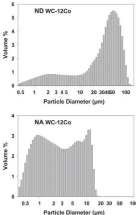
Two different feedstock materials of WC-12% Co were used in this study, namely, a soft-agglomerated powder with a nomi-nal carbide grain size of 60-250 nm (Nanostuctured & Amor-phous Materials, Houston, TX), subsequently referred to as “NA,” and an agglomerated and sintered powder with a carbide grain size 40-80 nm (formerly Nanodyne, Inc., New Brunswick, NJ), subsequently referred to as “ND.” The particles of the latter material, ND, were found to disintegrate into its finer constitu-ents. Particle size distributions of the starting powders were measured with a Coulter LS (Hialeah, FL) particle size analyzer and are shown in Fig. 1.
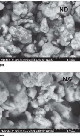
The morphologies and phase composition of the powders were verified by high-resolution FE-SEM and XRD, shown in the micrographs in Fig. 2 and the spectra in Fig. 3. Suspensions of 20 wt.% NA solids in ethanol (1.37 vol.%) and of 15 wt.% ND solids (1.06 vol.%) in a mixture of ethanol and 25% ethylene
Table 1 Plasma operating conditions
Condition Torch current, ×3 Gas flow, SLPM Ar, % N2, % H2, % Power, kW 1 200 A 245 75 10 15 83.2 2 190 A 275 75 15 10 90.1
Fig. 1 Particle size distribution of feedstock powders before milling.
Peer
glycol were prepared. The addition of the viscous glycol (b.p. 200 °C) is expected to stabilize the suspension and impose an additional thermal load on the plasma during spraying.
The high specific density of WC-Co powders and the widely different acid/base properties of the two main particulate con-stituents (WC, or rather the surface oxide WO3,is a Lewis acid
and CoO is basic) make this system difficult to disperse in a suspension. Polyethyleneimine (PEI) (MW 25,000, Alfa Aesar, Ward Hill, MA) was used as dispersing agent. This cationic polyelectrolyte adsorbs onto the tungsten oxide surfaces and can be charged positively by protonation of the amine groups, i.e., by adjusting the pH to less basic conditions (Ref 8). Care must be taken not to add too much acid in the pH adjustment and thereby cause dissolution of cobalt according to the reaction CoO + H2O ↔ Co
2+
+2OH−, which increases the pH and thereby effectively buffers the system (Ref 9). Suspensions were prepared in ethanol by mixing 80 wt.% powder, PEI (0.6 wt.% per solids), and an appropriate amount of WC grinding balls in a 2 L polyethylene milling jar. Milling was needed to break down the particle agglomerates and was performed at a speed of 140 rpm for 24 h. After washing of the ball mill and medium, the pH was immediately adjusted by addition of 1 M HCl to a final value between pH 8 and 9, at which point the solution starts buffering, i.e., no further decrease in pH was possible by acid addition. The effectiveness of the milling procedure, dispersing agent, and pH adjustment was qualitatively assessed by sedimentation tests. The procedure outlined above stabilized the dispersion suffi-ciently to be compatible with the spray process. Addition of
vis-cous ethylene glycol, as in the case of the ND feedstock, further prolonged the settling time of the suspension.
2.3 Substrate Considerations
Coatings were produced on mild steel substrates with dimen-sions of 25 × 75 × 12.5 mm. To increase coating adhesion, the substrate surface was grit-blasted with 60 grit Al2O3particles
prior to deposition. Initially, high substrate temperatures pro-voked oxidation of the coating surface after each torch pass and led to detachment of each subsequent layer. Backside cooling of the substrate using both compressed air and water was conse-quently implemented. Compressed air cooling on the front sur-face of the substrate, i.e., where the coating is deposited, was observed to deflect the particle jet issuing from the torch and posed the risk of adversely affecting the resulting coating. At-tempts were made to reduce the cooling air jet flow while main-taining a surface temperature not exceeding 200 °C.
3. Results and Discussion
3.1 Processing Conditions and Particle States The effect of processing conditions was mainly assessed on the 20 wt.% NA (WC-12Co) suspension in ethanol. Measured particle states for selected operating conditions of varying plasma gas flow, suspension flow rate, and standoff distance are summarized in Table 2.
With an increase in gas flow rate (plasma condition 2), par-ticle velocities up to 800 m/s could be generated. Such high ve-locities are rarely attained in atmospheric plasma spraying. The high particle velocities are the result of the small particle size and high gas velocity. The small particles have been shown to intimately follow the gas flow velocity as they are entrained in the plasma stream (Ref 6). However, this particle speed is rap-idly lost at increasing spray distance, as seen from the measure-ment at 62 mm standoff. Previous work has shown that the im-pact velocities on the substrate are reduced from the free stream values but scale strongly with free stream conditions (Ref 6).
High average particle temperatures between 2180 and 2440 °C were measured. For optimized HVOF spray conditions, using 5-40 µm feed agglomerates, particle temperatures are usu-ally much lower (1600-2000 °C) but are reported to increase
Fig. 2 Morphology of feedstock powders (a) ND and (b) NA after milling, showing angular submicron carbide constituents
Fig. 3 XRD spectra of feedstock powders
Peer
with decreasing particle size (Ref 1). The much smaller particle sizes, generated from the suspension, likely govern the attain-able temperature range. Nonetheless, particle temperatures were reduced from 2432 to 2180 °C by increasing the suspension feed rate from 1.5 to 3.5 kg/h (see NA-3 to NA-1). Concurrently, particle speeds of ∼700 m/s were maintained. The lowest tem-perature was also obtained by changing the suspension carrier to a high boiling point medium, such as ethylene glycol (ND-1), using a high feed rate. The total thermal load on the plasma is thereby used as an independent tuning parameter for the particle temperature. It should be mentioned that the use of a slightly larger torch exit nozzle for the ND-1 sample explains the lower particle velocity of 600 m/s.
3.2 Coating Structure and Phase Composition The microstructures of the coatings are shown in Fig. 4 and 5. Depending on the operating conditions and the feeding rates, deposition rates varied from ∼1.3 to 2.8 µm/pass. A pass consti-tutes a scan pattern of the torch covering the entire area of the substrate. Coatings up to 150 µm thick were produced. The ini-tial layers of the coating filled the original surface features of the grit-blasted substrate, resulting in a final surface roughness of Ra< 3 µm, as measured with a profilometer. This roughness is
sufficient for some industrial applications, or if finishing steps are needed, polishing is likely facilitated over conventional WC-Co coatings (Ref 3).
Coating porosities varied from 9 to <0.2%. The low porosity comes, however, at the expense of substantial degradation of the WC-Co. XRD spectra of the coatings in Fig. 6 reveal a strong
presence of W2C, W3C, and even metallic W, as well as a
char-acteristic amorphous “hump” in the region of 35-54°. Some de-composition of small WC grains in thermal spraying is usually reported and is attributed to the increased reactivity of the fine carbide particles (Ref 1, 3). In addition, the agglomerate par-ticles created from the suspension are much smaller than for con-ventional spraying, further elevating surface reactivity. 3.3 Microstructure, Composition, and Mechanical
Properties
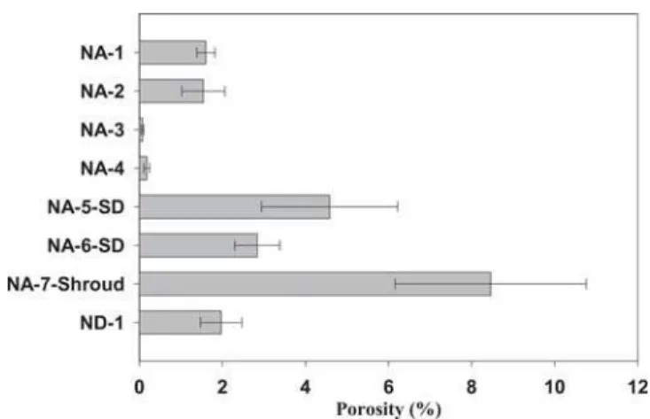
Mechanical properties of WC-Co coatings, such as hardness, strongly depend on both the porosity and the quality of carbide after processing (Ref 1). Indices of crystallinity and WC carbon content are summarized in Fig. 7, and porosity values for the selected coatings are shown in Fig. 8. The hardness values, de-termined for these coatings, are shown in Fig. 9.
Distinct carbide degradation in terms of a decrease in WC carbon content and a low degree of crystallinity for samples NA-1 through NA-3 are observed in Fig. 7. As explained above, the samples were formed at particle temperatures increasing from 2180 to 2430 °C at similar particle velocity. Although the sample obtained with the hottest particles (NA-3) shows very low porosity values (<0.2%), its hardness decreased substan-tially. The higher particle temperature not only increases the re-activity of the surface for oxidation but also fosters more rapid dissolution of the fine-scale WC grains into the liquid metal dur-ing spraydur-ing (Ref 3). The microstructure in Fig. 10(a), for ex-ample, shows only few angular-shaped carbide constituents and is dominated by rounded and deformed features, which have likely undergone degradation. The corners and edges of the
car-Table 2 Particle states at selected spray conditions for
plasma settings from Table 1(a) Sample Plasma condition Susp. FR, kg/h SD, mm Vpart., m/s Tpart., °C NA-1 1 3.6 50 714 2179 NA-2 1 2.5 50 706 2254 NA-3 1 1.5 50 737 2432 NA-4 2 2.5 50 790 2293 NA-5-SD(b) 1 2.5 62 642 2279 NA-6-SD(b) 2 3.5 62 754 2261 NA-7-SH(c) 1 2.5 114 277 2439 ND-1 1 3.0 50 608 2202
(a) FR, feed rate; NA, nanostructured and amorphous materials; ND, nano-dyne. (b) SD, spray distance at 62 mm. (c) SH, gas shroud installed
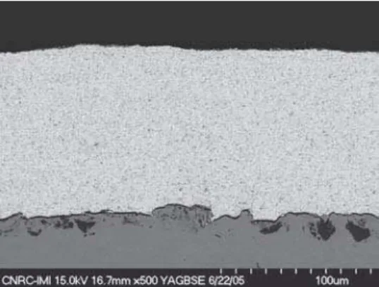
Fig. 4 Cross-section micrograph for coating NA-2
Fig. 5 Microstructures of (a) NA-2 and (b) NA-4
Peer
bide are more readily dissolved because of the added reactive contact area to the cobalt.
The effect of coating porosity on microhardness is illustrated by comparing samples NA-2 and NA-4. These samples were produced at similar particle temperature (2250 °C) but different particle velocity, i.e. 700 and 790 m/s. With increasing velocity, a densification from 1.5 to <0.2% porosity was induced (Fig. 8). The decreased porosity resulted in one of the harder coatings (∼700 HV0.3) of this study.
An increase in spray distance from 50 to 62 mm resulted in a softer coating for both plasma conditions (conditions 1 and 2). Sample NA-5-SD has higher porosity and a lower hardness than the corresponding sample NA-2. A similar trend can be seen by comparing NA-6-SD to NA-4. In both cases, a drop in particle
velocity was measured. Furthermore, the coatings obtained at larger standoff distances were more degraded and oxidized (Fig. 7, 8, and 9).
It is interesting to note that the deposits obtained at condition 2, i.e., at higher jet velocities (NA-4 and NA-6-SD), show a lower WC carbon index than those at condition 1 (NA-2 and NA-5-SD), even though they have an equal or higher degree of crystallinity. At high particle velocities, very small particles, even those that travel on the periphery of the principal particle jet, may be incorporated into the coating. Those particles, in turn, are most likely to be oxidized, due to their proximity to the surrounding air and to their elevated surface reactivity. At lower velocity, the very small particles are prevented from reaching the substrate because they are entrained in the radially deflecting gas flow in front of the substrate (Ref 6). Layers of oxidized particles can be identified in the microstructure of those coatings (Fig. 4 and 5b, see arrows), appearing as dark strata in the back-scattered electron image. The arrows in Fig. 5 indicate some of these darker strata. EDX measurements confirmed higher oxy-gen content in the dark strata as compared with the bordering lighter layers. A coating layer is formed at each pass of the torch, following a raster pattern and covering the adjacent layers with the oxidized particles. Oxidation of the exposed top surface of the coating after each pass may also play a role.
Fig. 6 XRD spectra of selected coatings
Fig. 7 Summary XRD analysis, index of WC carbon, and index of crystallinity
Fig. 8 Porosity values for selected coatings from SEM image analysis (original magnification, 10,000×)
Fig. 9 Hardness HV0.3for selected samples
Peer
The use of an argon shroud, shielding the plasma and particle jet from air entrainment, resulted in a substantial reduction in oxidation. A high index of WC carbon is measured in the result-ing coatresult-ing (NA-7-Shroud in Fig. 7). However, the shroud at-tachment necessitates large spray distances, and the radial argon jet disturbed the plasma flow, leading to low particle velocities and high particle temperatures. The coatings have very high po-rosities, low crystallinity, and, consequently, low hardness values. The hardest coating in this study was obtained with the Nano-dyne powder (ND-1) suspended in an ethanol/ethylene-glycol carrier. The high boiling point medium, in conjunction with a high feed rate, was anticipated to reduce the in-flight particle temperatures and delay the onset of overheating of the small particles while stabilizing the suspension. Indeed, the highest index of crystallinity and WC carbon content were measured for this coating, as seen in Fig. 7. The microstructure, shown in Fig. 10(b), reveals a higher number of angular carbides, as indi-cated by the arrows. Also, the degree of oxidation in this coating is reduced. A more agglomerated feedstock, even after ball mill-ing, may have led to less dispersion of submicron particles by the plasma flame or may have lowered the reactivity of the particles. A lesser degree of atomization of the viscous glycol mixture may also reduce the amount of overspray oxides deposited. Because of the relatively low particle velocity of only 600 m/s, ND-1 is not the densest coating in this study. An additional increase in hardness could be expected at higher velocities.
Ultimately, the obtained hardness values in this preliminary study are far below the values reported in the literature for both conventional (Ref 1) and nanostructured WC-Co coatings (Ref 3-5) sprayed by HVOF, which are on the order of 1000-1550 Hv0.3. On the other hand, suspension spraying showed the
potential to produce very dense coatings with a relatively smooth surface finish. The principal obstacle is the high reactiv-ity of the small particles, which degrade easily during the spray process. Careful adjustments of the spray conditions and feed-stock preparation are possible avenues for reducing particle tem-perature, carbide degradation, and oxide deposition and thereby improving coating properties.
4. Conclusions
• The potential of suspension plasma spraying as a novel method for the consolidation of nanostructured WC-Co coatings is explored. The high particle velocities, the small splat sizes, and the possible control of the particle tempera-ture make this technique a promising candidate.
• Coating hardness is a strong function of porosity and degree of carbide degradation. Porosity was decreased to <0.2% with increasing particle velocities up to 800 m/s.
• The degree of degradation of carbides and binder into amor-phous phases is reduced at lower particle temperature. Lower temperatures are induced by varying the suspension feed rate and increasing the total thermal load. Because of the small particle size, however, temperatures below 2200 °C could not be produced.
• The measured carbon loss in the carbide is principally associ-ated with deposition of layers of highly oxidized overspray. • The properties of the feedstock powder and feed suspension
play a critical role in carbide quality in the resulting coating. • The principal limitations to produce coatings of comparable hard-ness to those from established technologies were identified to be the high reactivity of the small particles during spraying, leading to degradation and oxidation of the carbide phase.
References
1. J. He and J.M. Schoenung, A Review on Nanostructured WC-Co Coat-ings, Surf. Coat. Technol., 2002, 157, p 72-79
2. F. Fischer, M.D. Dvorak, and S. Siegmann, Development of Ultra Thin Carbide Coatings for Wear and Corrosion Resistance, Thermal Spray
2001: New Surfaces for a New Millennium (Singapore), C.C. Berndt, K.A.
Khor, and E.F. Lugscheider, Ed., ASM International, 2001, p 1131-1135 3. D.A. Stewart, P.H. Shipway, and D.G. McCarteny, Abrasive Wear
Be-haviour of Conventional and Nanocomposite HVOF-Sprayed WC-Co Coatings, Wear, 1999, 225-229, p 789-798
4. J. Voyer and B.R. Marple, Thermal Spray Processing of WC-Co Nano-materials, Thermal Spray: Surface Engineering via Applied Research, C.C. Berndt, Ed., May 8-11, 2000 (Montréal, Québec, Canada), ASM International, 2000, p 895-904
5. B.R. Marple and R.S. Lima, Process Temperature/Velocity-Hardness-Wear Relationships for High-Velocity Oxyfuel Sprayed Nanostruc-tured and Conventional Cermet Coatings, J. Therm. Spray Technol., 2005, 14(1), p 67-76
6. J. Oberste Berghaus, S. Bouaricha, J.-G. Legoux, and C. Moreau, Sus-pension Plasma Spraying of Nanoceramics Using an Axial Injection Torch, Thermal Spray Connects: Explore Its Surfacing Potential, E. Lugscheider and C.C. Berndt, Ed., May 2-4, 2005, 2005 (Basel, Swit-zerland), ASM International
7. P. Fauchais, Understanding Plasma Spraying, J. Phys. D, Appl. Phys., 2004, 37, p R86-R108
8. E. Laarz and L. Bergström, Dispersing WC-Co Powders in Aqueous Media with Polyethylenimine, Int. J. Refract. Met. Hard Mater., 2000,
18, p 281-286
9. K.M. Andersson and L. Bergström, Aqueous Processing of WC-Co Powders: Suspension Preparation and Granule Properties, Ceram.
Trans., Colloid. Ceram. Process., 2004, 152, p 93-107 Fig. 10 Microstructure of samples (a) NA-4 and (b) ND-1
![[PDF] Tutoriel Painter : Création d'un encadrement | Cours informatique](data:image/gif;base64,R0lGODlhAQABAIAAAP///wAAACH5BAEAAAAALAAAAAABAAEAAAICRAEAOw==)