HAL Id: hal-01158570
https://hal-mines-paristech.archives-ouvertes.fr/hal-01158570
Submitted on 1 Jun 2015
HAL is a multi-disciplinary open access archive for the deposit and dissemination of sci-entific research documents, whether they are pub-lished or not. The documents may come from teaching and research institutions in France or
L’archive ouverte pluridisciplinaire HAL, est destinée au dépôt et à la diffusion de documents scientifiques de niveau recherche, publiés ou non, émanant des établissements d’enseignement et de recherche français ou étrangers, des laboratoires
Fostering energy efficiency in buildings through
aerogel-based renders
Mohamad Ibrahim, Etienne Wurtz, Patrick Achard, Pascal Henry Biwole
To cite this version:
Mohamad Ibrahim, Etienne Wurtz, Patrick Achard, Pascal Henry Biwole. Fostering energy efficiency in buildings through aerogel-based renders. ICAE 2015, May 2015, Donostia San Sebastián, Spain. pp.369-378. �hal-01158570�
Fostering energy efficiency in buildings through aerogel-based
renders
Mohamad Ibrahim1*, Etienne Wurtz2, Patrick Achard1, Pascal H. Biwole1,3
1MINES ParisTech, PSL Research University, PERSEE, Centre Procédés, Energies Renouvelables et
Systèmes Energétiques, 1 Rue Claude Daunesse - CS 10207 - F-06904 Sophia Antipolis Cedex, France
2 CEA-INES, LEB - Building Energy Lab, 50 av. du Lac Léman, 73377 Le Bourget du Lac, France 3 Department of Mathematics and Interactions, University of Nice Sophia-Antipolis, Nice, France
*e-mail: mohamad.ibrahim@mines-paristech.fr
Key words: aerogel-based rendering, energy efficient envelopes, building rehabilitation, thermal insulation.
Abstract
In France, the building sector is the largest consumer of energy and accounts for about 43% of the total energy consumption and 25% of the CO2 emissions. In this study, we present a recently developed
insulating rendering based on silica-aerogels. It is mainly developed for exterior thermal insulation applications. In addition to new buildings, it can be used for retrofitting existing ones since it has a high insulation performance and its application is compatible with the traditional masonry facades using the well-known ordinary techniques. The objectives are to examine the hygrothermal performance of exterior walls and to estimate the energy performance of houses with and without this rendering. On an envelope scale, numerical simulations are carried out using the software WUFI. The latter solves the coupled heat and moisture transfer within a multi-layered wall. On a full-scale house, the energy performance is estimated by the aid of numerical simulations using the whole building energy simulation program EnergyPlus. Results have shown that adding the aerogel-based rendering reduces significantly the heat losses as well as the moisture risks.
1 Introduction
In France, the building sector is the largest consumer of energy and accounts for about 43% of the total energy consumption [1]. This energy consumption contributes to producing around 25% of CO2
emissions. The building sector offers significant potential for improved energy efficiency through the use of high-performance insulation and energy-efficient systems. For existing buildings, renovation has a high priority in many countries, including France, because these buildings represent a high proportion of energy consumption and they will be present for decades to come. Several studies [2, 3, 4] showed that the most efficient way to curb the energy consumption in the building sector (new and existing) remains the reduction of the heat losses by improving the insulation of the building envelope. For retrofitting and even for new buildings in cities, the thickness of internal or external insulation layers becomes a major issue of concern.
Since their first discovery in the 1930’s [5], aerogels have shown a great progress in the last decades. Due to their superior characteristic, they are used in different sectors including buildings, electronics, clothing, space applications, etc. However, the cost of the aerogel-based insulation materials remains high compared to conventional insulation that hinders their entry to the market. Research is still continuing to develop more advanced technologies to lower the aerogel’s production costs and enhance their performance.
This study presents a recently developed insulating rendering based on the (super)-insulating materials silica aerogels which is mainly intended to be used for exterior thermal insulation systems. The hygrothermal performance of exterior envelopes covered with this aerogel-based rendering is analysed. Also, the energy performance of houses of different construction techniques is estimated before and after applying the rendering on the exterior facades.
2 Aerogel-based rendering
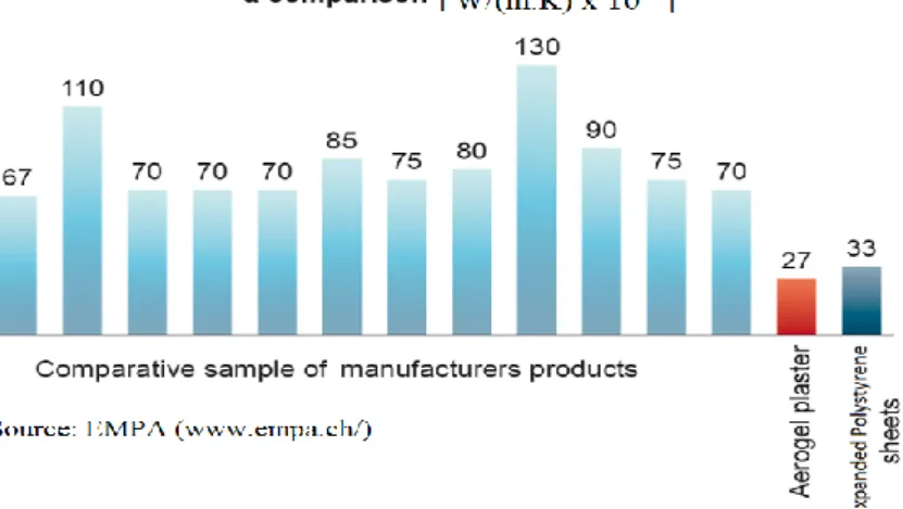
A very limited number of studies exist on aerogel-based thermal insulating plasters. Barbero et al. [6] provided an overall analysis of thermal insulating plasters in the European market. They concluded that innovative solutions for thermal insulating plasters based on materials with pore size in nanometer range, such as aerogel, could make a significant contribution to this field, reaching higher level of thermal performance and reducing the needed thickness. Additionally, successful approaches will have the ability to be used on both new and existing buildings, using techniques that are familiar to today's construction industry. According to the authors, thermal insulating plasters have the advantage of being applied on non-aligned, out of square, or, even, curved areas. They are flexible and can be suitable for any architectural and design solutions. Their easy application on the facades facilitates the rehabilitation of existing buildings. Researchers at EMPA Building Technologies Laboratory (EMPA, www.empa.ch) compared several insulating plasters found in the market today with the aerogel plaster (see Figure 1) and concluded that the thermal conductivity of the aerogel plaster is significantly lower than that of the other plasters.
Figure 1: Thermal conductivity of today’s insulating plasters and the aerogel plaster
An insulating rendering or plaster has been developed (Figure 2) [7, 8, 9] possessing a low thermal conductivity based on the (super)-insulating materials silica aerogels. The invention is a light mortar that can be applied to the external wall surfaces of a building to produce a thermally insulating plaster. It consists of water, a mineral and/or organic hydraulic binder, insulating filler comprising a powder or granules of hydrophobic silica xerogel, structuralizing filler (option), and additives (option).
Figure 2: The new aerogel-based insulating rendering
The aerogel granules are an industrial product manufactured separately in a specialized plant. Thus, the mortar is made from these aerogel grains that somehow replace the sand used in conventional mortar. The latter is prepared industrially as a dry composition by mixing all the above mentioned components and then the mix is stored in bags and transported to the site for use. Then, on site, the product is mixed with water in order to obtain a paste with a viscosity suitable for the application, for example by spraying, on the building’s exterior surface.This rendering has been developed mainly for exterior wall surface applications. The rendering thermo-physical characteristics are presented in Table 1. Its thermal conductivity is measured by means of guarded hot plate and heat flow meter according to the NF EN standard 12667 [10]. Its specific heat is measured by means of differential scanning calorimeter (DSC) according to NF EN 1159-3 standard [11]. Its density is measured according to the NF EN 1602 standard [12]. Its vapour diffusion resistance factor is measured using the Cup method according the NF EN ISO 12572 standard [13].
Table 1: Thermo-physical properties of the aerogel-based insulating rendering
Thermal conductivity (W/m.K) 0.026
Specific heat (J/kg.K) 990
The thermal conductivity of this aerogel-based rendering is around 0.026 W/(m.K) which is better compared to that of traditional insulation (See Table 2).
Table 2: Thermal conductivity of some traditional insulation products [14] Insulation Product Chemical Composition Thermal Conductivity
(W.m-1.K-1)
Mineral wool Inorganic oxides 0.034 – 0.045
Glass wool Silicon dioxide 0.031 – 0.043
Foam glass Silicon dioxide 0.038 – 0.050
Expanded Polystyrene Polymer foam 0.029 – 0.055
Extruded Polystyrene Polymer foam 0.029 – 0.048
The rendering’s application on the building facades is rather easy. It is done through direct spraying onto the facade manually (using the ordinary techniques well-known by builders, such as traditional plastering) or using a plastering machine. It allows a continuous thermal insulation and adheres directly to the masonry without leaving hollow gaps where moisture could form. This type of rendering can also be used to limit heat losses through thermal bridges [15]. Thanks to its mineral basis, the rendering is very similar to the traditional building materials (e.g. masonry facades), and this makes it ideal for use on old buildings.
3 Modeling Approach
3.1 Envelope scale
The software WUFI® Pro 5.1 [16] is used to solve the transient coupled one-dimensional heat and
moisture transport in multi-layer building component. WUFI® was used in several studies to assess
hygrothermal performance of building facades [17, 18, 19, 20, 21]. Kalamees et al. [17] compared the results produced by several hygrothermal models including WUFI® with the results of laboratory tests
to determine the heat and moisture performance of timber-framed external wall structures. They showed that these programs are useful tools in assessing the moisture behaviour of building components regarding moisture diffusion and heat conduction. A review conducted by Delgado et al. [19] presented the coupled thermal and moisture transfer for 1D or multidimensional cases. Fourteen hygrothermal modeling tools were considered in the analysis and the results of WUFI® for the
prediction of exterior superficial temperatures on facades were compared and analyzed. WUFI® was
found to be more precise in quantitative computation of night-time cooling than any other of the 14 programs. Antretter et al. [21] provided a validation study on the hygrothermal performance of WUFI®
where the model was validated using existing standards and guidelines namely ASHRAE 140-2007 [22] and VDI 6020 [23], respectively.
The governing equations for heat and moisture transport are given in equations (1) and (2), respectively. 𝜕𝐻 𝜕𝑇 𝜕𝑇 𝜕𝑡 = ∇(𝑘∇T) + ℎ𝑣∇ (𝛿𝑝∇(φ𝑃𝑠𝑎𝑡)) (1) 𝜕𝑤 𝜕𝜑 𝜕𝜑 𝜕𝑡 = ∇ (𝐷𝜑∇φ + 𝛿𝑝∇(φ𝑃𝑠𝑎𝑡)) (2)
where, 𝐻, 𝑇, 𝑤 and 𝜑 are enthalpy, temperature, moisture content, and relative humidity, respectively.
Psat, k, ℎ𝑣, 𝛿𝑝, and 𝐷𝜑 are the saturation pressure, thermal conductivity, evaporation enthalpy of water, water vapour permeability, and liquid conduction coefficient, respectively.
3.2 Whole building scale
A numerical model for the heat transfer flows within a typical domestic house is carried out using the whole building energy simulation program EnergyPlus [24]. The considered house consists of two heated zones, ground (GF) and first (1F) floors of 50m2 floor area with a height of 2.7m, and two
unconditioned zones (Attic and crawl space). A scenario for people occupancy and equipment usage simulating a real case has been modeled.
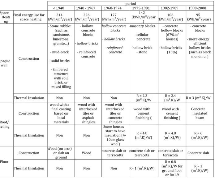
Simulations are carried out for the different construction periods and under different climates of France: Mediterranean, Oceanic, and Semi-Continental. Depending on the construction period, different window-to-wall ratios, wall, roof, and ground insulation thicknesses, air change rates, wall structures, etc. are considered. The envelope construction materials for the different construction periods are presented in Table 2 [25, 26, 27].
Table 2: Houses' construction in France during the different periods period
< 1948 1948 - 1967 1968-1974 1975-1981 1982-1989 1990-2000 Space
Heati ng
Final energy use for
space heating (kWh/m²/year) 214 (kWh/m²/year) 226 (kWh/m²/year) 177
142 (kWh/m²/year ) 106 (kWh/m²/year) (kWh/m²/year) 95 Opaque wall Construction - Stone rubble: (such as sandstone, limestone, granite…) - mud-brick - solid bricks - timbered structure with soil, brick, or mixed filling - hollow concrete blocks - hollow bricks - reinforced concrete -hollow concrete blocks - hollow bricks - reinforced concrete -masonry blocks -cellular concrete -hollow brick - stone - concrete hollow blocks (67% of houses) - hollow bricks (15%) - concrete blocks - more energy efficient hollow bricks (such as brick monomur)
Thermal Insulation Non Non Non (m².K)/W R = 2.3 (m².K)/W R = 2.4 R = 3 (m².K)/W
Roof/ ceiling Construction wood with a final coating based on local materials wood with interlocked tiles or asphalt shingles wood with interlocked tiles or concrete shingles wood with cement finishing ( wood with cement finishing ( Concrete insulated beam
Thermal Insulation Non Non
Some houses start to have insulation (4-10cm glass wool) R = 4.8 (m².K)/W) (m².K)/W) R = 4.8 (m².K)/W) R = 6 Floor
Construction Wood (on arcs) or slab on
ground Wood
concrete slab or
terracotta concrete slab or terracota concrete slab or terracota Concrete slab Thermal Insulation Non Non Non R= 1 (m².K)/W)
R = 0.8 (m².K)/W for ground floor or R=1.9 R = 3 (m².K)/W)
(m².K)/W for crawl spaces. Window Construction Simple glazed Simple glazed
Simple /
Double Simple / Double Simple / Double Simple then Double Window to wall
ratio 10 % 20 - 27% 37 % 25 % 25% 20%
4 Simulation Cases and Results
4.1 Envelope hygrothermal performance
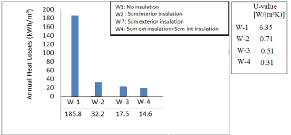
Three different concrete wall assemblies are considered.
1- un-insulated wall,
2- internally insulated wall with a traditional expanded polystyrene insulation (EPS)
3- externally insulated wall with the aeogel-based rendering (ABR)
4- internally insulated with polystyrene insulation and externally insulated with the
aerogel-based rendering
The simulations are carried out for Grenoble climate representative of a semi-continental French climate. The city of Grenoble was chosen as a simulation case because of its very specific climate: rain is more abundant, winter is colder, and summer is generally warmer than most of other cities in France. The nights are generally cooler (except during heat wave periods) and the afternoon is warmer than those in other main cities. The surrounding Alps Mountain forms a barrier preventing rain-filled clouds to move out while rainy westerly winds are trapped.
For the numerical simulation, the interior conditions were generated using the EN 15026 standard [28]. with a high moisture generation load. According to this standard, the indoor conditions are determined in relation to the exterior climate that provides an algorithm that determines the indoor climate taking outdoor conditions as a reference. The outdoor and indoor air temperatures and relative humidity over one year are shown in Fig. 3.
For each of the studied cases, the “North” orientation is chosen due to the lack of solar radiation that makes the wall cooler, and at the same time is subjected to a moisture load due to rain absorption. The simulation duration is 4 years to examine the drying effect of the walls over the years. The rain absorptivity is taken as 0.7 and the initial relative humidity in the wall assembly is taken as 80%.
Figure 4 shows the wall assembly water content for three cases: 5cm “Polystyrene” interior insulation, 5cm “Rendering” exterior insulation, and 5cm “Polystyrene” interior insulation with 5cm “rendering” exterior insulation. By placing interior insulation, the temperatures in the wall go low reducing the drying capacity of the wall leading to higher average moisture contents. For this wall, the average moisture content increases over the years meaning that it is unable to dry out throughout the years. On contrary, the presence of the aerogel-based rendering at the exterior façade allows the envelope to dry out where the yearly average moisture content within the assembly is decreasing throughout the years.
Figure 4: Evolution of the total water content over the 4 years for the different insulation configurations
Figure 5 shows the heat losses through the different wall structures. Compared to the un-insulated wall, all other walls achieve between 80% and 85% reductions in heat losses. Walls with the aerogel-based rendering have lower heat losses than walls with polystyrene. Comparing “W-2” (internally insulated wall with polystyrene) and “W-3” (externally insulated wall with aerogel render), the heat losses through W-3 is lower than that of W-2 by about 20%.
4.2 Whole building energy performance
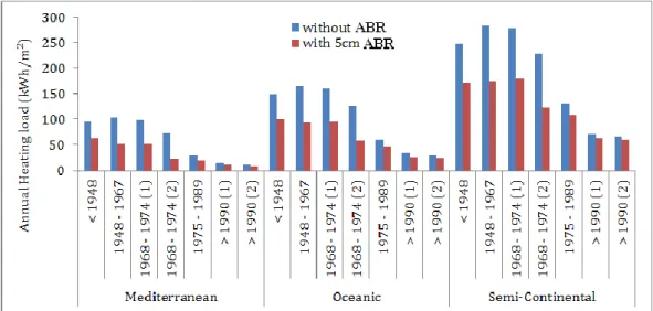
Figure 6 shows the house’s energy load without the ABC and with 5cm ABC on the exterior facades for the different construction periods and for the different climates. For the period 1968-1974, we modeled two different houses: the first one “1968-1974(1)” has simple glazed windows with no insulation in the roof; the second one “1968-1974(2)” has double glazed windows with 6cm thermal insulation in the roof. Also, for the period after 1990, we distinguish two cases: the first one, >1990(1), has the exterior walls composed of concrete structure with 10cm internal thermal insulation and the second one, >1990(2), has the exterior walls composed of 42cm of brick-monomur with no internal insulation.
Figure 6: Annual heating load for the different climates and the different construction periods with and without the rendering
From this figure, it is shown that for the old houses built before 1974, the percentages of energy reductions are between 40 – 68% for the Mediterranean climate, 37 – 55% for the oceanic climate, and 33 – 46% for the Semi-Continental climate. For the houses built in the period 1975-1989, the reductions are 32%, 23%, and 17% for the Mediterranean, Oceanic, and Semi-Continental climates. Lower reductions are achieved in the new houses, 23%, 14%, and 10% for the three climates, respectively. Since the new houses have already thermal insulation in the exterior envelope, adding the insulating rendering will not decrease a lot the annual load; however, this reduction is still needed to reach the low energy house thermal regulations.
We can conclude that this rendering is very interesting and beneficial for buildings under rehabilitation, especially the un-insulated houses, where a small thickness can reduce extensively the energy load, which also means conservation of the house’s livable area. For a medium level insulated house, adding the rendering also has a good advantage. For very well insulated houses, adding the rendering will still reduce the energy load, but certainly its importance lies in achieving more and more energy efficient houses to reach the new thermal regulations (French RT 2012) levels of the low energy buildings.
5 Conclusion
In this study, we present a recently developed insulating rendering based on silica-aerogels. It is mainly developed for exterior thermal insulation applications. In addition to new buildings, it can be
used for retrofitting existing ones since it has a high insulation performance and its application is easy, compatible with the traditional masonry facades, and using the ordinary well-known techniques. Numerical simulations are carried out using the software WUFI and EnergyPlus. Results show that adding the aerogel-based rendering on the exterior surface of the un-insulated or the already internally insulated walls reduces significantly or removes the moisture risks. It also reduces significantly the wall heat losses, and consequently the house’s energy consumption.
Acknowledgements
The authors gratefully acknowledge the supports of the partners of Parex.it Project: Parex Group, PCAS, CSTB, LOCIE, Wienerberger, and also the financial support of the French FUI fund and of Parex Group.
Reference
[1]
ADEME (French Environment and Energy Management Agency), 2014. Buildings. Retrieved from http://www2.ademe.fr/servlet/KBaseShow?sort=-1&cid=96&m=3&catid=12846 on May 2014.[2]
EEW (Energy Efficiency Watch), Final Report, 2013. Improving and implementing national energy efficiency strategies in the EU framework.[3]
Enkvist P.A., Naucler T., Rosander J. A cost curve for greenhouse gas reduction, The Mc Kinsey Quaterly, 2007[4]
Verbeeck G., Hens H. Energy savings in retrofitted dwellings: economically viable? Energy & Building – 2004[5] Koebel M., Rigaccci A., Achard P. Aerogels for Superinsulation: A synoptic view, Chapter 26, p 611, in “Aerogels Handbook (2011), editors: M. Aegerter, N. Leventis, and M. Koebel”.
[6]
Barbero S., Marco D., Ferrua C., and Pereno A. Analysis on existent thermal insulating plasters towards innovative applications: Evaluation methodology for a real cost-performance comparison. Energy and Buildings 77 (2014), 40-47.[7] Achard P., Rigacci A., Echantillac T., Bellet A., Aulagnier M., Daubresse A. Enduit isolant à base de xerogel de silice. WIPO Patent WO/083174, 2011.
[8]
Ibrahim M., Biwole P.H., Wurtz E., Achard P. A Study on the Thermal Performance of Exterior Walls Covered with a Recently Patented Silica-Aerogel-Based Insulating Coating. Building and Environment 81 (2014) 112-122.[9] Ibrahim M., Achard P., Wurtz E., Biwolé P. Optimizing insulation-thermal mass wall layer distribution from maximum time lag and minimum decrement factor point of view. In Proceedings of BS (2013): 13th Conference of the International Building Performance Simulation Association [10] NF EN 12667. Thermal performance of building materials and products - Determination of
thermal resistance by means of guarded hot plate and heat flow meter methods - Products of high and medium thermal resistance.
[11] NF EN 1159-3. Advanced technical ceramics - Ceramic composites, thermophysical properties - Part 3: determination of specific heat capacity.
[12] NF EN 1602 standard. Thermal insulating products for building applications - Determination of the apparent density.
[13] NF EN ISO 12572. Performance hygrothermique des matériaux et produits pour le bâtiment - Détermination des propriétés de transmission de la vapeur d'eau
[14] Kistler, S.S. Coherent expanded aerogels. Journal of Physical Chemistry 36(1931) 52–64 [15] Ibrahim M., Biwole P.H., Wurtz E., Achard P. Limiting windows offset thermal bridge losses
using a new insulating coating. Applied Energy 123 (2014) 220-23
[16] IBP. 2011. WUFI® Pro version 5.1. Holzkirchen, Germany: Fraunhofer Institute for Building
Physics. http://www.WUFI. de/index_e.html. (15 January 2013).
[17] Targo Kalamees, Juha Vinha. Hygrothermal calculations and laboratory tests on timber-framed wall structures. Building and Environment 38 (2003) 689–697
[18] Mantha, P., & Arena, L. B. (2012). A Systematic Approach to Hygrothermal Modeling and Compliance With Failure Criteria Using WUFI®.5th National Conference of IBPSA-USA, Madison, Wisconsin, August 2012
[19] J. Delgado, N. Ramos, E. Barreira, V. de Freitas. A critical review of hygrothermal models used in porous building materials. Journal of Porous Media, 13 (2010), pp. 221–234
[20] D. Allinson, M. Hall. Hygrothermal analysis of a stabilized rammed earth test building in the UK. Energy and Buildings, 42 (2010), pp. 845–852
[21] F. Antretter, F. Sauer, T. Schopfer, A. Holm. Validation of a hygrothermal whole building simulation software Proc. of Building Simulation 2011, 12th Conference of International Building Performance Simulation Association, Sydney, (2011) 1694–1701
[22] ANSI/ASHRAE 140. Standard Method of Test for the Evaluation of Building Energy Analysis Computer Programs, 2007
[23] VDI Richtlinie 6020. 2001. Anforderung an Rechenverfahren zur Gebäude- und Anlagensimulation. Düsseldorf, Berlin: VDI-Verlag GmbH.
[24] EnergyPlus v. 7.0.0. US Department of Energy. Energy Efficiency and Renewable Energy Office, Building Technology Program, 2011. http://apps1.eere.energy.gov/buildings/energyplus/. [25] Analyse Détaillée du Parc Résidentiel Existant, Report 2009,
www.reglesdelart-grenelle-environnement-2012.fr.
[26] Etude socio-technico-économique du gisement de travaux de rénovation énergétique dans le secteur immobilier résidentiel – Outil de modélisation énergétique territoriale ENERTER. Direction de l'habitat, de l'urbanisme et des paysages (DHUP) 2011
[27] Typologie des bâtiments d’habitation existant en France. Direction de l'habitat, de l'urbanisme et des paysages (DHUP) 2007.
[28] EN Standard 15251. Indoor environmental input parameters for design and assessment of energy performance of buildings addressing indoor air quality, thermal environment, lighting and acoustics, 2007.
![Table 2: Thermal conductivity of some traditional insulation products [14]](https://thumb-eu.123doks.com/thumbv2/123doknet/13320000.399744/5.892.185.711.256.406/table-thermal-conductivity-traditional-insulation-products.webp)