Publisher’s version / Version de l'éditeur:
ASHRAE Handbook 1977, Fundamentals Volume, Chapter 22, pp. 22.1-22.28,
1978-12-01
READ THESE TERMS AND CONDITIONS CAREFULLY BEFORE USING THIS WEBSITE. https://nrc-publications.canada.ca/eng/copyright
Vous avez des questions? Nous pouvons vous aider. Pour communiquer directement avec un auteur, consultez la première page de la revue dans laquelle son article a été publié afin de trouver ses coordonnées. Si vous n’arrivez pas à les repérer, communiquez avec nous à [email protected].
Questions? Contact the NRC Publications Archive team at
[email protected]. If you wish to email the authors directly, please see the first page of the publication for their contact information.
NRC Publications Archive
Archives des publications du CNRC
Access and use of this website and the material on it are subject to the Terms and Conditions set forth at
Design heat transmission coefficients
https://publications-cnrc.canada.ca/fra/droits
L’accès à ce site Web et l’utilisation de son contenu sont assujettis aux conditions présentées dans le site
LISEZ CES CONDITIONS ATTENTIVEMENT AVANT D’UTILISER CE SITE WEB.
NRC Publications Record / Notice d'Archives des publications de CNRC:
https://nrc-publications.canada.ca/eng/view/object/?id=aa556e42-82fe-41c0-ad4c-adb711df9e37
https://publications-cnrc.canada.ca/fra/voir/objet/?id=aa556e42-82fe-41c0-ad4c-adb711df9e37
National Flesearch
Counci!Canada
Conseilnational
de recherches Cana&,
DE$IGTS
F{HAT
TRANSfuIISSICN
COHFFICEENTS
CHAPTHR
28, ASHRAE
I{ANDtsOOK
1977
FUNDAMEruTALS
VOLUfI{E
,.1{
t l-YZgD
Reprirrted with perrnission of the
Arnerican Society of Heating, Refriger:ufi.ng
and Air'Conditioning Bngineers.
Technical Paper No. 168
of the
Division of Building Research
i : , : . _ ' , i l j . i ' . . r
#' ';::'',t:ic -
PREFACE
There is a continuing requireinent in the work of architects,
engineers, and others concerned with heating, ventilating,
and
air-conditioning
of buildings
for tabulated information
on the heat
t r a n s m i s s i o n c o e f f i c i e n t s
o f b u i l d i n g m a t e r i a l s a n d b u i l d i n g s e c t i o n s .
The ASHRAE Handbook 1977 Fundamentals Volume is the most authoritative
and the nost widely used reference source in this connection.
The
Division
is indebted to the Society for perrnission to reproduce
Chapter 22 in full
for the assistance and convenience of Canadians
requiring
such infornation.
Chapter 22 is based upon the best information
available
and is kept
up to date through frequent revisions.
It is applicable
to Canadian as
well as to United States conditions and it is recommended for use in the
estimation of heating and cooling loads and in other heat transfer
problems in buildings.
Any reservations
to be observed in its use are
given in the text and in the footnotes to the various tables.
It is
inpossible
to guarantee that the values given will
apply to a particular
product.
They are considered to be the most representative
values that
can be established
for use in design.
For conductivity
of a particular
product the user may obtain the value suppl ied by the manufacturer or
s e c u r e t h e r e s r r J t s o f r - r n b i a s e d te s t s .
As this ASHME Chapter is frequently
revised,
successive printings
as a DBR paper can be based on the most recent version.
Chapter 9 of
the 1960 ASHRAE
Guide and Data Book (as it was then called) was first
used to replace a DBR conpilation
issued in 1951 as DBR Technical Paper
N o . 7 .
I t i n t u r n w a s r e p l a c e d b y t h e 1 9 6 3 r e v i s i o n w h i c h w a s i s s u e d a s
Technical Paper 168 in view of the change in Chapter title
and replaced
again by the 1965 version.
This present reprint,
from the 1977
Fundamentals Handbook, is the nost up-to-date information on this subject.
0ttawa
Novenber 1978
C . B . C r a w f o r d
Director
CHAPTER 22
DESTGN HEAT TRANSMISSION COEFFICIENTS
Heal Transfer Detinitions and Symbols; Surface Conductance; Calculating Overoll Coefficients; Overall Coefficientsand Their Practical Use; Insulating Constructions; Adjustment for Fralning; Curtain lYoils; Ventilated Attics; Foundalion Coefficiena; Gloss'and Door Coefficients; Wind Effects; Heat Loss Due to Infiltration; Calculating Surface Temperatures; Conductivity of Indu.strial Insulotions; Bare Surface Heal Losses; Heat Flow Calculations;
Buried Pipe Lines: Thermal Charocteristics ond Response Factorsfor Floors, Walls, and Roofs
rn HE design of a heating, refrigerating, or air-conditioning -[ system, including selection of building insulation, sizing of piping and ducts, or evaluation of thermal performance of system parts is based on the principles of heat transfer given in Chapter 2. The equations most widely used to estimate heat transfer loads chargeable to the various parts will usually determine the heat transfer rate under steady state conditions. For a eiven part under standard conditions, this rate is a specific vafue, U, the overall coeflicient of heat transmission or thermal transmittance.
This chapter is concerned with the concepts and procedures for determining such coefficients, and includes a brief discussion of factors that may affect the values of these coef-ficients and performance of thermal insulations. Coefficients may be determined by testing, or computed from known values of thermal conductance of the various components. Procedures for calculating coeflficients are illustrated by examples and, because it is impracticable to test all com-binations of materials, tables of computed design values for the more common constructions are given.
Units in this chapter are in the customary (i.e., U.S., E - ^ l : - | . ^ - l ^ - - \ t - . L - r - l l ^ - - , : - - l - c : - - ' . : - . . . - a t . , - i i E , i i s r r , a a i u L E J , , J y ) . r r r i ) . l r r r r r ! r u r r u w l r r t , u g t i r t r t t u l l s u t f l t r d t transfer, the customary unit, followed by the SI unit, is given. Note that although the SI unit of temperature is the kelvin (K), the degree Celsius (formerly centigrade) is properly used with SI units. The temperature interval one degree Celsius equals one kelvin exactly. Factors for converting to SI are given in Table l8 and in Chapter 35.
HEAT TRANSFER DEFINITIONS AND SYMBOLS e = thermal lronsmission or rate of heat flow: the quantity of heat flowing due to all mechanisms in unit time under the conditions prevailing at that time; in Btu/hr or (W).
Nore: Mechanisms relate to modes of heat transfer by solid eon-duction, mass transfer, gas conduction, convection, and radiation. These may occur separately or in combination, partially or rolnliy depend ing upon specific circumstances.
rt or I = thermal conductivity: the tFermal transmisri: -:, by conduction only, in unit time through unit area of ar. . :-finite slab in a direction perpendicular to the surface, \A it.;!l unit difference in temperature is established between the sur-faces; in (Btu . in.)/(hr . ft2 . F) or W/(m . K).
Nole I: A body is considered homogeneous wherr the above propcr-ty is lound by measurement to be independent of sample dimcnsions. Nole 2i The property nrust be identified with a specific mean rem-perature, which varies with temperature'. and a direction and orien-tation of thermal transmission, since sonre bodics are not isotropic with respect to the property.
Note 3: F'or many therrnal insulation materials, thermal trans-mission occurs by a combination of modes of heat transfer. The measured property should be referred to as an effectivr. or apparent thernral conducrivity for the specific tcst conditions (sample thickncss and orientation, environment, environrncntal pressurc, and tem-perature difference).
r or w = thermol resistivity; the reciprocal of thermal con-ductivity;1hr . ft2 . F)/(Btu . in.) or (m . K)/W.
C = thermal conductance; the thermal transmission in unit time through unit area of a particular body or assembly having defined surfaces, when unit average temperalure dif-ference is established between the surfaces; Btu/(hr . ft2 . F) o r W / ( m 2 . K ) .
Note It The average temperature of a surface is one that adequately approximates that obtained by integrating the tcmperature over the body.
Note 2: When the two defined surfaces of a mass-type thermal in-sulation are not of equal areas, as in the case of thermal transmission in a radial direction (see Chapter 2, Table 2), or are not of uniform separation (thickness), an appropriate averag,e area and averag,c thickness must be given.
Note 3: When heat transler is by conduction alone, the average thermal conductivity is the product of the thermal conductance per unit area and the thickness. The average thermal resistivity is the reciprocal of the average thermal conductivity. When conduction is supplemented by any or all of the other modes of hcat transfer, the ap-parent or efJective thermal conductivity is obtained by multiplying the thermal conductance by the thickness. Thc apparent or effective resistivity is the reciprocal of thc apparenr or effecrive therrnal conductivity.
ir;ole 4: Where there rs alr passage through the body, the effectire thermal conductance (resistance) must include details of the pressure difference across the body. For a body which is transparent to light, the effective thermal conductance (resistance) may include fenestration, but the optical properties or shading coefficient of the body must be given.
Note 5: The thermal conductance of some bodies is related to their thickness. In such cases, the apparent thernral conductivity is a I'unc-tion of thickness. For this reason, it is preferable to express results as effective thermal conductances (resistances) rather than eifective ther-mal conductivities (resistivities).
Note 6: "Total" and "areal" lhermal conduclance are often uscd as synonyms for thermal cotrductance.
Nole 7: Values of thermal conductance {referred to as cor-duclances) and their inverses (resislances\ of the more common building matcrials are tabulated later in this chapter.
R : thermal resistance; the reciprocal of thermal con-ductance; (hr . ft2 . F)/Btu or (rn2 . K)/W.
U: thermal transmittance; the thermal transmission in unit time through unit area of a particular body or assembly, including its boundary films, divided by the difference be-tween the environmental temperatures on either side of the body or assembly; Btu/(hr ' ft2 . F) or W,z(m2 . K).
Note l: This is often relerred to as the overall coefficient ol heal transfer.
Note 2: In practice, the fluid is air, the boundary film is rhin, and the average tempcralure of the fluid is tlrat obtained by averaging over a finite rcgion ol the fluid near this film.
fi = film or surface conductance: the thermal transmission in unit time to or from unit area of a surface in contact with its surroundings for unit difference between the temperature of the surface and the environmental fluid temperature; B t u / ( h r . f t 2 . F ) o r W / ( m 2 . K ) .
Note ,f : Tlrc surroundings must involve air or other fluids for radia-tion and convccrion to take place.
Thc preparation of this chapler is arsigncd to TC 4.4, Insularion and Moisturc Barrietl
22.2
CHAPTER 22
Norc 2i Subscripls i and o are often used to denote inside andout-side su r face conductances, respectively.
e = emiltance; the ratio of the radiant flux emitted by a specimen to that emitted by a blackbody at the same temperature.
Note: The combined effect of the surface emittances of boundary surfaces of an air space where lhe boundaries are assumed to be
parallel and of large dimensions, as compared to the distance between s ihem, is often referred to as efJective emittance (E). Values for a range : ofair spaces and conditions are tabulated later in this chapter. ! e: surface rcfkctunce; the ratio of the radiant flux . i rcflected by an opaque surface to that falling upon it; dimen- ;
sionless.
E
SURFACE CONDUCTANCE
The convectiofl part of surface conductance is affected by air mov€ment. Fig, I shows results of testsr made on l2-in.
square samples of different materials at a mean temperature
of 20 F for wind velocities up to 40 mph. These conductances
include the radiation portion of the coefficient which, for the test conditions, was about 0.7 Btu/(hr . ft2 . F). More recent tests2 on s -ooth surfaces show surface length also signifi-cantly affects the convection part of conductance; the average value decreases as surface length increases. Moreover, obser-vations3 of the rnagnitude of low temperature radiant energy received from outdoor surroundings show that only under certain condtions may the outdoors be treated as a blackbody radiating at air tcmperature.
CALCUL{.TING OVERALL COEFFICIENTS
Using the principles of heat transfer in Chapter 2, it is possible to calculate overall coefficients with the resistance method. The total reistance to heat flow through a flat ceiling, floor, or wall (or a curved surface if the curvature is small) is eoua! numeriqnllrr 14 the surn of the resistatces ig series.
R 7 = R , * R r * R 3 + R 4 + . . . + R n ( l )
where R1, R2, Gtc., are the individual resistances of the wall components, and Rl is total resistance.
For a wall of a single homogeneous material of conductivity k and thickness,L with surface coefficients l, and ho:
1977
Fundamentsls
Handbook
Fig. I Surface Conductance for Different l2-in.
Sluare Surfaces as Affected by Air Movementr
where ti and lo are the indoor and outdoor temperatures, respectively.
Hence, the temperature at the interface between Rr and Rt is:
t p 2 : t i - A t , ( 5 )
For types of building materials having nonuniform or ir-regular sections such as hollow clay tile or concrete blocks, it is necessary to uselhe conductance C of the section unit as manufactured. The resistance R of the section l,/C would be used as one of r,he reslstances in en equ3ticn si:n!!ar to Eq 2 a n d 3 .
Note that in order to compute the U-value of a construc-tion, it is first necessary to know the conductivity and thickness of homogeneous materials, conductance of
nonhomogeneous materials (such as concrete blocks), surface
conductances of both sides of the construction, and
con-ductances of any air spaces or the thermal resistances of in-{ividual elements.
If the conductivities of materials in a wall are highly
depen-dent on temperature, the mean temperature must be known to
assign the correct value. In such cases, it is perhaps most con-venient to use a trial and error procedure for the calculation of the total resistance, R7. First, the mean operating temperature for each layer is estimated and conductivities k or conductances C selected. The total resistance Rr is then calculated as in Eq 3 and then the temperature at each inter-face is calculated from Eq 4 and 5.
The mean temperature of each component (arithmetic mean
of its surface temperatures) can then be used to obtain con-ductivities k or conductances C. For nonlinear relationships, see Chapter 19, Fig. 2. This procedure can then be repeated until the conductivities or conductances have been correctly selected for the resulting mean temperatures. Generally, this can be done in two or three trial calculations.
Series and Parallel ltreat Flow Paths
In many installations, components are arranged so that parallel heat flow paths of different conductances result' If there is no lateral heat flow between paths, each path may be considered to extend from inside to outside, and
trans-mittance of each path may be calculated using Eq I or 3' The
average transmittance is then:
^ ' =
;
* * *
(2'
Ih
l - *t-*l
C k 2 h o Then, by definition: U = l / R rFor a wall with air space construction, consisting of two homogeneous materials of conductivities k' and k2 and thicknesses L, and /.2, respectively, separated by an air space
ofconductance C:
n , = I + L ] +
- n i K r and(3)
U = l / R r
The temperature at any interface can be calculated, since
the temperature drop through any component of the wall is
proportional to its resistance. Thus, the temperature drop Al1 t h r o u g h R l i n E q l i s :
Design
Heat Transmission
Coefficients
U6"t = a(U") + b(U) +...+ n(U,l (6) where a, b," ',n are respective fractions of a typical basic area composed of several different paths whose trans-mittances are Uo. Uo,- Un.
If heat can flow laterally in any continuous layer so that transverse isothermal planes result, total average resistance Rn"", will be the sum of the resistances of the layers between such planes, each layer being calculated by the appropriate Eq
I or a modification of Eq 6, using the resistance values. This is a series combination of layers, of which one (or more) pro-vides parallel paths.
The calculated transmittance, assuming parallel heat flow only, is usually considerably lower than that calculated with the assumption of combined series-parallel heat flow. The ac-tual transmittance will be some value between the two calculated values. In the absence of test values for the com-bination, an intermediate value should be used; examination of the construction will usually reveal whether a value closer to the higher or lower calculated value should be used. Generally, if the construction contains any highly conducting layer in which lateral conduction is very high compared to transmittance through the wall, a value closer to the series parallel calculation should be used. If, however, there is no Iayer of high lateral conductance, a value closer to the parallel heat flow calculation should be used, as illustrated in Example I .
Exomple I: Consider a construction consisting of: l. Insidesurface having film coefficient ft, = 2. 2. Acontinuouslayerof material of resistanceRr = l.
3. A parallcl combination containing two heat flow paths of pro-portionate areas, a = 0.1, and b : 0.9, with resistances Ro, = I and Raz : 8'
4. A continuous layer of material of resistance Rt = 0.5. 5. Ouisidesur izrcc i'a"irrg iiirir vociiiciciri ii o - 1.
Solution: lf parallel heat flow paths are assumed from air to air, the total resistance through area a will be:
R o 7 = l / h , + R r + R o z + R t + l / h o = 0 . 5 + I + I + 0 . 5 + 0 . 2 5 = 3 . 2 5 and
U o = l / R o 7 = l / 3 . 2 5
The resistance and transmittance through area D will be: R 6 7 = l / h ; + R l + R b 2 + R ! + l / h o
= 0 . 5 + I + E + 0 . 5 + 0 . 2 5 = 1 0 . 2 5 and
U 6 = l / R 6 7 = l / 1 0 ' 2 5
Then the average calculated transmittances will be:
I ) 1 a 1 = a ( I r o t +
b ( u ) =
#
- + ;
: o . l t e
lf, however, isothermal planes are assunted to occur at both surfaces o f R r and of R, , the total calculated resistance w i l l b e :
( R o 2 ) ( R p 2 )
+ R 1 + l / h n R 7 = l / h ; + R r +
i R o r * b n o , (E"zXflz)
= combined resistanceof R o2andR62 = 4.71 aR6r*bRo2
22.3
T l h e n , R 1 = 0 . 5 + t + 4 . 7 1 + 0 . . 5 + 0 . 2 5 = 6 . 9 6 arid Ui^", = l/6.96 = O.lM
If ltr and Rl ar€ values for homogeneous materials, a value of about 0.125 might be selected; whereas, if they contain a highly con-ductinglayer. a valueof 0.135 might beselected.
When the construction contains on€ or more paths of small area having a high conductance compared to the conductance of the remaining area, the following method is suggested. Heat Flow Through Panels Contair;ing Metal
The transmittance of a panel which rrcludes metal or other highly conductive material extending w holly or partly through insuiation should, if possible, be determined by test in the grrarded hot box. When a calculation is requiredt a good ap-proximation can be made by a Zone Melhod. This involves two separate computations-one for a chosen limited portion, Zone A, containing the highly conductive element; the other for the remaining portion of simpler construction, called Zone B. The two computations are then combined, and the average transmittance per unit of overali area is calculated. The basic laws of heat transfer are applied, by adding area conductances C'A of elements in parallel, and ailding area resistances R' A of elements in series.
The surface shape of Zone.,4 is determined by the metal ele-ment. For a metal beam (Fig. 2 and 3), the Zane A surface is a strip of width L|z, centered on the beam. For a rod perpen-dicular to panel surfaces, it is a circle of diameter W. The value of I/is calculated from Eq 7, which is empirical.
W : m + 2 d
where
m = width or diameter of the metal heat path terminal, in-ches.
t/ - tiistaiice iroiii liaiiei surface io iiieiai, irtuiies. TIic valus of d should not be taken less than 0.5 in. (for still air). In general, the value of I/ should be calculated by Eq 7 for
BAS|C aREA: 2 sQ rI ---l I I I I I ZONE A t l t l ? O N E r l l l l t i l ZONE B 2-A N TLEVAT ION
For enlargcd sectlon of Zone A, see Fi8. 3
Fig. 2 Gypsum Roof Deck on Bulb Tees
FOOFING o 0 3 0 2 (7) GYPSUM CONCRETE o 0 3 0 2 S T f E L SULB TfE G L A S S ' I B E R I N S U L A . I I O N . { r o o 5 a o z i o - - w:3 s/s ---1r1r"---t, s6a- tt1,
Fig. 3 Enlarged Section of Zone A of Fig. 2 SECT STEEL NON - STEEL
N O A R € A A R E A SQ FT SQ FT o 6 : o : d ' . 1 3 6 o o l . o o . o d o b o o-t . ' o o . ; I o o o , d o o ' 0 ' o r . ' . l 6 _"_:_l o _. l . g t
h,l.
F m 1 ' . . 4 0 0 r o o ? 9 222.4
CHAPTER 22
1977 Fundamentsls
Handbook
each end of the metal heat path, and the larger value, within the limits of the basic area, should be used as illustrated in Ex-'
omple 2.
Example 2: Calculate transmittance of the roof deck shown in Fig. 2 ' and 3. Tee-bars on 24-in. centers support glass fiber form boards, gyp-sum concrete, and built-up roofing. Conductivities of components are: steel 312: gypsum concrete 1.66; glass fiber 0.25. Conductance of built-up roofing is 3.0.
'
Solution: The basic area is 2 ft2 (24 in.xl2 in.), with a tee-bar (12 in. long) across the middle. This area is divided into Zons A and B.
Zone A is determined from Eq ? as follows:
TopSide W = m I 2d = 0.625 + 2 x 1.5 * 3.525 in. BottomSide W = m * 2d = 2.0 + 2 x 0.5 = 3.0in.
Using the larger value of W, the ar ea of Zane A is (12 -x 3.625) / | U = 0.30tft2. The ar ea of Zone B is 2.0 = 0.302 = I .698 ft2.
To determine area transmittance for Zone.4, the structure within the zone is divided into five sections parallel to the top and bottom surfaces as shown in Fig. 3. The area conductance C' A of each section is calculated by adding the area conductances of its metal and nonmetal paths. Area conduclances of the sections are con-verted to area resistances l/(R . Al and added, to obtain total rcsistance of Zone A .
Caution
A panel with internal metallic structure, bonded on one or both sides to a metal skin or covering, presents special prob-lems of lateral heat flow not covered in the foregoing Zone Method.
Series Heat Flow through Unequal Areas
A consFuction may be made up of two or more layers (flat or of small curvature) of unequal area, separated by an air space and arranged so that heat flows through the layers in series. The most common such constructio:i is a ceiling and roof combination where the attic space is unheated and unventilated. A combined coefficient based on the most con-venient area from air inside to air outside can be calculated from Eq 8.
r
|
* *...+ _+
(8)
R' =
d,
*
,u,
*
,ru,
nou,
The combined coefficient U is the reciprocal of R7, or U = l / R 7
where
U = combined coefficient to be used with.4 ' . Rr = total resistance to all elements in series. U t, U2,...,Up = coefficient of transmission of .d 1,
Az,' ' ',Ar, resPectivelY.
frz, frt,' ' ' ,np = area ratios d2 /At, Ar/At,' ' ' , Ap/At, respectivelY.
Note that the overall coefficient should be multiplied by the arca A1 to determine the heat loss. Values of Uy. U2. Ur.' ' ', U, should be calculated using Eq l, 2, or 3; if any layer con-tains parallel heat flow paths (i.e., windows or <lorm-ers on roofs), Eq 6 may be used.
In the calculation, the resistance of the air spaces between layers should be accounted for by assigning one-half of an ap-propriate air space resistance to each of the layers, rather than the conductance of the surface.
U, Concept
In section 4.0 of ASHRAE Stondord 9O-75, Energy Con-semalion in New Building Design, requirements are stated in terms of Uo, where Uo is the combined thermal transmittance ofthe respective areas ofgross exterior wall, roof/ceiling, and floor assemblies. The U" equation for a wall is as follows:
,, - U*oilA.ott* U*iraon'4window* Ua*Aaoo,
^ " where
Uo = the average thermal transnlittance of the gross wall area, Btu/h . ft2 . F
Ao = the gross area of exterior walls, ft2 (m2) U,ot! = the thermal transmittance of all elements of the
opaque wall area, Btu/h ' ft2 'F A,ort = oPaque wall area, ft2
U*indow = the thermal transmittance of the window area, B t u / h . f t 2 . F
A vindo* = window area (including sash) ft2
Udoor= the thermal transmittance of the door area, B t u / h . f t 2 . F
Ud*, = door area, ft2
NOTE: Where more than one lype of wall, window and/or Section Area x Conduclrnce
r/(c . Al
C . A = R / A Air (outside, l5 . m p h ) No. I, Roofing No.2, Gypsum concrete No. 3, Steel No. 3, Gypsum concrele No.4, Steel No.4, Glass fiber No. 5, Steel Air (inside) 0.302 x 6.0 0.302 x 3.0 0.302 x 1.66/1.125 0.052 x 312.0/0.623 0.250 x 1.66/0.625 0.01(x x 312./1.00 0.292 x 0.25/1.00 0.167 x 312/0.125 0.302 x 1.63 1.8 t2 0.552 0.906 r.104 0.446 2.242'3.U )o'o3E
3'24 )0.302 0.073 416.83 0.002 0.492 2.031 TolalR/A = 6.271 Area transmiuanceof Zone A = l(R/A') = 1/6.271 = 0.159. For Zone B, the unit resistances are added and then converted to area transmittance, as shown in the following table.Secllon Resistrnce.f Air (outside, 15 mph) Rooting Gypsum concrete Glass fiber Air (inside) Total resistance = 6.167 Unit transmittance = l/R = 0.162 Area transmittance U.A
f o r Z o n e B = 1.698x0.162 * 0 . 2 7 5
for ZoneA 0.159
Total area transmittance of Dasrb area = O.434 Transmittance per ft2 = 0.414/2.0 = O.2l'7
In tests on similar constructionr made by the guarded hot-box method, one laboratory reported a U-value of 0.219 Btu/(hr . ft2 .'F), and another laboratory reported a u-value of 0.206Btu/(hr . ft2 . F).
When the steel is a large proportion of the heat path, as in Example 2, detailed calculations of resistance in sections 3,4, and 5 of Zone A are not justified. If only the steel were con-sidered, the final result of Example 2 would be unchanged.
If the steel path is small, as for a tie rod, detailed calcula-tions for section 3, 4, and 5 are necessary (see Table 4H).
l / 6 . 0 : 0 . 1 6 7 l / t . O : 0.333 r . 1 S / t . 6 : 1 . 0 5 4 t.O0/0.25 = 4.000 l / 1 . 6 3 = 0.613
Design Heat Transmission
Coefficients
door is used, the U x A term for that exposure shall be ex-panded into ils sub-elements, os:
UvottlA.ol\ I U.at2 A*o4'EIc'
OVERALL COEFFICIENTS A N D THEIR PRACTICALUSE
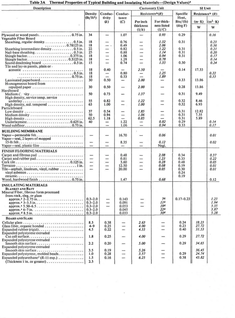
The values in Tables 1,2,2C,3A, and 38 for component elements and materials were selected by ASHRAE Technical Cornmittee 4.4, as representative, They are based on available published data obtained by the guarded hot plate method (ASTM Cl77), heat flow meter method ASTM C5l8), or by the guarded hot box method ({STM C236). Because of variations in commercially available materials of the same type, not all of these selected represeiltative values will be in exact agreement with data for individual products. The value for a particular manufacturer's material can be secured from unbiased tests or from guaranteed manufacturer's data.
The most exact method of determining the heat trans-mission coefficieint for a given combination of building materirls assenrbled as a building section is to test a representative section in a guarded hot box. However, it is not practicable to test all the combinations of interest. Experience has indicated that U-values for many constructions, when calculated by the methods given in this chapter, using accurate values for component materials, and with corrections for framing member heat loss, are in good agreement with the values determined by guarded hot box measurements, when there are no free air cavities within the construction.
Simplified Procedure for Deterrnining U- Values
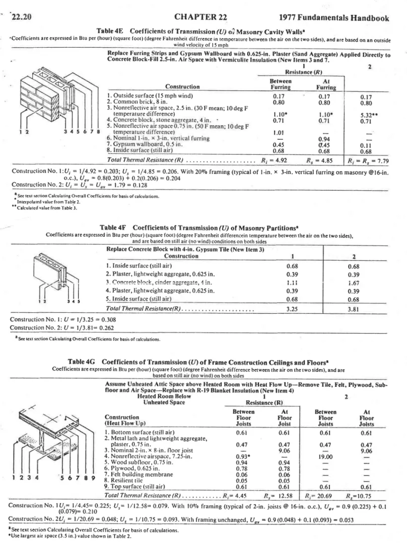
Tables 4^A through 4K illustrate the procedure which enables the engineer to determine and compare values for many types of construction. To determine the U- value for . . - : - - . . 1 ^ . - J ^ ^ - - . - . . ^ . : ^ - ! . - ^ r - L l - ^ , a . L - ^ . - ^ L , r , f L -a i i i l i i S r i r -a -a e u t v r r ) r r ( r L r t v r r , i t J ! l d v r ! ) t n t r r r v u S l l { 4 . I l t E benefit derived from addition of insulation materials is shown in Tables 5A and 58. The average U-value is then determined by Eq 9. Additional summer values for ventilated and nonventilated attics are given in Table 6.
This simplified procedure provides a means of evaluating economic considerations involved in selection of insulating material, as adapted to various building constructions.
Special attention must be given to vapor barriers, outlined in Chapters 19 and 20. Moisture from condensation or other sources reduces the heat flow resistance of insulation'
Values Used in Calculation of U-Value Tables
Tables 4A through 4K are based on values given in Tables 1,2., and 3,{. The following conditions have been used to calculate the U-value by including framing members or other areas of through conduction.
Equilibrium or steady state heat transfer, eliminating effects of heat capacity.
Surrounding surfaces at ambient air temperatures.
Exterior wind velocity of l5 mph for winter (surfacerR = 0.17) and 7.5 mph for summer (surface R : 0.25).
Surface emittance of ordinary building matcrials c = 0.90. Eq 9 is used to corrcct for the effect of framing members.
+" = ,fitu,r*(t-
,fi)tu,,
where
Uo" = average Uvalue for building section. Ut = Uvalue for area between framing members.
22.5
U, = lJ vaiue for arca backed by framing members.g = percentage of area backed by framing members.
For those systems with complicated geometry, Uo" should be measured by laboratory tests on a large, representative area of the building section including the framing system.
Exanple 3: Parallel heat flow through framing (studs, joists, plates, furring, etc.) and insulated areas is calculatcd by Eq 9. Consider a frame wall with R-l I insulation, a Ur-value across the insulated space of 0.069 (ft = l . 3), and a U"-value across the framing of 0.128 (R = ?.81). Assuming a 2090 framing (typlcal for lGin. in o.c. fram-ing includfram-ing multiple studs, plates, headers, sitls, band joists, etc.), the average U-value of this wall can bc calculated.
Ui = 0.069; Us =0.128; S = 20
IJ ," : (a.21 (0. I 28) + (0.8) (0.069) : 0.026 + 0.055 = 0.081 For a frame wall with 24-in. o.c. stud space, the framing factor is estimated at 1590. In this case, thi average U-value betomes 0.078. Depending on the care and installation of the insulation, U-values ob-tained in practice may be higher than those calculated here.
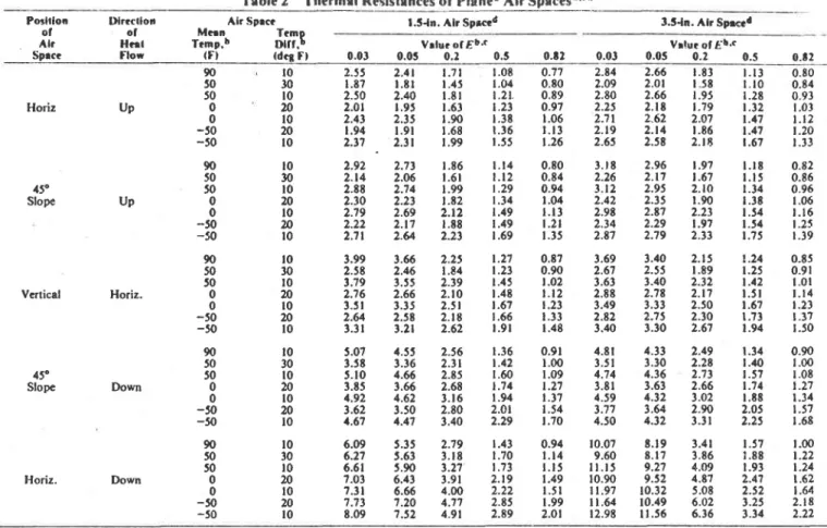
ln construction involving air spaces, the U-values shown are calculated for areas between framing. See examples in Table 4 if an allowance is to be nrade for this effect.
To condense the tables, an average resistance value (avg R) has been used in some tables for types of materials having approximately the same thermal resistance values. The difference between the average value and the exact value for any given material usually causes no significant change in the resulting U-value.
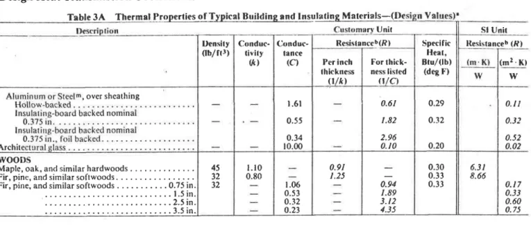
Actual thicknesses oJ lumber assumed to be as follows:
Nominal Aclual Nominal Actual
I in. (S-2-S) . .0.75 in. 3 in. (S-2-S). . . 2.5 in. l . 5 i n . ( S - 2 - S ) . . . 1 . 2 5 i n . 4 i n . ( S - 2 - S ) . . . 3 . 5 i n . 2 in. (S-2-S). . . 1.5 in. Finish flooring
2 . 5 i n . ( S - 2 - S ) . . . 2 i n . ( m a p l e o r o a k ) . . . 0 . 7 5 i n . Note that the effects of poor workmanship in construction and in-stallation have an increasingly greater percentage effect on heat trans-mission as the U-value becomes numerically smaller. Failure to meet design estimates may be caused by lack of attention to exact com-pliance with specifications. A factor of safety may be employed as a precaution when desirable.
Caution
Although the validity of calculating U-values for all the types of constructions in Tables 4A through 4K' 5A' 5B' 6' and 7 has not been fully demonstrated, calculated values are given because measured values are not available'a It is em-phasized that the calculated values in Tables 3A' 3B' 4A through 4K, 5, and 6 are given for the convenience of the reader.
In calculating U-values, exemplary conditions of com-ponents and installations are assumed (i.e., that insulating materials are uniformly of the norninal thickness and con-ductivity, air spaces are of uniform thickness and suriace temperatures, effects due to moisture are not involved, and installation details are in accordance with design). Some ev!-dence of departures of measured from calculated values for certain insulated constructions is given in Building lv{aterials and Structures Report BMS l5l, National Bureau of Stan-dards. To provide a factor of safety to account for departures of constructions ft'oru requirements and practices' some lnay wish to moderately increase the calculated U-values of the in-sulated walls, floors, and ceiling sections obtained from Tables 4A through 4K before making adjustments for fram-ing (at indicated in Eq 9). Where reflective air spaces are in-volved in builcling construction, and their thermal resistance values constitute a niajor share of the installed resistance of the insulation, increases of U-values up to l09o for applica-tions where heat flow is horizontal or upward, and up fi ZAs/o
(e)
where heat flow is downward, appear reasonable, on the basis
of present information, However, to accurately determine
. thermal resistance values of multiple air spaces, tests on the actual construcrion should be conducted,a
I NSULATED CONSTRUCTIONS_HOW .
T O U S E T A B L E S S A A N D S B
In Tables 4A through 4K, U-values are given for many . common types of building wall, floor, and ceiling
construc-tions. For any of these construclions that contain an air space, the tabulated (/-value is based on the assumption that the air space is empty" and its surfaces are of ordinary building
materials of high thermal emittance, such as wood, masonry,
plaster, or paper. The exception is the example shown in Table 4K wherc the construction utilizes a reflective air space
under winter and summer heat flow conditions. Considerable
benefit in reducing the heat transmission coefficient of a con-struction can be effected by application of thermal insulating materials in theair space.
Table 5A provides a means of determining, without calcula-tion, the U-value of the between-framing, area of various types of construcrr.rn with added insulation installed in the air space. The left column of Table 5A relers to the U- or R-values of designed building sections. The right-hand por-tion of the table consists of a tabulation of U-values resulting from the combination of U- or R-values shown in the left
col-umn with the addition of the R-values heading each column.
ln order to use Table 5,A,, the designer enters the left column
with a known U- or R-value of a designed building section.
Procieding horizontally across the righl-hand portion of the table, he will tind U-values showing improved performance resulting from addition of thermal resistances as shown at the head of each colurnn.
Any and atl U-values are based on a series of assumptions
as to nominal characteristics. Common varia.tions in cond!-tions, materials" workmanship, etc., can introduce much greater variations in U-values than the variations resulting
from the assumd mean temperatures and temperature
dif-ferences described. From this, it is also clear that the use of more than two significant figures in stating a U-value may assume more precision than can possibly exist.
Example of the Use of Table 5A
Example 4: Table 4,4 shows a wood frame construction without in-sulation and a Ur{.206 with adjustment for framing. Refer to Table 5A, left-hand colurnn. Enter table at U=0.20. For improvement of thermal performance of the designed section to U=0.0'7, move hori-zontally to (U:0-O8) or (U=0.06). Read verrically to top of columns, finding that R:8 and R=12 respectively. Interpolating to the desired U=0.07, it is seen lhat material having an R-value of l0 or ll will satis fy the requirernent.
Table 58 is constructed and used similar to Table 5A. However, after having selected the desired U-value for a roof deck insulation" the values are shown in conductance C of roof deck insulation. This facilitates specification of matcrials, since roof deck insulations are available by con-ductance values (O.
ADJUSTMENT FOR FRAMTNG
Adjustment for parallel heat flow through framing and in-sulated areas nlay be made by using Eq 9. (see Example 3.)
CURTAIN WALLS
Curtain wall constructions present a combination of metals and insulating materials. Few panels are of true sandwich
con-struction for which the thermal characteristics can be
com-puted by combining thc thermal resistances of the several
CHAPTER
22
1977
Fundamentals
Handbook
layers. Many panels have ribs and stiffencrs which may create complicated heat flow paths for which it is virtually impossi-ble to calculate the heat transfer coefficients with reliability. Coefficients for the assembled sections must be determined on
a representative sample by the guarded hot box method
(ASTM C236) for sections which have no free air cavities within the construction.
VENTILATED ATTICS: SUMMER CONDITIONS
. ( H O W T O USETABLE6)
Table 6 is intended to be used with Table 4K (fieat flow
down), Table 5A, and Eq 9, or when ceiling resistance is
known. Its purpose is to determine heat flow resistance of the attic space under varying conditions of ventilating air temperatures and rates, ceiling resistance, roof or sol-air temperatures, and surface emittances.5 Ventilating air temperalure is the outdoor design temperature.
The total resistance, R: l/U, obtained by adding the ceil-ing and attic resistances, can be converted to a U-value so that the heat gain may be calculated. The applicable temperature difference is that difference between room air and sol-air temperature or between room air and roof temperatures. (See footnote d, Table 6.)
Table 6 may be used for both pitched and flar residential roofs over attic spaces. When there is an attic floor, the ceiling resistance should be that which applies to the complete ceiling-floor construction.
BASEMENT FLOOR, BASEMEI{T WALL. AND CONCRETE SLAB FLOOR COEFFICIENTS The heat transfer through basement walls and floors to the ground depends on: (l) temperaturc difference between the air within the room and that of the ground; (2) material con-stitutine the wall or floor: and (3) condtrctivitv of the srlr-rounding earth. Conductivity of the earth will vary with local
conditions, and is usually unknown. Laboratory tests6
in-dicate a heat flow of approximately 2.0 Btu/(hr . ftz) through an uninsulated concrete basement floor, with a
temperature difference of 20 deg F between basement floor
and the air temperature 6 in. above the floors. The U-value
0.10 is sometimes used for concrete basement floors on the ground. For more detailed procedures, see Ref 7.
For basement walls below grade only, the temperature dif-ference for winter design conditions will be greater than for the floor. Test results indicate a unit area heat loss, at midheight of the basement wall portion below grade, of ap-proximately twice that of the same floor area.
For concrete slab floors laid in contact with the ground at grade level, tests? indicate that, for smallfloor oreas (equal to that of a house 25 ft square), the heat loss may be calculated as proportional to the length of exposed edge rather than total area. This amounts to 0.81 Btu,z(hr)(linear ft of exposed edge) (deg F difference between the indoor air temperature and the average outdoor air temperature). Note that this may be
ap-preciably reduced by insulating under the ground slab and
along the edges between the floor and abutting walls. (Also see Chapter 24.) ln most calculations, if the perimeter loss is calculated accurately, no other floor loss need be considered.
GLASS AND DOOR COEFFICIENTS
The U-values given in Table 8 for flat glass, glass block, and plastic panels were obtained from ASHRAE Research Reportss in cases where the panels have been tcsted. ln other instances, values were computed using procedures outlined in
Chapter 26. Values in Table 9 for doors were calculated or
taken from available published papers. For winter conditions,
Design
Heat Transmission
Coefficients
an outdoor surface conductance of 6'0 Btu/(ht ' ftz ' F) was used; for summer conditions, 4'0 Btu/(hr ' ft2 ' F). The in-d o o r s u r f a c e c o n in-d u c t a n c e w a s t a k e n a s 1 . 4 6 Btu/(hr. ft2. F) for vertical surfaces, 1.63 for horizontal surfaces with heat flow uP, and 1.08 for horizontal surfaces with heat flow down. The outdoor surfaces conductances are for wind velocities of 15 and 7.5 mph, respectively. Ad-justments for other wind velocities may be made using factors in Table 10.
All values are approximate, since some parameters which 'may have important effects were not considered' For exam-ple, in an actual installation, the indoor surface of a glazing panel may be exposed to nearby radiating surfaces, such as radiant-heating panels or exposed windows in adjacent or op-posite walls having much higher or lower temperature than the indoor air. Use of the listed U-value assumes that the sur-face temperature of surrounding bodies is equal to the am-bient air temperature. Air movement across the indoor sur-face of a panel, such as caused by outlet grilles in the sill' will increase the U-value.
Shading devices such as venetian blinds, draperies, and roller shades will reduce the U-value substantially ir .lley fit
WIND VELOCITY EFFECT ON U.VALUES Table 7 lists factors which, when multiplied by the room or building volume, will give the estimated heat loss due to in-filtration.
CALCULATING SURFACE TEMPERATURES
pressed as:
22.7
R z = l / U = l / 0 . 2 5 - 4 . f i ) T h e n , b y E q l 0 : 0.685 _ 10- tx 4.000 ?0 - (-20) 'r : 54'6 FExample 6: Determine the temperature of the bottom of a 4-in' in-sulated concrete roof slab to which has been glued 0.5-in. acoustical tile (C = 0.80) as the interior finish. The roof-ceiling ovcrall coeffi-cient o[ heat transmission, U, is 0.14 for heat flow up. The indoor air ternperature is assumed to be 70 F, and the outdoor air temperature,
- 20F. Solution: R , = ( t / h ; ) + ( t / C ) = ( r / 1 . 6 3 ) + ( l / 0 . 8 0 ) : l ' 8 6 3 R 2 = ( / A = ( l / 0 . 1 4 ) = 7.t43 Then, by Eq l0: 1 . 8 6 3 _ 70- tx 7.t43 70 - ( - 20) lx = 46'5 F
The concrete surface temperature is of interest since reference to a psychrometric chart or table will show that moisture condensation can occur on this surface under the above conditions (46.5 F) if the relative humidity in the room exceeds about 4490. Additional roof insulation should be con-sidered above the slab to avoid condensation at this point if higher relative humidities in the room are anticipated.
The sa-me procedr.rre can be rrsed. for determining the temperature at any point within the structure.
A chart for determining inside wall surface temperature is given in Fig. 8, Chapter 8, 1976 ASHRAE HnNosoor & Pro-duct Directory.
CONDUCTIVITY OF INDUSTRIAL INSULATIONS The conductivities of various materials used as industrial insulations are given in Table 38. They are given as functions of the mean temperatures of the arithmetic mean of the inner and outer surface temperature of the insulations'
BARE SURFACE HEAT LOSSES_FLAT SURFACES AND PIPE
Heat losses from horizontal bare steel pipes, based on tests at Mellon Institute and calculated from the fundamental radiation and convection equations (Chapter 2), are given in Table I l. This table also gives the heat losses or surface con-ductances for flat, vertical, and horizontal surfaces for sur-face temperatures up to 1080 F with the surrounding air at 80 F. The surface per linear ft of pipe is given in rhe second col-umn of Table I l.
Heat losses from tarnished copper pipe and tubee are given in Table 12. Thc surface per linear ft of tube is given in Table
13. Table l, Section A, also gives surface conductances for flat surfaces of different emittances and orientations in con-tact with still air. Table 14 gives area, in ft2, of flanges and Rr (i - t')
Rz (i - to) where
Rr = the resistance from the indoor air to any point in the struc-trtre at which the temperature is to be determined'
Rz = the overall resistance of the wall from indoor air to outdoor air.
/i = indoor air temperature. tr = temperature to be determined. to : outdoor air temPerature.
Example J: Determine the inside surface temperature for a wall having an overall coef ficient of heat transmission U = 0.25, indoor air temperature 70 F, and outdoor air temperature -20 F'
Solution:
(10)
22.E
2-in. bare pipe in service 4000 hr/yr. The pipc steam at l0 psi pressure and is exposed to an temperature of 80 F.
Solution: The pipe temperature is taken as the steam temperature, which is 239.4F, obtained by interpolation from Steam Tables. The temperature difference between the pipe and air : ?39.a-80: 159.4 F. By interpolation in Table I t between temperature differences of 150 and 200 F, heat loss from a 2-in. pipe at a temperature difference of 159.4 F is found to be 2.615 Btu/(hr. ft2 . F). Total annual heat loss from the entire line = 2.615 x 159.4 xO.622 (linear ft factor; x 1 6 5 ( l i n e a r f t ) x 4 0 0 0 ( h r ) = 171,tggMB ( M B = 1000 B t u ) .
HEAT FLOW CALCULATIONS
In calculating heat flow, Eq tl and 12 are generally used. Eq l l is used for flat surfaces (Fig. a), and Eq 12 is used for cylindrical surfaces (Fie. 5).
- t
CHAPTER 22
, 1977
Fundamentals
Handbook
is carrying tr = temperature of outer surface of insulation,
average air Fahrenheit.
ro = inner radius of insulation, inches.
rr.r2.. .' = outer radius of intermediate layers of insulation, inches.
Rs = surface resistance = l/h= (hour) (square foot) (degree Fahrenheit) per Btu.
i = surface conductance coefficient, Btu per (hour) (square foot). (degree Fahrenheit).
log" = natural or Napierian logarithm. To calculate heat flow per ft2 of pipe surface, use:
Q o : Q s Q t / r o )
(13)
4 t =
fr"lag"(r,
/ r ))/ k | + fr
"log"(r,
/r 1)l/ k 2 + R,
qr = rate of heat transfer per square foot of outer sur-face of insulation, Btu per (hour) (square foot). * = thermal conductivity of insulation at mean
tem-perature, Btu per (hour) (square foot) (degree Fahrenheit per inch thickness).
L : thickness of insulation, inches.
,s = temperature of ambient air, Fahrenheit. to = temperature of inner surface of insulation,
Fahrenheit.
R r . l / l r h
Fig.4 Heat Flow through Flat Surfaces
where
qo = rate of heat transfer per square foot of pipe surface, Btu per (hour) (square foot).
For steady state conditions, heat flow through each suc-cessive material is the same. However, the temperature drop through each material is proportional to its thermal resis-tance. The terms which appear in the denominators of Eq I I and 12 represent the resistances to heat flow.
The heat translerred is inversely proportional to the sum of the resistances (R, + R2 + '..* R") of the system. The various temperature drops in the system are proportional to the resistances.
The assumptions used for calculations of heat loss are usually:
to = temperature at inner surface of insulation equal to the temperature of fluid in the pipe or container.
lo = still air ambient temperature = 80 Fahrenheit. ro = inner radius of insulation = outside radius of iron pipe.
4 = o u t e r r a d i u s o f i n s u l a t i o n : r o * L .
Example 8: Compute heat loss from a boiler wall if the interior in-sulation surface temperature is I100 F and ambient still air temperature is 80 F. The wall is insulated with 4.5 in. of mineral fiber block and 0.5 in. of mineral fiber insulating and finishing cement.
Solution: Assume that mean temperature of the mineral fiber block is 700 F, mean temperature of the insulating cement is 2fi) F, and R" = 0'60'
From Table 38 , k t = 0.62 and kt = 0.80. Then:
ll00 - 80 1020
c " = ( m
* 8 ,
= 120.2 Btu/(hr . ft2)
A s a c h e c k , f r o m F i g . 6 , ^ r l z o . z B t u l ( h r ' f t 2 ) , R " = 0 . 5 6 . T h e m e a n temperature of the mineral fiber block is:
ll00 - (3.63/8.44) (1020) = ll00 - 439 = 661 F The mean temp€rature of thc insulating cement is:
l l 0 O - ( 7 . 5 7 1 8 . 4 4 ) ( 1 0 2 0 ) = l l 0 0 - 9 1 5 = 1 8 5 F
From Table 38, at 661 F, ftr = 0.60, and at 185 F, kz = 0.79. Recalculating q" with these adjusted values:
1020 1020
q"-
(4slo.attilo-r/oJe)+oJ6
=
Bi,
= 1 1 7 , 4 B t u / ( h r ' f t l )
From Fig. 6, at | 17.4 Btu/(hr ' ft2), R" = 0.56.
( t t )
( 1 2 )
( L t / k t ) + ( L 2 / k ) + R E to - lo 4 r = where b ll b, Lr ta F o o o t o : o c E g c 3 0.0 a F H o.r
Design
Heat Transmission
Coefficients
HEAT TnAi|sftsslor _ Aru/(]tR)(so FT] (Surlacc Emittrnce 0.ti to 0.90 In srlll Alr)
Fig. 6 Heat Tre nsrnission vs Surfece Resislance for Flst and Cylindrical Surfaces
The mean temperature of the mineral fiber block is: ll00 - (3.7518.69) (1020) = ll00 - 440:660 F The mean temperature of the insulating cement is:
I 100 - (7.81/8.69) (1020) = l r00 - 917 = 183 F From Table 38, at 661 F, k, = 0.60, and at I 83 F , k, = 9.79.
Since R",-/r,, and k, do not change at these vllues, q, = 117.4 Btu,/(hr . ftr).
Example 9: Compute heat loss per ft2 of outer surface of insulation if pipe temperature is 1200 F and ambient still air temperature is 80 F. The pipe is nominal 6-in. iron pipe, insulated with a nominal 3 in. of diatomaceous silica as the inner layer and a nominal 2 in. of calcium silicate as the outer layer.
Solution: From Table 15. r = 111 in, A nomina,! 3-in. thlck diatomaceous silica insulation to fit a nominal 6-in. iron pipe is 3.02 in. thick. A nominal 2-in. thick calcium silicate insulation ro fit over the 3.02-in. diatomaceous silica is 2.08 in. thick. Therefore, ri = 6.33 i n . ; r " = 8 . 4 1 i n .
Assume that the mcan temperature of the diatomaceous silica is 600 F, the mean temperature of the calcium silicate is 250 F, and R" = 0.50.
From Table 38, kt = 0.66 and kz = 0.42: 1200 - 80 4 t =
([8.4 I log.(6.3 3 / 3.3 t)l/ o.66+[8.4 I log, (8.4 l /6. 33)]/0.40)+0. 50
I r20
= 76.0 Bru,/(hr . ft2)(5.45 /0.66) + (2.39,/0.40) + 0.50 From Fig. 6, at 76.0 Btu/(hr . fr2), R" : 0.60. The mean temperature of the diatomaceous silica is:
tzco - (4.t3/14.83) (1120) = 1200 - 312 = 88E F The mean temperature of the calcium silicate is:
1200 - (1t.24/t4.83)(1120) = 1200 - 849 = 351 F FromTable38,kr = 0.'l2andkz = 0.q6. Recalculating:
' il20
c ' = ( f f i =
8 3 ' 8
B t u / ( h r '
f t 2 )
From Fig. 6, at 83.8 Bru/(hr . fr2;, R, = 6.59.Mean temperature of the diatomaceous silica is:
tz00 - (3.78/t3.36) (l 120): 12s0 - 3t7 - 883 F Mean temperature of the calcium silicate is:
.
22.9
f200 - (t0.t7/13.36) (l 120) = 12(X) - 853 = 347 F From Table 38, /<1 = 0.72and kz = 0.q6. Recalculating:
| 1 2 0
q r =
f f i o s s
= 8 3 ' 8
B t u / ( h r ' f t 2 )
Since R;, k;, and k, will not change a! 83.6oC tstu/(hr . fr2), rhis is the final q".The heat fllow per square foot of the inner surface of the insulation will be:
qo = qs(ro/r) = 83.8(8.41l3.31) - 213 iltu/(hr . ft2) .
HEAT FLOW CALCULATIONS INVOLVING BURIED PIPE I,INES
In calculating heat flow from or to buried pipe lines, it is necessary to make an assumption as to the thermal properties of the earth. Because rnost soil or earth contains moisture, it is technically incorrect to report thermal conductivity. 'I'able l7 gives the apparent thermal cnnductivity values of various soils. These values may be used as a guide when making heat flow caiculations involving buried lines. See Ref. l0 for discussion of therma! properties of soil. Ref. I I gives methods for calculating the heat flow that takes place between one or more buried cylinders and the surroundings.
THERMAL CHARACTERISTICS AND RESPONSE FACTORS F'OR FLOORS,
W A I , L S , A N D R O O F S
Current methods for estimating the heat transferred through floors, walls, and roofs of buildings are largely based on a steady state or steady periodic heat flow concept @quivalent lemperature Dil'ference Concept). The engineer-ing application of these concepts is not complicated and has served well for many years in the process of design and selec-tion of heating and cooling equipment for buildings. However, competitive practices of the building industry sometimes require more than the selection or design of a single heating or cooling system. Consultants are requested to present a detailed comparison of alternative h.eating and cool-ing systems for a given building, including initial costs as well as short- and long-term operating and maintenance costs. The degree of sophistication required for costs may make ir necessary to calculate the heating and cooling load for estimating energy requirements in hourly increments for a year's time for given buildings at known geograplric locations. Because of the number of calculations involved, computer processing becomes necessary. The hour-by-hour heating and cooling load calculations, when based upon a steady heat flow or steady periodic heat flow concept, do not account for the heat storage effects of the buildiilg structure, especially with regard to net heat gain to the air-conditioned spaces.
A heat transfer calculation to better account for randomly fluctuating hourly outdoor climatic conditions and indoor energy use schedules, such as lighting, is necessary. A tech-nique called the response factor method evaluates the heat conducted through multiiayer building elements under tran-sient (nonsteady and nonsteady periodic) exposure conditions. According to this method, the heat flux (Bru,z(hr . ft2) at a given time t at the outer as well as the inner surfaces of building elements exposed to the outdoors (expressed q.,., and q,., respectively) can bc calculated as follows:
G G 5
t
^ - s
4 o , t - L t - o T r , , - i X j - Tt,,-.lYi (l 4a)22.10
(r.{b)
In these expressions, To,, - , and 7,,, -, are outdoor and in-door temperatures [F] (or outside surface and inside surface temperatures depending upon the heat conduction system) at time 11 hr. The response factors are three sets of numbers ex-pressed as X;, Yi, and Z, (forl = 1,2, -) in above equations and have units oi Btu/(hr . ft2 . F), the same as the unit for overall heat transfer coefficient U. Application of the re-sponse factor relations to a steady state heat conduction situa-tion where
Q o J = Q i J = U ( T o - T ; )
To = To., for all / Ti = Ti., for all l, would result in:
x i = 2 Y i =
Zj = U (15)Wall Response Factors
The tabulation at the end of this section illustrates response factors calcalated for a typical wall. In this particular wall, the response factors forj ) 28 can be obtained by a geometric progression using the common ratio R such that:
( X j + /Xj, = (Yi* rlY) = (Zi* 1/Z) = R
In typical wall heat transfer calculations, the summation terms in Eq t4,t and l48 may be truncated ati = 48.In other words, if the value of heat flux at time / is needed, it is neccssary to have the hourly temperature history covering the previous 48-hr period as well as the values of Xi, Yi, and Z, for j=0,2,"'47. By rnaking use of the hourly heat flux history in addition to the temperature history, the maximum numbgr of I could be decreased considerably. This aspect is discussed in detail in Chapter 2. The temperature and heat flux data need not be steady or steady periodic at all.
Unlike the overall heat transfer coefficient, or U-value, calculation' of the response factor requires complex mathematical treatment. Computer programs are available at both the National Research Council of Canada and the Na-tional Bureau ofStandards to calculate response factors from known data, such as the number of composite layers, and for each layer, the thermal conductivity, thermal diffusivity, and thickness. (In the case of an air cavity or air space, only the thermal resistance value is required.) The NBS program can also be used to calculate response factors for constructions of cylindrical and spherical shape.
As is the case when applying U-values, many building elements are so constructed that parallel heat paths of dif-ferent thermal characteristics result. If there is appreciable lateral heat transfer between paths, for example, when metal skins are used, theoretical calculation of response factors is not yet possible. For such constructions, experimental deter' mination of transient heat transfer characteristics is necessary to determine the response factors. ASHRAE currently is sponsoring experirnental research (RP-102).
REFERENCES
lF. B. Rowley, A. B. Algren, and J. L. Blackshaw: ASHVE Research Report No. 869-surface conductanccs as affected by air
1977
Fundamentals
Handbook
I'abulation of Illustratlve Wall Response !'sctors
CHAPTER 22
q,,,
= i. T'.,
-,Y, - i, 7,,,
- izi
j ' o J - o Thermrl SPtclllc
Thhtness Conduc- Dcnslty Hcrl I Ul) tlYlly L(l) o(l), c(l)
(fi) Btu/ 0b/lr3) [Btu/(!b) ( h r ' f r 2 ' F ) G ) ] Roslstrncr of Alr Wrll Lrycr Rcs (l) Comporlllon ( h r . f i . F ) /Dlu 5.7 0.3 78 0.26 90 0.2 I 3 4
{
6 7 0.3333 0.77 o.t667 0.025 0.03r3 0.24 0.27 0.22 0.3333 0.842 Outsidc surface 4-in. face brick 0.75-in. air space 2 - i n . i n -sulation 0 . 3 7 5 - i n . gypsum bd 0.J0-in. plasrer lnside surface Overall halt rransfcr coefficient U = 0. I 06O Btu/16r' fr2 ' F;0 I 2 3 4 5 6 7 E 9 t 0 t l l 2 t 3 l 4 t 5 t 6 l 7 I E t 9 20 2 l 22 23 24 25 26 27 2E r .982863 il 84 -0.533254E902 -0.2897 I 80954 -o.2226/.tE777 -o.t75t782/l5 -0.t 3Er 393441 -0.t 0E99r698 r {.0860172059 -0.0678956034 -0.0535%2455 -0.0423 r 04538 -0.033,|o201,14 -o.0263696421 -0.0208 l E026t -0.0164352751 4 . O t 2 9 7 5 2 f f i --0.010243654t -0.008087 I 33 | - o . u t o j E 4 o t t u -0.00J0{5105 -o.0039793727 -{.0o3t4t6279 -0.0024E02469 {.001958r009 -0.00154587E1 -0.0012204372 -o.000963508? -o.000?606692 {).0006005318 0.00006944 I 4 0.00326r0373 0 . 0 1 0 8 3 8 1 1 5 8 0.0143821960 0.0r4 I 3J9305 0 . 0 1 2 4 1 2 8 1 I 8 0.0103599745 0.0084293880 0.0057667 I 9 | 0.005392r E t4 0.w42793546 0.00338Er1423 o.0026795634 0.002t I 74509 o.Mr6725725 0.00 I 320E578 0.0010429664 0.0008234788 u.00u650 I 542 0.0005 l 32985 0.000405245 I 0.m03199354 0.0002525E34 0.000199,109E 0.000r 574300 0.onot242E77 0.000098 l 225 0.0000774656 0.00006r 1574 0.7658454069 -0.3626r0r 180 -o.ts94774346 -0.o1221M733 -0.0330527494 -0.0t 53907015 -0.0073576305 -0.0035792673 -0.001 9496245 -0.00t t 124022 -0.00068?5056 -0.0004575496 -0.000323 | 437 -0.0002380978 -o.000rE036Et -0.0001 389992 {.000t0E2184 -o.0000847576 -0.uru0666t I I -0.0000524525 -0.00004 I 3496 -0.0000326175 -0.0000257387 -0.0000203 l 48 -0.00001@357 -0.00001265E7 -0.0000099933 -0.000007E893 {.00000622E3 x i + t - Y i + l - z i + l - R f o r 7 ) 2 E . uommon rauo ror Xi yi Zi
R = 0.7E947824)a.
velocity, temperature and character of surface (ASHVE Transactions, Vol. 36, 1930, p. 4214). (Also see University of Minnesota, Engineering ExDeilmenl Station Bulletin, No. 12, 1937).
2G. V. Parmclee and R. C. Huebscher: Forced Conveclion Heat Transferfrom Flot Surfaces (ASHVE Research Bullctin No. 3, p.40, also published in ASHVE TneNs.AcrloNs, Vol. 53, l9a1 , p.245).
lG. V. Parmelee and W. W. Aubele: ASHVE Research Report No. 139-Heat flow through unshaded glass: Design data for load calculations (ASHVE Tn,cNsAcrtoNs, Vol. 56, 195,, p. 371)'
'H. J. Sabine, M. B. Lacher, D. R. Flynn, and T. L. Quindry: Acoustical and Thermal Performance of Exterior Residential Wolls, Doorc, ond Windows (Nadonal Bureau of Standards Building Science SeriesTT,\.
5F. A. Joy: lmproving attic space insulating values (ASHAE
Design IIeat Transmission
Coefficients
eClifford Strock: HaadDook of Air Conditioning, Heoting and Ven^tilating(The Industrial Press, New York, 1959, p.4-167,1701.
tuM. S. Kersten: Thermol Properties of Sails (University of Min-nesgta, Engineering Experiment Station Bulletin, No.28, June 1949). rf H. S. Carslaw and J, C. Jaeger: Conduction of Heot in Soilds Ox-ford University Press, Amen House, London, 1959, p. 449).
f rW. C. Lewis:. Thermal Conductivity of Wood-base Fiber ond Particle Panel ;l4aleilatr (U.S. Forest Service, Forest Products La.b^oratory, R esea rc h P a pe r F P L T T, J u ne l,!)67).
UClifford Strock: Handbook of Air Conditioning, Heating and Venliloting(The Industrial Press, New York, 1959, p.4-105).
I'J. I. Yellott: Thermal and mechanical effects of solar radiation on steel doors (ASIIRAE Tnrxsacrror.rs, Vol. 71, 1.965, Part II, p. 42t.
l tThermal Insulation: Acoustical materials; five tests; building con-structions (r4STM Standards, Part 14, November 1970).
BIBLIOGRAPHY
ASHVE Research Reports:No. 852-F. B. Rowley, A. B. Algren, and J. L. Blackshaw: Effects of air velocities on surface coefficients (ASHVE TnANsAcnoNs, Vol. 36, 1930, p. t23).
No. 895-F. C. Houghten and Paul McDermott: Wind velocities gradien'. near a surface and their effect on film conductance (ASHVE TnexsnqnoNs, Vol. 37, 1931, p.301).
914-F. B. Rowley and W. A. Eckley: Surface coefficients as af-fected by direction of wind (ASHVE TnexsAcnoNs, Vol. 38, 1932, p. 33).
No. 915-F. C. Houghten and Carl Cutberlet: Conductivity of con-cerete (ASHVE Tnexsncrrows, Vol. 38, 1932, p. 47\.
No. 964-F. B. Rowley: The heat conductivity of wood at climatic temperature differences (ASHVE Tne.usecrrows, Vol. 39, 1933, p.
32e\.
No. 966-F. B. Rowley: Insulating value of bright metallic surfaces (ASHVETne'NsAcrroNs, Vol. 40, 193a, p. 413).
No. 1026-F. B. Rowley, A. B. Algren, and Clifford Carlson: Thermal properties of concrete construction (ASHVE TnensAcnoNs, Yol. 42, I 936, p. 33).
No. 1048-F. B. Rowlev. A. B. Alsren- and Rohert l.ander: Ther.
2 2 . 1 r
mal properties of concrete construction (ASHVE TnexsacrroNs, Vol. a 3 , 1 9 3 7 , p . 3 3 ) .No. l35l-G. V. Parmelee and W. W. Aubele: Overall coefficients for flat glass determined under natural weather conditions (ASHVE TnexsnqrtoNs, Vol. 55, 1949, p. 39).
C, B. Wilkes and C. M. F. Peterson: Radiation and convection across air spaces in frame construction (ASHVE TuxsecrtoNs, Vol. 43, r9J7, p. 351).
L. W. Schad: Insulating effect of successive air space bounded by bright metallic surfaces (ASHVE Tnexsecrror.ls,Vol. 37, 1931, p. 285).
J. D. Maclean: Thermal conductivity of wood (ASHVE TneNsrc-rfoNs, Vol. 47 , 1941, p. 323).
G. B. Wilkes and C. O. Wood: The specific heat of thermal in-sulating materials (ASHVE TnANsAcrroNs, Vol. 48, 1942, p. a93).
D. B. Anderson: Heat loss studies in four identical buildings to dctermine the effect of insulation (ASHVE Tnexsecrtons, Vol. 48, 1 9 4 2 , p . 4 7 r 1 .
Slandord Melhod oJ Test Jor Thermol Conductivity by Meons of the Guarded Hot Plate, sponsored by ASHVE, ASTM, ASRE, and NRC, and approved as a tentative code by ASHVE and ASTM in 1942 (ASTM designation C-l?7-45, approved, I 945).
G. B. Wilkes and C, M. F. Peterson: Radiation and conveclion from surfaces in various positions (ASHVE TnlNsecttoxs,Vol. 44, 1 9 3 8 , p . 5 1 3 ) .
B. F. Raber and F. W. Hutchinson: Radiation corrections for basic constants used in the design of all types of heating systems (ASHVE TneNsesrtons, Vol. 5 l, 19a5, p. zlJ).
H. E. Robinson, F. J. Powlitch, and R. S. Dill: The Thermal In' sulating Value of Airspaces (Housing and Home Finance Agency, Houping Research Paper No. 32, U.S. Government Printing Office, 1954).
C. G. Wilkes, F. G. Hechler, and E. R. Queer: Thermal test coefficients of aluminum insulation for buildings (ASHVE Tn,cNs-AcrloNs, Vol.46, 1940, p. 109).
T. D. Phillips: Elfecl of Ceiling Insulation upon Summer Comfort (National Bureau of Standards Report BMS 52, July I , | 940).
L. V. Teesdale: Thermal Insulation Made of Wootl-Bnse Matcriols,
Table I Surface Conductsnces and Resistsnces for Air All conductance values expressed in Btu/(hr'ft2 ' F).
A surface cannor take credit for both an air spacc resistance value and a surface resistance value, No credit for an air space value can be taken for any surface facinc an air sDace of less than 0.5 in.
SECTION A. Surfacc Conductances and Resistancesr.bJ
SECTTON B. Reflectivity and Emittance Values of Various Surfrcesc and Effectiye Emittances of Air Spaces
Position of Surface Direction of Heat Flow Surface Emittance Non- ReflectiveReflective re{lective e =0.20 e:0,05 e = 0.90 Surfrce E,tteclive Emittance E of Air Space Reflectivity Average One Both
fn Percent Entittance e surface surfaces emit. emit-tance€; lancesI lhe other 0.90 h r R h r R h r R S T I L L A I R H o r i z o n t a l . . , . . U p w a r d Sloping-45 deg UpwarC Vertical . Horizontal Sloping-45deg Downward H o r i z o n t a l . . , . . D o w n w a r d 1 . 6 3 0 . 6 1 o . 9 r 1 . 1 0 0 . 7 6 L 3 2 1.60 0.62 0.88 t.t4 0.71 1.37 t.46 0.68 0.74 1.35 0.39 1.70 t.t2 0.76 0.6a 1.67 0.45 2.22 l.oE 0.92 0.37 2.70 0.224.55
Aluminum foil, bright. . . . A l u m i n u m s h e e t . . . . Aluminum coated paper,
polished
Steel, galvanized, bright. . . A l u m i n u m p a i n t . . . . Building materials: wood,
paper, masonry, nonmetallicpaints . . . ., Regular glass 92to97 80 to 95 75 to 84 70 to 80 30 to 70 5 t o l 5 5 r o i 5 0.05 o . t 2 0.20 0.25 0.s0 0.90 0.84 0.05 0 . t2 0.20 0.24 0.47 0.82 0-7'1 0 . 1 I 0 . r 5 0.35 0.82 0.'r2 0.03 0.06 M O V I N G A I R (Any Position) l5-mph Wind (for winter) 7.5-mph Wind h n R h n R h o R Any A n y 6 . 0 0 0 . t ? 4.00 0.25 (for summer)
SFor venrilarcd attics or spaces abovc ccilings undcr summcr conditions (hc8t flow down) sec Table 6.
bConductanccs are for surfaces of the stat€d emittancc facing virtual btackbody surroundings at thc samc tcmperaturc as lhe ambient air' Values are based on a surface-air temp€raturc difference of I 0 deg F and for surface tcmperature of 70 F.
c,Scc also Chapter 2, Tablc 4. 'See Fig. I for additionel dara.