Publisher’s version / Version de l'éditeur:
Applied Mechanics Review, 40, 9, pp. 1214-1231, 1987-09
READ THESE TERMS AND CONDITIONS CAREFULLY BEFORE USING THIS WEBSITE.
https://nrc-publications.canada.ca/eng/copyright
Vous avez des questions? Nous pouvons vous aider. Pour communiquer directement avec un auteur, consultez la
première page de la revue dans laquelle son article a été publié afin de trouver ses coordonnées. Si vous n’arrivez
pas à les repérer, communiquez avec nous à [email protected].
Questions? Contact the NRC Publications Archive team at
[email protected]. If you wish to email the authors directly, please see the
first page of the publication for their contact information.
NRC Publications Archive
Archives des publications du CNRC
This publication could be one of several versions: author’s original, accepted manuscript or the publisher’s version. /
La version de cette publication peut être l’une des suivantes : la version prépublication de l’auteur, la version
acceptée du manuscrit ou la version de l’éditeur.
Access and use of this website and the material on it are subject to the Terms and Conditions set forth at
Recent advances in ice mechanics in Canada
Sinha, N. K.; Timco, G. W.; Frederking, R. M. W.
https://publications-cnrc.canada.ca/fra/droits
L’accès à ce site Web et l’utilisation de son contenu sont assujettis aux conditions présentées dans le site
LISEZ CES CONDITIONS ATTENTIVEMENT AVANT D’UTILISER CE SITE WEB.
NRC Publications Record / Notice d'Archives des publications de CNRC:
https://nrc-publications.canada.ca/eng/view/object/?id=51ccc9b9-5fec-4ec9-9e8d-d6769b6a320b
https://publications-cnrc.canada.ca/fra/voir/objet/?id=51ccc9b9-5fec-4ec9-9e8d-d6769b6a320b
S e r
THl
N 2 1
d
Natlonal Research
Consell national
no.
1488
1
+
1
~ouncll
~anada
de recherche8 Canada
c. 2
BLDG
I
Institute for
lnstitut de
Research in
recherche en
--
-Construction
construction
Recent Advances in Ice Mechanics
in Canada
by N.K. Sinha, G.W. Timco and R. Frederking
ANALYZED
Reprinted from
Applied Mechanics Reviews
Vol. 40, No. 9, September 1987
p. 1214-1231
(IRC Paper No. 1488)
Price $5.00
NRCC 28452
NRC
-
e l m
I
R C
LIBRARY
,1\11
':
~ I B L I O T
HLQUE
I R C
I CnRG-
ICI5T IDes travaux sur la mkcanique des glaces, men6 sur une vaste Cchelle au Canada, ont donne
lieu B des progr&s importants au cours des dix dernikres annCes. Les facteurs influant *sur la
croissance des divers types de glace marine ont fait l'objet d'une quantification
fondamentale et des mCthodes d'examen de la structure resultante du mattkiau ont
CtC
mises
au point. Les caract6ristiques de dCformation et de dsistance de la glace ont Ct6 CtudiCes de
f a ~ o n
approfondie. Une Ctape importante des travaux a consist6 h Claborer des expressions
analytiques pour dCcrire le comportement rhCologique de la glace. Le module d'Qasticit6,
le coefficient de Poisson et le fluage ont Cgalement CtC examinks. On a pris un grand
nombre de mesures de dsistance
A
la compression sur divers types de glace naturelle, et ces
donnCes ont
CtC
regroupkes par la suite pour composer une description adequate de
l'enveloppe de rupture. On a Cgalement mesurd la rCsistance h la flexion, la rdsistance au
cisaillement, l'adhbrence et la rksistance h la rupture. Des mtthodes permettant d'effectuer
des essais en labratoire et de mesurer in situ les propriCtCs mCcaniques de la glace ont CtC
mises au point. Ce sont les efforts visant ii dCfinir l'action des glaces sur les structures qui
ont donn6 le coup d'envoi aux recherches sur la glace, au cours desquelles on a utilisC la
modelisation analytique, la modClisation physique, des Ctudes en labratoire et des Ctudes
sur le terrain tr&s exhaustiv-
1
hnVnnxY -ff-**-Ae r*damaine comprenaient
l'klaboration de mCtb
"\
ces travaux ont
grandement tire avan
x h e et ont donne
lieu
B
des progrh ass
et les couvertures
de glace dans diver
:
glace flottante,
stabilisation de cham
tures, et transport
-
Recent advances in ice mechanics in Canada
N
K Sinha
G W Timco
R Frederick
National Research Council of Canada
Ottawa ON K I A OR6, Canada
Reprinted from Applied Mechanics Reviews vol
40,
no
9,
$ept
1987
Recent advances in ice mechanics in Canada
N K Sinha, G W Timco, and R Frederking
National Research Council of Canada,
Ottawa ON KIA 0R6, Canada
Work on the mechanics of ice, which has been carried forward on a broad front
in Canada, has resulted in a number of significant advances in the last 10 years.
The factors influencing the growth of various types of sea ice have been
quantified fundamentally and methods for examining the resulting material
structure have been developed. Extensive work has been done on strength and
deformation characteristics of ice. A significant effort has been the development
- = .of & a l y t G L e x p f e s ~ to describe the rheological behavior of ice. Elastic
modulus, Poisson's ratio, and creep were also treated. A great deal has been done
on measuring the compressive strength of various types of naturally occurring ice
and subsequently these data were combined into a suitable description of a
failure envelope. Work has also been done on measuring the flexural strength,
shear strength, adhesion and fracture toughness. Methods for laboratory testing
and
in
situ
measurements of mechanical properties have been developed. The
problem of defining ice forces on structures has been the primary motivation for
research on ice. Analytical modelling, physical modelling, laboratory studies and
very extensive field studies have been used. Work done in this area has included
development of methods and their application to actual problems and has
benefitted greatly from the integration of all four approaches. Very significant
progress has been made. Ice and ice covers have been successfully used to
support various offshore activities: drilling off floating ice platforms, stabilizing
grounded rubble fields to protect structures and transporting large loads over ice.
Because of Canada's cold climate and offshore gas and oil
resources in the Beaufort Sea, Sverdrup Basin, and Hibernia
locations, a considerable amount of effort has been spent on
research in ice mechanics. Research and funding for research is
provided by government, industry, and universities. A large
number of relatively small groups of researchers scattered across
the country have contributed in the development of ice mechan-
ics in this country. A great deal of work was performed by or
under the auspices of the petroleum industry. To coordinate
this effort and to help share the high costs associated with
carrying out the necessary field projects, the Arctic Petroleum
Operators Association (APOA) was established. Also, a strong
and active community of consulting firms came into being and
expanded to participate in many of these projects. Universities
too became active in this area, some on a long standing basis of
experience in ice engineering and others developing new exper-
tise. Finally a number of government agencies became active,
both in terms of their own laboratory and field programs, and
in providing funding.
Canada has been involved in almost all areas related to
offshore engineering in cold climates. Advances have been made
in increasing the
bank of experimental information on ice
properties as well as in providing insight and understanding in
several key areas. In this paper, the authors have attempted to
report on a large number of significant advances made in many
areas of ice engineering in Canada during the past ten years. In
particular, there is a strong emphasis in the work ofshore (in
both the Arctic and Hibernia locations). These include the
physical properties of ice-structure, strength and rheology (Sec-
tion
2), ice forces on structures (Section 3), and ice as a
construction material (Section
4). Due to space restrictions,
several areas of ice research (such as river ice engineering, ice
navigation, glaciers, etc) have been omitted. It should be kept in
mind that this paper represents recent advances in ice mechan-
ics in Canada and it is not intended to be a state-of-the-art
review.
1.1. Ice: The material
Although the
6
-
in ice are low in terms of
human comfort. thev are verv
, <hi& in terms of materials. The
-
temperature of ice in nature rarely goes below -40°C or an
equivalent temperature of 0.85 T,,, where T,, is the melting
point in Kelvin. Its working temperatures are therefore greater
than the homologous temperature of 0.85 T,. In metals and
alloys, working temperatures higher than about 0.4 T, are
considered to be elevated temperatures. At these levels poly-
crystalline materials, including ice, exhibit pronounced creep
and grain-boundary embrittlement. A direct consequence of
high-temperature deformation and failure modes is that the
strength of ice is rate sensitive and loading history becomes
0
Copyright 1987 American Society of Mechanical Engineers
1214
Appl Mech Rev vol40, no 9, Sep 1987
Appl Mech Rev vol40,
no 9, Sep 1987
Sinha, Timco, and Frederking: Recent advances in ice mechanics in Canada
1215
important in ice mechanics. Recent Canadian advancement in
ice mechanics is centered around this theme.
The detailed structure of ice, from the microscale to the
mesoscale, has a significant influence on the properties, behav-
ior, and interaction processes in ice.
1.
1.1. Macrostructure
Ice in nature has a particular grain structure and texture
which depends on the growth processes, and thermal and me-
chanical histories. A classification system for freshwater river
and lake ice on the basis of its genesis, structure, and texture
was established by Michel and Ramseier (1971). The detailed
analysis that led to this classification is given in Ramseier
(1976).
1.1.2.
Microstructure
Traditional methods for examining the grain structure have
been refined, leading ultimately to the double-microtome tech-
nique (Sinha, 1977a) that eliminates completely the use of any
hot plate. This technique does not disturb the thermal state nor
destroy the microscopic structure. A new method of combined
cross-polarized light and scattered light technique was also
developed. Used with etching and replicating methods and the
scanning electron microscope (Sinha, 1977b, 1978a, 1986a) this
technique permits insight into the structure and behavior of ice
at the microscopic and sub-microscopic level (see Fig. 1). This
procedure in conjunction with macroscopic observations and
acoustic emission (Sinha, 1982c) showed that the low ho-
mologous temperature dislocation pile-up mechanism might not
be the prime mechanism of crack nucleation in most engineer-
ing situations (Sinha, 1984a).
An
alternate crack nucleation
mechanism, amenable to high temperature, was proposed by
Sinha (1982b) which was expanded later to take account of the
effect of temperature (Sinha, 1984a) and to model the damage
accumulation in creep (Sinha, 1984b). The etching-replicating
technique was also used to study the microcracks in ice, re-
vealing the absence of any crack-tip plasticity (Sinha, 1984a).
1.1.3.
Microscale
Both the thickness and quality of ice covers are influenced
by the past as well as the prevailing climatological conditions.
Based on a substantial volume of data on the weather and snow
and ice characteristics collected by the Arctic Research Estab-
lishment in Eclipse Sound, Baffin Island, and for the winter
FIG. lb. Dislocations pile ups against a grain b o u n d q in ice (after
Sinha, 1978a).
seasons of 1977-78 and 1978-79 Sinha and Nakawo (1981)
proposed a simple numerical integration method for predicting
growth of ice in the sea. The method is capable of incorporating
variations in snow conditions and physical properties of ice and
snow during the growth period. It was shown that rapid de-
salination occurs within about a week after freezing. Although
it decreases very slowly during the rest of the growth season, the
salinity could be considered to have attained a quasi-stable
value within a few weeks after ice formation. The vertical
salinity profile in the ice toward the end of the season provides
a record of previous climatological conditions. A relation has
been shown between the predicted growth rate and the mea-
sured salinity (Nakawo and Sinha, 1981). It was shown further
that the growth rate and hence the growth history determined
the vertical variation of porosity and microstructure. (Nakawo,
1983; Nakawo and Sinha, 1984). The average brine layer spac-
-
ing, a measure of the sub-grain structure, was shown to be
inversely proportional to the growth rate as a first approxima-
tion. The existence of highly oriented sea ice was also confirmed
at several locations in the Arctic (Sinha, 1983a, 1984c; Nakawo
and Sinha, 1984).
The aging of a sea ice cover was studied at Mould Bay,
Prince Patrick Island during the 1981-82 and 1982-83 seasons.
Measurements of the physical, chemical, microwave, and me-
chanical properties were carried out in October 1981, June-July
1982, and April 1983 on the same ice cover whose entire growth
history was recorded continuously by the staff of the Weather
Station run by the Atmospheric Environment Services of
Canada The changes which took place in the physical, chemical
and microstructural properties during the aging process have
been presented by Sinha (1983b, 1984c, 1985a, 1986a),
Bjerkelund et al (1985), Holt and Digby (1985), and Digby
(1984).
1.1.4. Mesoscale
For a safe structural design of a structure which is to be used
in ice-covered waters, it is necessary to know the maximum
credible size, thickness, and concentration of any ice features in
the region. This, along with a knowledge of the mechanical and
FIG. la. Salt crystals in brine pocket in sea ice (after Sinha, 1977a).
rheological properties of the ice, can then be used in ap-
1216
Sinha, Timco, and Frederking: Recent advances in ice mechanics in Canada
Appl Mech Rev vol40, no
9,Sep 1987
propriate predictive equations for estimating both global and loading rate, and failure mode. In spite of its complexity and
local loads on the structure. For several years there has been
the number of factors influencing it, an understanding of
considerable effort spent on observing, recording, and predict-
strength as a material property is emerging. In this section, the
ing the large (or meso) scale ice conditions in Canadian waters. strength studies and subsequent understanding of ice strength
Several Canadian government agencies such as the Atmospheric
Environment Service (AES) and Canada Centre for Remote
Sensing (CCRS) have been instrumental in providing informa-
tion on ice conditions in the Arctic, Gulf of St. Lawrence, and
Great Lakes, and east Newfoundland and Southern Labrador.
In addition, several private companies such as Canarctic Ship-
ping, Nordco, INTERA, Canmar, Bercha Alberta, etc have
provided ice reconnaissance information. Several sophisticated
remote sensing devices are actively employed including laser
vrofilometer. infrared line scanner. airborne radiation ther-
mometer, synthetic aperature r a d k (SAR) and side-looking
airborn radar (SLAR). These are used along with satellite
imagery (TIROS/NOAA and LANDSAT) to develop com-
posite charts of current ice conditions. Due to space limitations
a review of this topic is not possible here. For recent work, see
eg Rossiter and Bazeley, 1980; or information can be obtained
from the Directors of AES in Downsview, Ontario and CCRS
in Ottawa.
In addition to significant improvements in the area of re-
mote sensing of ice, a considerable effort has been devoted to
ground truthing or directly measuring the ice features in the
Arctic and offshore Newfoundland. Several industry sponsored
programs have documented the characteristics and statistics of
extreme ice features in these areas. For the Beaufort Sea, studies
on ridging include those of Wright et al (1981), Hudson (1982,
1983), Spedding (1982), and Metge et al (1982). For the east
coast, a knowledge of the number, sue, distribution, shape,
movement, etc of icebergs are of particular importance, and
several studies have documented these including Lowrey and
Miller (1983) and Diemand (1983). The staff from Memorial
University, C-CORE and Bedford Institute are particularly
active in this area. Several models have been developed to
predict the behavior of the ice on the mesoscale including
models to estimate the forces involved in the ridge-building
process (Sayed and Frederking, 1984, 1986), and to predict the
drift trajectories of icebergs (Sodhi and El-Tahan, 1980;
El-Tahan, 1980; El-Tahan et al, 1986; Smith and Banke, 1983;
Lever and Sen, 1986; Chandler, 1986; Gaskill and Harris,
1986). In 1980 a workshop on ridging and pile-up summarized
Canadian work in the area (ACGR, 1982). A three-day workshop
on extreme ice features was held recently in Banff, Alberta
under the sponsorship of the NRC Snow and Ice Subcommit-
tee. The Proceedings of this workshop provide a good overview
of the knowledge of the size, extent, and physical properties of
extreme ice features (Pilkington, 1987) in Canada.
2.
MECHANICAL PROPERTIES
2.1.
Strength
2.1.1.
IntroductionThe strength of ice is the maximum stress which an ice
uspecimen can support. It is the mechanical property which is of
d e a t importance when dealing with problems such as the
i determination of ice forces on a
ties of ice covers, etc. To date,
'
measured the strength of ice. A comprehensive review of earlier
&estigations
on mechanical properties of fresh water ice have
been made by Gold (1977) and Michel (1978b). A compilation
by ~ k a d i a n s
is documented for compressive strength (Section
2.1.2), shear strength (Section 2.1.3), flexural strength (Section
2.1.4), failure envelope (Section 2.1.5) and fracture toughness
(Section 2.1.6).
2.1.2.
Compressioe strengthThe strength of ice in compression is of fundamental impor-
tance in almost all aspects of ice mechanics. Studies in Canada
can be categorized into three different types:
uniaxial
compres-
sion in which a uniform uniaxial stress is applied to a specimen;
multiaxial
compression in which a more complex stress state is
applied to a specimen; and
in situ
where the ice is tested in its
natural state in the ice cover. These tests have been performed
in both freshwater ice and sea ice. Three commonly applied
for determining strengths are (a) constant
(b) controlled constant strain rate, and (c)
controlled load or stress rate. Most of the experiments have
been conducted under category (a) because of the availability of
universal test machines, capable of delivering precise cross-head
displacement rates over a wide range. Strength values obtained
under this condition at the same cross-head rate have been
shown by Sinha (1981a) to vary from one machine to another.
Efforts have been made in the last four years to carry out tests
under categories (b) and (c) using a closed-loop test system.
Uniaxial
c
x
~
~
!
Many tests have been performed to
o
n
~
measure
thei-~~u~~~~co~ressive
--
s reng
of freshwater ice,
both laboratory grown a n n e m c e
ese studies include those
of Pararneswaran and Jones (1975), Ramseier (1976), Frederking
(1977), Michel (1978a,c), Sinha (1981b, 1982a, 1982b, 1982c),
and Jones and Chew (1983) on laboratory grown ice; Vittoratos
and Kry (1979) on lake ice; Gammon et al (1983a), El-Tahan
et al (1984), Nadreau (1986), and Sinha and Frederking (1987)
on iceberg ice; and Frederking and Timco (1981,1983a, 1984a),
and Timco and Frederking (1980, 1984, 1986a), and Sinha
(1983a, 1983b, 1984c, 1985a, 1986a, 1986b) on first-year, sec-
ond-year, and multi-year ice; and Sinha et al(1986) on offshore
built-up platform ice.
Strength values, ranging f r o n d 5 to 10
dare
a strong
function of loading rate. Gold (1978)
and
Wadreau and Michel
(1984a) reviewed some of the earlier published literature on the
basis of nominal strain rate,
in
and noted that the strength
increases with strain rate to
in
=
s-' whereupon strength
values generally decrease with increasing strain rate. In most
uniaxial tests described in literature, the strength of the ice is
obtained by loading with a constant displacement rate for
which the nominal strain rate of the ice is given by
B,
=i / l ,
where
i
is the cross-head rate and I is the specimen length.
of test results on sea ice has been made by Lainey and-~inawi
(1984). Many factors influence the response of ice including
temperature, salinity, density, ice type, grain sue, specimen size,
These types of tests are usually referred as "constant strain rate
tests" and created confusion in the literature, not only in the
field of ice but also in material science as a whole. Sinha
(1981b) has shown that interpretation in terms of
nominal
strain rate can be significantly in error, as the actual specimen
strain rate is not constant during a test of this type. Strain rate
in the specimen increases monotonically with time and ap-
proaches the nominal strain rate only after reaching maximum
stress for upper yield type failure. The stiffness of the test-
system affects both the pre-yield behavior and failure mode
such that the measured "strength" value depends upon the
stiffness of the test machine if conventional analysis in terms of
nominal strain rate is used for the category (a) tests (Sinha a n k
Frederking, 1979). It is shown that a lower capacity machine
yields lower strength (Sinha, 1981a). Moreover, the apparent
ductile-to-brittle transition depends upon this system stiffness.
The analysis by Sinha (1981b) has been instrumental in shaping
Appl Mech Rev vol40, no 9, Sep 1987
Sinha, Timco, and Frederking: Recent advances in ice mechanics in Canada
1217
the methods by which uniaxial (a) type tests are analyzed.
Further, it emphasizes the need to perform these types of tests
using test machines in which the strain-rate or stress-rate can be
controlled accurately. Whether the tests are conducted under
category (a) or under
(b)
there is a strong relation between
upper yield failure stress, of, and the corresponding failure
time, tf. Sinha [1981b, category (a); 1982b, category (b)] noted
i
'
L-
this dependence as
tf/tO
=~ ( o , / a o )
(1)
where C and 6 are constants, to is the unit of time
(= 1
s), and
is the unit stress
(= 1
MN m-2). There is a remarkable
2milarity between this equation and the dependence of creep
rupture time on stress for metals and alloys at high tempera-
=+
I
tures. Numerical values of 0 at
-
10°C have been found to be
,I
,in the range of 2.3 to 2.8 for columnar-grained freshwater ice
[Sinha, 1981b, category (a) and 1982a, category (b)] as well as
sea ice [Sinha, 1983a, 1984a, 1986b-category (a)] with load
applied normal to the columns and frazil sea ice [sinha, 1984c
-category (a); Sinha 1986a-category
(b)]
and built-up plat-
form ice [Sinha et al, 1986-category (a)]. Tests involved four
different test machines ranging in capacity from 9 kN to 1
MN
,indicating
large differences in stiffness. Equation (1) applies also
to in situ borehole jack tests (Sinha, 1986b) where 6 was found
to be 2.1. It is also applicable to confined tests in first-year sea
ice (Sinha, 1986b) and second year sea ice (Sinha, 1985a).
The simplest evaluation of the rate sensitivity of strength, as
suggested by Sinha (1981b) is to be obtained by using the
average stress rate to failure
$= of/tf. It can be shown using
eq. (1) that
where ko is the unit stress rate
(= 1
MN
m-2 s-'), M
=Cm,
and m
=1/(1
+
6). Equation (2) has been successfully applied
by Sinha in all his work mentioned above. Although 6 and
hence m does not show much sensitivity to ice types, loading
direction or temperature,
C
and hence M does vary signifi-
cantly with variations in these factors. Similar observations
were also made by Frederking and Timco (1981) who measured
the compressive strength of vertically-loaded land fast ice in the
Beaufort Sea and the strengths of both vertically and horizon-
tally loaded ice around Tarsiut Island (Frederking and Timco,
1983a, 1984a).
Most recently, Timco and Frederking (1986a) analyzed many
of these data for category (a) tests and found that the uniaxial
strength of columnar ice could be related to the average stress
rate by
for horizontally-loaded samples, and
for vertically-loaded samples, where a is in MPa, 6 is in MPa
s-' ( l o p 3
I
k0
I
10") and v, is the total porosity (brine
+
air)
in parts per thousand. Similar expressions have been de-
termined in terms of nominal strain rate. These equations relate
the uniaxial compressive strength of columnar sea ice explicitly
in terms of loading direction, loading strain rate, loading stress
rate, and total porosity of the ice, and implicitly in terms of ice
salinity, temperature, and density.
Justification for the above approach of using stress rate
comes from the fact that load and time can both be measured
readily and accurately without much difficulty. Moreover, the
response of a test system is reflected in the measured loading
rate and consistent results, useful for the purpose of compari-
son, are obtained using stress rate. These results should not,
however, be considered the material property under truly con-
stant stress rate. This is primarily because stress rate is not
constant in these tests but approaches zero at upper yield and
then reverses. Category (c) tests conducted by Sinha (1982a),
using a closed-loop controlled system, indicated that the stress-
rate dependence of upper yield stress, as derived from category
(a) tests and eq. (2), underestimates strength under truly con-
stant stress-rate. Stress-rate analyses could, under certain cir-
cumstances depending on the load capacity of test system, lead
to erroneous results and hence erroneous conclusions (Sinha,
1983a).
There is no substitute for measuring both the load a n d 7
specimen deformation. With known stress and strain histories,
analyses can be made simpler, more straightforward and devoid
of misinterpretation (Sinha, 1981b, 1982a, 1983a,b, 1984c,
1986a; Timco and Frederking, 1983a). For category (b) tests
under controlled constant strain rate, i,, the dependence of
upper yield
af
on
i,
can be presented as
where P is the failure stress at unit strain rate, i,
(=
1 s-') and
p gives the strain rate sensitivity. Equations (5)-and (1) give all
the interdependence between
a/,
tf and failure strain E/.
To date, only two sets of data from Canada for category (b)
tests are available in the open literature. From true constant
strain-rate (6,) tests, the' uniaxial upper yield strength (a,) at
-
10°C of horizontally loaded columnar grained freshwater ice
is given by
af
=212(i,)O.~~,
where a/ is in MPa and i, is in s-'
such that 1
x
lo-'
I
i
11
x
s-' (Sinha, 1982a). The cor-
responding relation for congealed frazil sea ice (salinity: 5%) at
-
10°C is found to be
a/
=70(i,)0.34 for kc
I
2
x
l o p 3
S-I(Sinha, 1986a). The strains at failure are less than
1
x
for
freshwater ice and less than 2
x
for sea ice.
Equation (5) applies well to category (a) tests also, giving
comparable values for P and p , if i, is replaced by the average
strain rate to failure, La!.
However, the customary use of in
gives only a good estimation of p . In this case P value depends
on stiffness of the machine and usually a higher value is
obtained with stiffer machines (Sinha, 1981a). Detailed com-
parison between the two common types of tests can be seen in
Sinha (1981b, 1982a) for freshwater ice and in Sinha (1984c,
1986a) for sea ice. The latter papers also compare field tests
with laboratory tests and examine the suitable methods of
transportation and storage of sea ice. These tests also assisted in
drawing a conclusion that the strain rate sensitivity, as given by
the value of p in the previous paragraph, is the same for
freshwater as well as sea ice.
One to one numerical correspondence between the rate effect
on strength in controlled constant strain rate, category (b) test,
and the rate effect on viscous flow in a constant load or stress
creep test, to be discussed in Section 2.2.2, were established for
pure freshwater S-2 ice by Sinha (1982a), who showed that the
two sets of results are related numerically by
iOo
= P-'/Pand n
=l / p ,
(6)
in which k,,o is the viscous flow rate for unit stress and n is the
stress exponent. The applicability of eq. (6) for sea ice is still an
open question, primarily because of lack of constant stress
creep data on sea ice.
Michel (1978a) has proposed a phenomenological model to
---I
describe the crushing strength of freshwater ice in both the
brittle and ductile range of ice behavior. In the brittle regime,
Michel proposed that the.crushing strength af (Pa) is
1218
Sinha, Timco, and Frederking: Recent advances in ice mechanics in Canada
Appl Mech Rev vol40, no 9,
Sep 1987
where d is the grain size (in m), and
8
is the ice temperature (in
"C). In the range of ductile behavior, Michel proposed an
equation of the form
where in is the nominal strain rate,
A and n are constants, Q
is the activation energy, R is the universal gas constant, and
8
*
is the absolute temperature. These equations yield a relatively
good fit to the strength data reported by Michel.
Both eqs. (7) and (8) should be used with caution. Equation
(7) bears similarity to Hall-Petch relation developed for yield
strengths in metals and alloys at low temperatures. Jones and
Chew (1983) did not find any grain size effect on compressive
strength for granular ice. While trying to find an explanation
for the observed differences, Sinha (1983~)
noted that in all of
these studies on ice, including those carried out elsewhere, the
dependence of strength on grain size was examined by conduct-
ing tests in which other parameters, as well as the grain size,
varied. Moreover, in Michel's tests various grain sizes actually
represent different types of ice with different textures and fabric
such as frazil, granular and columnar-grained. It should also be
pointed out that eq. (8) suffers from the fact that the strain rate
i s
nominal strain
rate
and
that
Q, in
this
case,
depends on u
,
{Sinha,
1984d)
which, on
the
other hand. depends
on
the
stiffness of the test system. Whether the strength of ice depend
'7K
Ion grain
size and how
Q
depends on of
are
still open questions.
.\
Mu/tiaxiol
compre~s~on:
T h e
strength of ice
under a multi-
axial stress state is of interest for the development of failure
criteria appropriate to the complex stress states associated with
field problems. Confining sub-presses have been used to do
biaxial tests and conventional triaxial cells for triaxial tests. All
the tests available now in the literature are of category (a).
Recently a test system has been developed for doing pro-
portionate loading triaxial tests (Smith et al, 1986). For fresh-
water ice Frederking (1977) and Croasdale et al (1977) have
performed strength measurements on columnar-grained S-2 ice
for the case of confined (biaxial) compression. In this case, for
--;&th
confinement and loading in the plane of the ice cover, the
\
biaxial strength is from 2-4 times higher than the uniaxial
'
-strength measured under similar conditions, with the difference
being smaller at higher strain rates. Jones (1978), in tests carried
out in a triaxial cell on granular T1 ice at
-
11°C found that at
a confining pressure of 30 MPa and a nominal strain rate of
5.4
x
s-', the yield strength increased to 12 MPa from
about 6 MPa for the unconfined loading case. More recently,
Nadreau and Michel (1986a) report on triaxial tests on labora-
tory made freshwater ice and iceberg ice and on low-salinity
granular ice.
For sea ice, there have only been a few multiaxial tests.
Timco and Frederking (1983a, 1984, 1986a) report on confined
compression tests on granular, discontinuous columnar and
columnar ice over a range of loading rates, confinement condi-
tions, and temperatures. Blanchet and Hamza (1983) measured
the confined compressive strength with horizontal loading at
one temperature and a very limited range of strain rates.
Nawwar et al (1983) performed triaxial tests on laboratory-
grown saline ice as a function of loading rate, confining pres-
sure, temperature, and loading direction. Sinha (1986b and
1985a) reports respectively on the biaxial confined strength of
oriented first-year and second-year columnar-grained sea ice in
Mould Bay. He found that for oriented ice, the confined strength
could be 10 times greater than the uniaxial strength. He found
also that the strength and its rate sensitivity of second-year sea
ice was comparable to the strength of laboratory-made fresh-
water ice tested under ideal conditions. Strength values up to 15
MPa were measured in these field tests.
In situ field tests: Measuring the strength of ice in situ offers
a number of advantages including testing the ice in a relatively
undisturbed condition, maintaining ambient temperatures,
avoiding transportation problems and having a large scale sam-
ple. In addition, in situ testing usually requires a &inimum of
sample preparation. Several types of in sltu measuring-devices,
have been developed and tested in Canada. The Fenceorehole
j a a (Kivisild, 1975; Masterson, 1983) consists of two circular
- -
i
cylindrical surfaces which are jacked horizontally outward into
the surrounding ice while the plate pressure is recorded against
relative displacement. The device has been used extensively in
many field evaluations of ice quality for assessing bearing
capacity of ice covers, ice loads on structures, etc. Usually
1
pressure increases monotonically with displacement in a bore-
hole jack test. Assessing a strength index is, therefore, prob-
lematic if consideration is given only to the pressure-displace-
ment curve. This explains, probably, why no data on borehole
jack tests on different types of ice are available in the open
literature. Recent tests by Sinha (1986b) on first-year and
multi-year sea ice and Sinha et al (1986) on offshore built-up
~ l a t f o r m
ice have verified that this device. with some modifica-
tions in the method of analysis, is very useful in characterizing
ice strengths. It was pointed out that analyses must include the
loading histories. Sinha has modified the basic borehole jack
and a test program with this new version is in progress. Another
borehole device is the pressuremeter (Ladanyi and Saint Pierre,
1978; Murat et al, 1986; Ladanyi and Huneault, 1987) which
uniformly expands a cylindrical cavity, generating cylindrical
stress and deformation fields which are amenable to analysis.
More recently, Michel and Hodgson (1986) developed a rela-
7
tively high-pressure borehole pressure meter to measure the
,
crushing strength of ice. Preliminary results are encouraging.
Flat jacks are another type of device used to carry out in situ-
loading in an ice cover (Vittoratos and Kry, 1979).
A
test series was performed by Imperial Oil Ltd. (Esso)
using the "nutcracker" technique to measure the crushing
strength of Arctic ice. In these tests flat and cylindrical inde-
ntors up to 1.5 m across were pushed through the ice. Crushing
---
strengths from 4 to 6 MPa were measured (Croasdale, 1974).
-1
2.1.3. Shear sirengih
Shear is characterized by lateral movement within a material,
ie, angular distortion or change in shape. It is considered a
separate type of material response to load, although it is really
only a special case of multiaxial loading. In many engineering
problems there is a need to know the shear strength of ice and,
because t h e complete multiaxial failure behavior is not yet
known, shear tests are performed to obtain strength values.
Roggensack (1975) carried out direct shear tests on col-
umnar grained S-2 ice with loading direction perpendicular to
and shear plane surfaces parallel to growth direction. The
loading rate was 0.1 mm/s and the test temperature -2.5"C.
This set of experiments investigated the effect of normal stress,
a,, ,
on shear strength,
r,,and found an expression of the form
where stresses are in MPa and the maximum normal stress in
the range 0.5 to 1.4 MPa. Extrapolating eq. (9) to the case of
zero normal stress, a shear strength of 0.7 MPa is obtained.
The asymmetric four-point bending method which has been
developed for determining the shear strength of fiber reinforced
polymers and ceramics has been applied to ice. The technique
produces more consistent results than the single or double
direct shear methods traditionally used. In tests on
granular/discontinuous columnar sea ice of salinity 4% (parts
per thousand) and at a temperature of
-
13 f
2"C, the average
shear strength obtained was 550 kPa with a standard deviation
Appl Mech Rev vol40, no 9, Sep 1987
Sinha, Timco, and Frederking: Recent advances in ice mechanics in Canada
1219
of 120 kPa (Frederking and Timco, 1984b). No effect of loading
direction or shear plane orientation with respect to ice sheet
growth direction was observed. A further test program was
carried out on columnar grained sea ice at temperatures of
-2
and
-
12°C (Frederking and Timco, 1986). It yielded an aver-
age shear strength of 600 kPa at
-
2°C independent of loading
direction or shear plane orientation. At
-
12°C shear strength
was 700 kPa irrespective of whether the shear plane was parallel
to or perpendicular to the ice growth direction and 900 kPa
when the shear plane was orientated 45" to the growth direc-
tion.
2.1.4.
Flexural strength
Information on the flexural strength of ice has application to
such problems as measurements of icebreaker performance,
determination of ice forces on inclined structures, ridge build-
'-ing
and rubble building processes, and establishing safe bearing
(
1
capacity of ice covers. Flexural testing has the disadvantage of
creating a nonuniform complex stress field. It is also an indirect
test since the interpretation of the results requires some knowl-
edge of material behavior. On the other hand it has the ad-
vantage of simulating, at least in an analogous fashion, a
r e p r e s e n t a t i v e ; m d i n ~ t i o n
in the ice cover. There are
several basi-es
of
-.fiexur-ije,
cantilever, three-point
loading (also called
simpEScZn~,
four-point loading, and plate
loading.
The cantilever beam test has been examined as a method for
determining in situ flexural properties of floating ice covers.
Field tests and finite element analysis of cantilever beams in a
0.4 m thick columnar-grained freshwater ice cover indicated
that the application ,of simple beam theory could result in
significant errors in interpreting flexural strength and elastic
modulus (Svec and Frederking, 1981) because of stress con-
centrations and rotations at the root of the beam. This lead to a
photo-elastic and three-dimensional finite element analysis of
stress concentrations at the root of a cantilever beam (Svec,
Thompson, and Frederking, 1985). It was shown that circular
holes at the root of the beam effectivelv reduced stress con-
centrations. A follow-up field program was carried out to
evaluate these techniques for reducing stresses in a 0.35 m thick
freshwater ice cover (Frederking and Svec, 1985). The conclu-
sion of all this work was that for the usual cantilever beam tests
with a saw-cut root and length 7-10 times thickness and width
1-2 times thickness flexural strength determined from simple
beam theory can be corrected by applying a factor of 1.35 to
eliminate stress concentration effects. This factor applies to
freshwater ice. The elastic modulus determined from simple
beam theory can be corrected by applying a factor of 1.2 to
i c c o u n t for rotation at the root of the beam. Corrected values
of flexural strength and elastic modulus obtained in a 0.3 thick
freshwater ice cover were 700 and 6 GPa, respectively.
L
Frederking and Timco (1983b) determined the flexural
strength and elastic modulus of cantilever beams. The tests were
performed in a model basin on 40 to 70 mm thick fine grained,
columnar freshwater ice covers. If simple beam theory was
used, the effect of beam width and length in relation to ice
thickness had a significant effect on flexural properties.
An
analytical model developed for beam deflections taking into
account effects of buoykcy, shear, rotation and deflection at
the root satisfactorily explained the observed behavior. The
corrected elastic modulus determined was 6 GPa. The average
flexural strength obtained was 800 kPa. In a concurrent test
series on the same ice, simple beams removed from the ice cover
and tested at -10°C had a flexural strength of 2200 kPa
(Timco and Frederking, 1982). Sinha (1982~) investigated
acoustic emission and microcracking in the same ice under
compressive loading and proposed a method of estimating the
tensile strength by giving consideration to the observed time of
formation of cracks and their sizes. He estimated the tensile
strength of this ice at
-
10°C to increase from about 900 to
2000 kPa for an increase in the strain rate from about 1
Xto 2
x
s-' or a stress rate of 3
x
l o p 3 to 1
Xlo-'
MPa
s-'. The effective modulus at the highest rate was found to be
about 5 GPa.
Michel (1978b) developed an analytical method to take into
account the effects of temperature gradients and development
of a plastic moment in a beam. This approach showed the
apparent flexural strength (resisting moment at failure) to be a
function of strain rate, but actually controlled by the tensile
strength of the extreme fiber of the beam which is relatively
strain rate and temperature independent.
Studies on the loading rate and temperature dependence of
the flexural strength of small beams of laboratory grown col-
umnar sea ice were carried out by Lainey and Tinawi (1981)
using four-point loading. Flexural strength increased from about
500 kPa at -5°C to about 2000 kPa at -40°C. Stress rates
covered the range
lo-'
to 600 kPa s-'. For temperature higher
than -20°C, strength decreased monotonically by 20% with
increasing stress rate in the range studied, but for lower temper-
ature there was an intermediate peak strength between 50 and
100 kPa s-'.
Timco and Frederking (1983b) carried out flexural tests of
small beams of sea ice sampled from the Beaufort Sea using
four-point loading. Salinity of the ice was 5%. At -20°C the
flexural strength was 1160 kPa for granular (1 mm d i m ) ice
and 860 kPa for columnar (3 mm d i m ) ice. Flexural strength of
the columnar sea ice tested varied from 900 kPa at
-
20°C to
500 kPa at -40°C, comparable to results obtained by Lainey
and Tinawi (1981).
Acoustic emission studies carried out in a field station at
-10°C on multi-year columnar grained sea ice with salinities in
the range of 0.5 to 1.5% led Sinha (1985b) to estimate the
tensile strength. He noted the values to increase from about 500
to 1200 kPa for an increase in the stress rate from 3
x
lop4
to
1
x
lo-'
MPa s-'. These numbers agree well with those ob-
tained from direct flexural tests discussed above.
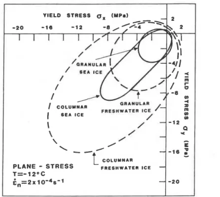
2.1.5.
Failure e m l o p e
The failure envelope is a description of the stress levels at
which a material yields for any combination of compressive and
tensile stress states. For ice, the failure envelope has been
determined by using the combined results of uniaxial compres-
sion tests, confined compression tests and shear strength tests
both for mostly granular sea ice (Timco and Frederking, 1983a,
1984), and columnar sea ice (Nadreau and Michel, 1984; Timco
and Frederking, 1986a) over a range of loading rates and
temperatures. Due to the hexagonal structure of the ice lattice
and the horizontal alignment of the c-axis in the columnar ice,
there is a marked difference in the failure envelope between the
two ice structures (see Fig. 2). This figure compares the failure
envelope for sea ice with that of freshwater ice for both granu-
lar and columnar sea ice for plane stress conditions. It is
evident that the void volume (brine and air) in sea ice signifi-
cantly reduces the size of the failure envelope compared to that
For
freshwater ice
at the
same loading rate
and
temperature. For
columnar
ice, the failurr: envelope extends much further into
compression-compression quadrant than that for granular
ice.
This implies that columnar structured ice in a confined state
(such as
that
in an ice
cover)
will
snstain much higher stresses
before railure than granular structured ice. This
has
clear
catrons when viewed in terms of the forces which
an
ice sheet
can exert on a structure. A mathematical description of the
three-dimensional failure envelope based on a modified n-type
yield function has been given for both granular and columnar
1220
Sinha, Timco, and Frederking: Recent advances in ice mechanics in Canada
Appl Mech Rev vol40, no
9,
Sep 1987
FIG.
2.
Comparison of the failure envelopes for both granular and columnar sea ice and freshwater ice
in
the horizontal plane (after Timco and
Frederking,
1984).
PLANE
-
STRESS
FRESHWATER
I C E-
T=-12OC
6 , = 2 ~ 1 0 ' ~ s ' l
-
structured ice (Timco and Frederking, 1984, 1986a), allowing its
use in analytical models. The importance of using the correct
yield function in these types of analyses has been demonstrated
by McKenna et al(1983).
Using triaxial test results of Jones (1982) and Nadreau and
Michel (1985) on granular freshwater ice, Nadreau and Michel
(1986b) proposed a new formulation for describing the failure
envelope. The proposed yield surface models the pressure melt-
ing, sensitivity of the ice at high confining pressures. It is a
- 2 0
cubic function of the invariants of the stress tensors. The
three-dimensional surface defined bv this criterion is teardr0~-
shaped and symmetrical around the hydrostatic line. The volume
of this teardrop envelope is rate sensitive and increases with the
increase in strain-rate.
2. I. 6. Fracture toughness
The fracture toughness (or critical stress intensity factor
(K,,)) has been measured by a few investigators for both
freshwater ice and sea ice. The understanding of this property
as a material property of ice is, however, still in its infancy.
For freshwater ice, measurements of K,, have been per-
formed by Timco and Frederking (1982) in a test series compar-
ing several mechanical properties measured under comparable
conditions. Hamza and Muggeridge (1983) measured the non-
linear fracture toughness of small ice beams while investigating
the effects of loading rate, temperature, and specimen size.
A
field test series measuring the fracture toughness of large beam
specimens was performed by Parsons and Snellen (1985). They
measured the highest Kl, values reported to date with mean
values of K,, approximately 200-250 kPa m1l2 depending
upon the loading direction. Finally, Timco and Frederking
(1986b) investigated the effects of both anisotropy and micro-
cracks on the fracture toughness of fine-grained columnar ice.
They found that the presence of microcracks causes a decrease
in the apparent fracture toughness of the ice. Based on these
tests, Cormeau et al (1986) performed a finite element (FE)
analysis of this process. They found that depending upon the
position of a microcrack relative to the main crack, there can be
an amplifying or shielding effect on the stress intensity factor.
Overall, the F E analysis showed excellent agreement with the
test results, and provided valuable insight into the mechanics of
fracturing in ice.
The fracture toughness of sea ice has been measured by
Timco and Frederking (1983b) on small beam samples and by
Parsons et al (1986) on large beams. The latter study investi-
gated the effects of anisotropy and temperature and showed
that K,, increases with decreasing temperature with mean
values of the order of 500 kPa m'/2 at -25OC and 150
kPa m1I2 at
-
10°C.
2.2. Rheology: Introduction
Rheology in ice is part of a broad subject that involves the
stress-time-temperature dependent deformation and fracture
of polycrystalline materials at elevated temperatures. Polycrys-
talline ice in nature is generally an anisotropic, nonlinear
viscoelastic solid and its mechanical behavior is described by
the generalized Hooke's Law relating strains
E,to stress
9:
where Sf, are the compliances. Granular snow ice, for all
practical purposes, may be considered as an isotropic material
and its deformation properties may be described by Sll
=S2,
=S,, and S12
=S2,
=S,, (i
+
j). For commonly observed trans-
versely isotropic (or orthotropic) columnar grained lake, river or
sea ice, classified as S-2 ice, we are concerned usually with the
compliances
Sll
=S2,
#S,,, in which the Cartesian axes are
chosen in order to have the 3-axis along the axis of the
columnar grains, ie, the vertical (growth) direction, and the
1-axis and 2-axis in the plane of the ice cover perpendicular to
the growth direction, hence in the horizontal plane. For stresses
applied along 1-direction, which is the case in many engineering
situations, the important lateral compliances are S2, and $1.
A minimum of three macroscopically observed strain com-
ponents describe the deformation of any material irrespective of
operational conditions. Regardless of loading conditions, the
deformation, E,
,
of any polycrystalline material (including ice),
Appl
Mech Rev vol40, no 9,
Sep
1987
Sinha, Timco, and Frederking: Recent advances
in
ice mechanics in Canada
1221
at high homologous temperatures can be described phenomeno-
logically as (Sinha, 1978b)
where
q e
is pure elastic and immediately reversible,
is
delayed elastic and recovers with time, and
el,
is the viscous or
permanent strain. Delayed elasticity is particularly noticeable in
ice because it is always, in nature, at high temperatures.
The simplest method for bringing out the macroscopic be-
havior is the uniaxial tensile or compressive test. Two com-
monly applied experiments to determine material properties for
engineering applications are the uniaxial "constant stress" creep
and the "constant strain rate" deformation tests. Ideally a
certain stress is suddenly imposed and held constant in the
creep tests; in the other tests, a certain strain rate is suddenly
imposed and held constant.
2.2.1. E k t i c i t y
Unless low amplitude and very high frequency loading, in
the order of MHz, is involved, it is almost impossible to have
only elastic deformation with no contributions due to grain-
boundary sliding or delayed elastic and viscous deformation.
This observation is applicable to deformation parallel as well as
normal to the axis of loading. Consequently, the compliances
S,,
given by the observed ratio,
€,/a,
or the corresponding
moduli and the ratio between lateral strain and longitudinal
strain reflects the contribution due to nonpure elastic deforma-
tion. It is preferable, therefore, to use the term "effective
modulus" for the reciprocal of compliance or
o,/~,
except
where Young's modulus and other elastic moduli, in the formal
sense, are intended.
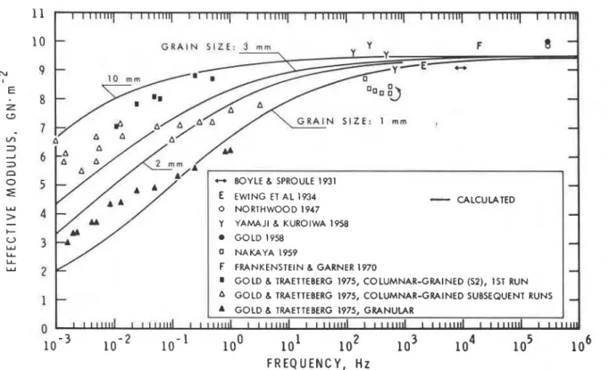
The dependence of the effective moduli, for freshwater ice,
on the rate of loading and temperature and grain sue, for
loads less than 0.5 MN m-2 in uniaxial loading, has been
studied experimentally by Gold and Traetteberg (1975) and
Traettenberg et al (1975). These along with many previous
results, were compiled by Gold (1977). Figure 3, taken from
Sinha (1979a), shows that the effective modulus increases with
increase in rate of loading and grain size. Similar rate sensitivity
was noted in saline water ice by Murat (1980) and Murat and
Lainey (1982). The illustration also shows that the experimental
observations, however complex, are reasonably predicted by a
simple micromechanically based rheological model to be dis-
cussed later. The applicability of this model in the case of saline
ice can be seen in Sinha (1981d), which also explains why sea
ice appears to be more ductile than freshwater ice.
Shear modulus has also received some attention. While ex-
amining the bearing capacity of saline ice covers, Lainey (1982),
and Lainey and Tinawi (1983) realized and emphasized the
importance of shear deformation. Selvadurai (1981) modelled
an ice cover, containing a primary snow ice layer and secondary
columnar zone, as a composite structure assuming the sec-
ondary ice as a Pasternak-Vlazov-type elastic layer which pos-
sesses only shear interaction. Murat and Degrange (1986) ex-
amined the relative influence of shear and flexural deformation
on the deflection of laboratory made transversely isotropic,
saline ice beams. They concluded that the shear deflections
could be 2 to 3 times greater than those expected for an
isotropic material.
2.2.2.
Creep
The term "creep" is defined as "the slow deformation of a
material" according to BS 5168 or British Standard Glossary of
Rheological terms (1975). This definition is broad enough to be
universally acceptable. One might object to the term
"slow"-however,
slow or fast are only relative terms. It has
been pointed out by Sinha (1979b) that a very short creep time
of 10 s at a homologous temperature of 0.96 T, is equivalent to
a creep time of 12 days at 0.7 T,, 36 years at 0.6 T, and about
half a million years at 0.5 T,. It should be pointed out here, to
give a feeling of the actual thermal state, a homologous temper-
ature of 0.96 Tm in ice is a temperature of -10°C and a
temperature of 0.5 Tm in austenitic stainless steel could be as
high as 700°C.
G R A I NS I Z E :
3 m m-
-
-
BOYLE 6 SPROULE 1931-
E
EWlNG ET AL 15'34-
CALCULATED 0 NORTHWOOD 1947-
Y YAMAJl 6 KUROIWA 1958 GOLD 1958-
NAKAYA 1959 F FRANKENSTEIN 6 GARNER 1970-
8 GOLD 6 TRAETTEBERG 1975, COLUMNAR-GRAINED (S2), 1ST RUN
1
-
A GOLD 6 TRAETTEBERG 1975, COLUMNAR-GRAINED SUBSEQUENT RUNS-
GOLD 6 TRAETTEBERG 1975, GRANULAR