Characterizing Reaction Bandwidths in a Position-Controlled Robotic Arm
by Selam Gano Submitted to the
Department of Mechanical Engineering in Partial Fulfillment of the Requirements for the Degree of
Bachelor of Science in Mechanical Engineering at the
Massachusetts Institute of Technology June 2018
0 2018 Selam Gano. All rights reserved.
r-The author hereby grants to MIT permission to reproduce and to distribute publicly paper
and electronic copies of this thesis document in whole or in part.
Signature redacted
Signature of Author:
r
cDepartment of Mechanical Engineering ;6
, / May 11, 2018-C
Signature redacted
8
Certified by: 0.-2
Alberto Rodriguezj7 $
Professor of Mechanical Engineering
~ W L~i Thi ~i S~ i yv
zignaiure
redacied
Accepted by:
MASSACHUS S TITUTE OF TECHNOLOGYSEP 13Z018
LIBRARIES
ARCHIVES
Rohit Karnik Professor of Mechanical Engineering Undergraduate OfficerZ1) IQ)
C3
Characterizing Reaction Bandwidths in a Position-Controlled Robotic Arm
by Selam Gano
Submitted to the Department of Mechanical Engineering on May 11, 2018 In partial Fulfillment of the Requirements for the Degree of
Bachelor of Science in Mechanical Engineering
ABSTRACT
Position-controlled robotic manipulators remain an industry standard but are ill-suited for guarded move approaches to advanced manipulation. Adding additional feedback with the expectation that a position-controlled system can account for it cannot guarantee successful implementation. To explore and define the limitations of position-controlled arms, I attempt to characterize different motion and force bandwidths of a large, 6-DOF robotic arm. Peak force and motion overshoot measurements were taken at varying speeds of the robot. These experiments showed that at speeds as low as 10 mm/s, the robot still exerted over 40 Newtons of force, enough to crush objects typically used for manipulation tasks. Overcoming these issues in using position-controlled arms are difficult to account for with software approaches, but different mechanical solutions can be envisioned to combat this problem in robotic manipulation.
Thesis Supervisor: Alberto Rodriguez Title: Professor of Mechanical Engineering
Contents
1 Introduction ... 3
2 Background... 3
2.1 Traditional Robotic Environm ents... 3
2.2 A dvanced Robotic Environm ents ... 3
3 D esign and Experim ents ... 4
3.1 The Open-Loop M otion Bandwidth... 5
3.2 The Closed-Loop Force Bandwidth... 6
4 R esults and D iscussion... 6
4.1 M otion Overshoot M easurem ents... 7
4.2 Peak Force M easurem ents ... 8
5 C onclusions ... 9
6 A cknow ledgem ents... 10
1
Introduction
Though impedance and force-controlled approaches are gaining popularity [5], position-controlled robotic manipulators remain an industry standard. The comparative costs, availability, and other factors can thus force the attempted implementation of guarded-move approaches on systems that are ill-suited for such pathways. This is primarily due to delays in the system and a lack of compliance, which make such high-inertia, position-oriented systems unable to respond to feedback effectively.
Delays in a robotic system can come from electrical or software processes (sensor
feedback delay, computation processing time, etc.) or from physical limitations due to the system's inertias (physical dead-bands and unstable conditions). Many approaches to circumventing this problem in endpoint control have been envisioned, however it must first be established exactly how and where standard industrial position-controlled robotic arms may fail. To explore and define the limitations of position-controlled arms, I attempt to characterize different motion and force bandwidths of a large, 6-DOF robotic arm.
2
Background
2.1 Traditional Robotic Environments
The initial work environments which heavily featured the first industrial robots tended toward welding and car manufacturing [4]. Because the advent of the industrial robot focused on moving objects to exact and precise positions in a given workspace [2],
position control was emphasized to improve accuracy of a robot, rather than robustness to uncertainty. Still today in these applications, position control dominates, and the position paradigm was not majorly deviated from until the 1980s when impedance control and other types of feedback for manipulation were explored [4]. These later frameworks have yet to displace much of the hardware offered in the industrial robotics market, often due to cost and the simple fact that position-controlled manipulators are still effective in those industrial areas where robots were first commercialized [7]. As manipulation robotics moves to other, more stochastic tasks such as picking, placing, sorting, or packaging everyday items, the position control framework can become much less effective.
2.2
Advanced Robotic Environments
In many manipulation and especially "picking" tasks, position feedback becomes a poor choice for closing a control loop, as the true position of an object relative to a
manipulator can be difficult to ascertain. Unlike automotive or welding environments for which industrial robots were first initially popularized, more advanced robotic
environments for picking, sorting, and placing household items are more stochastic and involve higher uncertainty. Different methods have been devised to correct for this, across several disciplines, including perception-based software approaches, which focus
on determining an object's position so that a position-controlled arm can still be effective. Impedance control methods and position-impedance hybrids thereof have also been proposed (such as the work in [3] and [5]) to tackle the problem at a more fundamental level.
Some of these novel manipulation approaches can and have been implemented, at least within a software framework, on position-controlled industrial robots, including one used in this work. However, using these impedance-controlled or guarded move approaches on machines mechanically designed for quite different environments can prove unwieldy at best and destroy objects or manipulators themselves at worst. This work seeks to quantify and clearly define just how ill-suited position-controlled arms may be for advanced manipulation tasks by characterizing an example 6-DOF robotic system that tries to execute a guarded move.
3
Design and Experiments
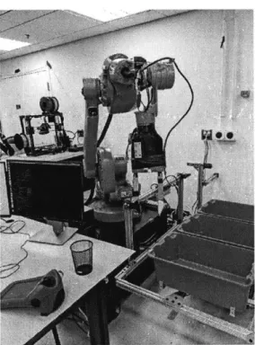
Figure 1: The 6-DOF arm used in these experiments, an ABB 1600. A parallel jaw gripper is
attached to the end.
The 6-DOF arm used in these experiments was an ABB 1600 arm, capable of speeds up to 7 meters per second. When using the position-oriented control modes of this arm, which is designed for welding applications, the 6-DOF arm can be very precise, and decelerates accordingly to reach its position safely and accurately. However, in advanced manipulation tasks, it became desirable to execute "guarded" moves--motions where the robot moved at a speed without knowing when it should decelerate, and executing commands based on contact or feedback with an object. These guarded, feedback-based
approaches require more information than only position, and proper manipulation would require fast responses to feedback, inherently limited in this case by the aforementioned delays and lack of compliance in the system. Some amount of overshoot in the guarded-move modes of this particular 6-DOF arm have been observed, and until now, never quantified in the context of the full manipulation system.
A variety of metrics could be used to characterize the overshoot of the 6-DOF arm, but those most feasible and relevant in the context of this system were determined to be motion overshoot and peak force. Peak force measurements characterized the closed-loop force bandwidth of the system, wherein peak force measurement of the robot after a commanded stop is measured. The speeds at which peak force was measured were
limited by the maximum capacity of available weight sensors, which could not handle the full range of high-impact forces that can be produced by this 6-DOF arm.
3.1 The Open-Loop Motion Bandwidth
An experiment was designed to capture the motion overshoot of the 6-DOF arm at varying speeds. The ABB 1600 was put into a guarded move mode, which did not command any deceleration before impact. Thus, the true overshoot of the system could be measured this way. Contact was detected by weight sensors on the underside of totes, which are typically used for manipulation tasks such as picking and sorting objects. Once an item in the bin is disturbed and force transfers to weight sensors, the weight sensors register the impact and report it to the central computer. The 6-DOF arm then issues a stop command. Each of these reporting steps leaves an opportunity for software and firmware delays, so the total overshoot is a function of both physical inertia and delays in the control loop. It is more difficult to fully separate these elements' contributions to overshoot, so overshoot was assessed across all of these parameters.
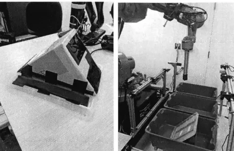
In order to protect the weight-sensing load cells from damage due to impacts, and because for the motion overshoot the system only needed to measure the instance of impact (rather than quantify its magnitude) a simple wedge was constructed, which displaced laterally when contacted by the endpoint of the 6-DOF arm. While the arm overshot past its desired position, the wedge moved laterally, and avoided high forces on the weight sensors.
Involving the wedge also had the benefit of closely simulating real manipulation scenarios, and the scenario in which this type of guarded move motion is used, where force-guarded moves can be used to detect contact with objects. Evaluating the system based on its contact with the wedge was similar to real situations in which overshoot was a significant barrier to achieving manipulation tasks with this robot.
Figure 2: The lightweight wedge, constructed out of simple cardboard and plastic, placed in totes used for manipulation tasks. Teflon was adhered to the bottom face to reduce sliding friction, so
that contact with the wedge would have minimal influence on the downward speed of the robot endpoint.
The test itself involved vertical downward motion of the robot's endpoint at varying speeds. The magnitude of overshoot was quantified using the robots own position sensing feature, whiqh reported both the position where contact was detected and the final,
overshoot position of the endpoint. The overshoot was calculated from simply the difference between these two reported values.
3.2 The Closed-Loop Force Bandwidth
The second test used to characterize the system aimed to evaluate the closed-loop force bandwidth. In this experiment, the moving wedge was replaced with a piece of dense foam to add very minimal additional compliance to the system (again for the safety of the weight sensors used). The endpoint of the robot arm was commanded to again move vertically, this time pressing directly on the bottom of the tote (via the flat layer of foam). The system was again commanded to report the position when impact was detected and the actual final position, but also reported the magnitude of the impact in kilograms. The expectation of a system with good response bandwidth is that both the amount of overshoot distance and the the magnitude of peak forces would be relatively low. Objects used in manipulation tasks for this particular 6-DOF arm range from 0.1 to 2 Kg in weight and 5 to 40cm in size, so the results of these experiments were evaluated in this context.
uJ
4.1 Motion Overshoot Measurements
Table 1: Overshoot distances at different commanded speeds of the 6-DOF arm
Robot Speed (mm/s) Average Overshoot (mm) Standard Deviation (mm)
50 22.80 0.287 100 43.03 2.478 150 58.22 0.877 200 70.57 0.628 250 79.19 0.751 300 87.99 1.090
To characterize the overshoot in motion, 5 trials were conducted at each speed. In each trial, the robot was commanded to move to a position, record the position of impact registered by weight sensors, and report the actual, final position of the endpoint. The overshoot is therefore the difference between the final physical position and position at which the system registered a contact. Between each trial at a particular speed, standard deviations remained relatively low and generally increased with robot speed.
The average overshoot for a velocity as low as 50 mm per second of motion was 22.8 mm, a surprisingly high result. When manipulating household objects of the
aforementioned 10-40cm range, this amount of overshoot could displace an object as much as 5-25% on a particular axis of orientation and gets progressively worse at higher and higher speeds.
Motion Overshoot
100 90 E80 70 0 o60 50 40 30 < 20 . 10 0 50 100 150 200 250 300 Robot Speed (mm/s)Figure 3: A graph of the motion overshoot values. The relationship between overshoot and speed
was not quite linear, which may indicate that increases in force are also not linearly correlated with speed in this system.
It should be noted that in motion overshoot tests (which could handle higher speeds than peak force overshoot tests) some inconsistencies may have been in place due to conflict with the system control loop. The relationship between control loop step size and physical speed was such that vibrations occurred and interfered progressively more as
speed was ramped up. At 200 mm/s the robot endpoint was visibly shaking as it descended to the point of contact, and this may have still occurred at less noticeable magnitudes at velocities prior to 200 mm/s. This vibration may have had an impact on the absolute recorded values of overshoot but was consistent across all measurements taken. 4.2 Peak Force Measurements
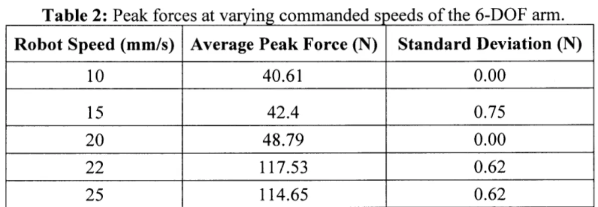
Table 2: Peak forces at varying commanded speeds of the 6-DOF arm. Robot Speed (mm/s) Average Peak Force (N) Standard Deviation (N)
10 40.61 0.00
15 42.4 0.75
20 48.79 0.00
22 117.53 0.62
25 114.65 0.62
To characterize the peak forces of the robot in overshoot after contact was registered, 3 trials were conducted at each speed. The speed values for peak force tests were
necessarily lower than speeds in overshoot measurements, due to the capacity of weight sensors in the system-the weight sensor array had a capacity of up to 20 kg, but this included the 3.5kg weight of the totes. At 25 mm/s the total forces on the system were already as much as 17kg, so testing was halted at this value. The slow speeds did enable consistent measurements, as standard deviation between trials remained low, with some tests reporting identical peak force results for all three trials.
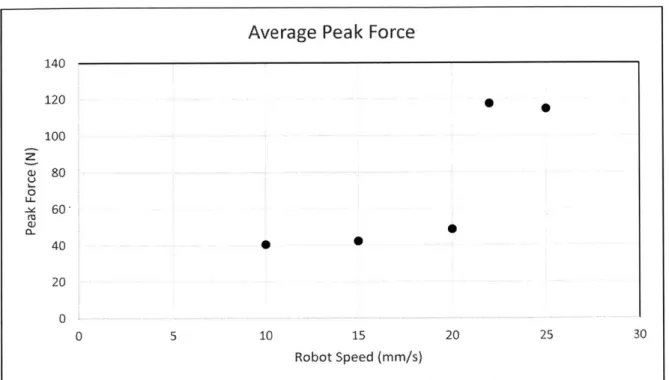
Average Peak Force 140 120 100 80 0 ~e60' 01. 40 00 20 0 5 10 15 20 25 30 Robot Speed (mm/s)
Figure 4: Average peak force measurements shown in a scatter plot. The results were still
consistent within trials, but sporadic and showed little evidence of a clear relationship across the values measured.
The average peak force for these very low speeds was, again, surprisingly high. At only 10 mins, a very slow speed for this 6-DOF arm, a peak force of 40.61 N or over 4 kg was reported. This is not only a large value compared to the weights of typically manipulated objects (0.1-2.0kg), but can also outright destroy the typical objects that manipulators seek to handle, such as tissue boxes and packages of light bulbs, which buckle or break under loads as small as 1 to 1.5kg.
Though peak force was measured at very low speeds, where the relationship between velocity and force may not be as linear, measurements had a much more sporadic distribution than in motion overshoot tests. It is difficult to draw conclusions about the overall relationship between force and velocity, therefore, from the peak force
measurement. However, it is still clear that the peak forces of the robot endpoint in its overshoot condition, even at very low speeds, are enough to crush typical objects and therefore not ideal for advanced manipulation tasks.
5
Conclusions
The maximum speed of this position-controlled arm is 7 meters per second, or in terms of these experiments, 7000 mm/s. Comparing that speed to overshoots at 10-300 mmn/s, and peak forces at a mere 10-25 mmn/s, shows how lacking position-controlled arms can be in their ability to perform guarded moves. Operating within the framework of these
position-controlled arms truly requires position-controlled approaches, and attempting to
implement guarded moves by only changing a software framework is fraught with complications.
This example characterization of an ABB 1600 arm, which has a common topology and control scheme for industrial robots, may point to mechanical adjustments to make more impedance-control and guarded-move friendly machines, as it does not appear these can be achieved effectively with a software-only approach. A variety of solutions can be
imagined and have been implemented in other work. Changing the structure of the arm altogether, such as the Kuka Lightweight Arm [1] is one approach, but would be difficult to implement on an existing robot. An alternative approach may be mechanically
modifying a position-controlled arm by simply attaching an additional device, a gripper or wrist-like mid-layer, where separately controlled hardware could handle the more
stochastic movements necessary to achieve advanced manipulation. This could still leverage the positive attributes of position-controlled arms by moving to precise points at high speed, and still execute guarded moves at high speeds using impedance-based methods at the "wrist" or gripper level. This characterization of peak forces and motion
overshoots may inform further exploration into mechanical solutions to this problem for future work.
6
Acknowledgements
Special thanks to Elliott Donlon, who directly supervised this project and provided regular advice and guidance. I would like to thank Maria Bauza, who provided some key guidance and the software framework for our experimental setup. Peter Yu aided
tremendously in troubleshooting any software issues that arose while testing. Thanks also to Michael Chuah and Juan Romero, who kindly lent me materials on short notice, and
References
[1] R. BISCHOFF et al. "The KUKA-DLR Lightweight Robot Arm - a New
Reference Platform for Robotics Research and Manufacturing ." Robotics (ISR), 2Robotics (ISR), 2010 41st International Symposium on and 2010 6th German Conference on Robotics (ROBOTIK), 9 June 2010.
[2] S. HAYATI and M. MIRMIRANI. "Improving the Absolute Positioning Accuracy of Robot Manipulators." Journal ofRobotic Systems, vol. 2, no. 4, 1985, pp. 397-413., doi:10.1002/rob.4620020406.
[3] N. HOGAN. "Impedance Control: An Approach to Manipulation: Part II-Implementation." Journal of Dynamic Systems, Measurement, and Control, vol. 107, no. 1, 1985, p. 8., doi:10.1115/1.3140713.
[4] R. MURRAY et al. A Mathematical Introduction to Robotic Manipulation. CRC Press, 1994.
[5] M. H. RAIBERT and J. J. CRAIG. "Hybrid Position/Force Control of
Manipulators." Journal of Dynamic Systems, Measurement, and Control, vol. 103, no. 2, June 1981, p. 126.
[6] P. RANKY "Automotive Robotics." Industrial Robot: An International Journal, vol. 31, no. 3, 2004, pp. 252-257., doi:10. 1108/01439910410532314.
[7] G. ROSENBERG et al. "Robotic Industries Association." Robotics Online, 25 Apr. 2017, www.robotics.org/content-detail.cfm/Industrial-Robotics-Tech- Papers/Servo-Spot-Welding-Offers-Superior-Performance-and-Lower-Lifetime-Costs-for-Auto-Manufacturing/contentid/6509.