A
A
C
C
A
A
R
R
B
B
O
O
N
N
N
N
A
A
N
N
O
O
T
T
U
U
B
B
E
E
B
B
E
E
A
A
R
R
I
I
N
N
G
G
A
A
N
N
D
D
S
S
T
T
O
O
D
D
O
O
L
L
A
A
R
R
O
O
T
T
O
O
R
R
byEugene Hightower Cook
B.S. Aerospace Engineering, 2006 University of Maryland, College Park, MarylandSubmitted to the Department of Aeronautics and Astronautics in partial fulfillment of the requirements for the degree of
Master of Science in Aeronautics and Astronautics
at the
MASSACHVSETTS INSTITVTE OF TECHNOLOGY September 2008
Copyright ©2008 Eugene H. Cook. All rights reserved.
The author herby grants to MIT permission to reproduce and to distribute publicly paper and electronic copies of this thesis document in whole or in part.
Author
Department of Aeronautics and Astronautics 20 August 2008
Certified by
Dr. David J. Carter Principal Member of the Technical Staff The Charles Stark Draper Laboratory, Inc. Thesis Supervisor Certified by
Prof. Zoltán S. Spakovszky H.N. Slater Associate Professor of Aeronautics and Astronautics Thesis Advisor
Accepted by
Prof. David L. Darmofal Associate Department Head Chairman, Committee on Graduate Students
2
3
A
A
C
C
A
A
R
R
B
B
O
O
N
N
N
N
A
A
N
N
O
O
T
T
U
U
B
B
E
E
B
B
E
E
A
A
R
R
I
I
N
N
G
G
A
A
N
N
D
D
S
S
T
T
O
O
D
D
O
O
L
L
A
A
R
R
O
O
T
T
O
O
R
R
byEugene H. Cook
Submitted to the Department of Aeronautics and Astronautics on 20 August 2008 in partial fulfillment of the requirements for the degree of Master of Science in Aeronautics and Astronautics
ABSTRACT
A nano-scale rotor supported on a cantilevered multi-wall carbon nanotube (MWNT) shaft (Stodola configuration) is proposed. The nanotube is also expected to function as the bearing, since individual walls of a MWNT are not strongly bonded and can slide on each other with low friction. While MWNT based rotors have been previously constructed, they have so far been limited to horizontally oriented nanotubes. The rotor uses a vertically aligned tube, which allows superior control of the rotor geometry, enabling improved rotor balancing and axisymmetric features such as electrodes or blades.
The rotor is proposed as a test stand for measuring inter-wall friction in MWNTs. The low friction in nanotubes has been studied with simulations and experiments, and while it is agreed that relative motion between walls is possible, there is much debate about the qualitative nature of the friction force between walls. Furthermore the reported quantitative values of friction vary by as much as ten orders of magnitude. The proposed rotor might be used to gather new friction data on rotating MWNT bearings at higher speeds that previously attempted. In addition, identical rotors fabricated on nanotubes of varying size, type, and crystalline quality might provide a large dataset that could be used to find correlations between friction behavior and these factors. Applications for the rotor beyond a friction testing apparatus could include pumps to work with existing micro-chemical sensors, gyroscopes, energy storage flywheels, and turbomachinery for power generation.
A fabrication process for the proposed rotor was developed, and is being refined. An isolated vertically aligned MWNT is grown by chemical vapor deposition (CVD), from a nickel catalyst dot defined with electron-beam lithography. A silicon dioxide sacrificial layer is applied, followed by a polysilicon layer from which to cut out the rotor. The rotor etch is performed by cryogenic reactive ion etching (RIE), patterned with electron-beam lithography. The rotor is released from the substrate by
hydrofluoric acid vapor. One iteration of the fabrication process was completed, and further iterations are planned to complete a functional device. Actuation of the rotor would be achieved by directing jets of air at blades on the rotor, and an alternative electrostatic actuation concept is also proposed. A dynamic model of the rotor performance based on classical simple beam theory and rigid body dynamics indicates that speeds on the order of thousands to millions of revolutions per minute should be achievable, while avoiding the thirteen potential failure mechanisms analyzed.
Technical Supervisor: Dr. David J. Carter Principal Member of the Technical Staff The Charles Stark Draper Laboratory, Inc.
Thesis Advisor: Prof. Zoltán S. Spakovszky
H.N. Slater Associate Professor of Aeronautics and Astronautics Massachusetts Institute of Technology
4
5
A
CKNOWLEDGMENTS
First I am greatly indebted to Dr. David J. Carter, my mentor at Draper Laboratory. This project was Dave’s original brainchild, and his enthusiasm, knowledge, and dedication are the prime movers that continue to drive this research. Many thanks also go to Prof. Zoltán Spakovszky, whose contagious excitement and extremely valuable perspective have contributed immensely to this work and to my journey through MIT. I am also very thankful to Dr. Marc Weinberg, of Draper Laboratory, who provided so much wisdom and counsel on both things technical and the Ways of the Lab.
I would like to especially thank those people at Draper who contributed to this project with their own efforts, and without whom I could not have accomplished much. Parshant Kumar, Pete Miraglia, and Bill Teynor have my gratitude for taking their own time to contribute directly to the project. I am also indebted to everyone in the fab who has given me invaluable advice, including Mark April, Janis Aten, Jon Bernstein, Connie Cardoso, Dick Caruso, Amy Duwel, Biga Ganesh, Manuela Healey, Maria Holmboe, James Hsiao, Tom Langdo, John Le Blanc, Mark Mescher, Tony Monteiro, Tenzin Nyinjee, Mert Prince, Dan Pulver, Livia Racz, Henry Raczkowski, and Ricky Soong.
From the education office at Draper, I am very grateful to Linda Fuhrman and Gail DiDonato, as well as George Schmidt. These folks have been so very helpful to me in finding my footing and making sure I am taken care of. Thanks also to Mitch Hansberry, Ralph Pupa, and John Mahoney who helped with designing, machining, and rapid prototyping of various parts.
I would like to thank Dr. Yong Zhang and Dr. Anthony Garratt-Reed for much assistance with the microscopes at the MIT Electron Microscopy Shared Experimental Facility. I would also like to thank the people at Boston College who provided all the nanotube growth for this work. Thanks to Prof. Zhifeng Ren for bringing his nanotube growth expertise to bear, and thanks to Trilochan Paudel for doing so much nanotube growth. Thanks also to Dr. Dezhi Wang and Dr. Yucheng Lan for training and assistance with the Boston College TEM facility.
At the gas turbine laboratory at MIT, I am thankful to have met several delightful people. Thanks to Bernard Yen for graciously allowing the use of pictures of his permanent magnet turbine generator in this thesis. Thanks to Prof. Ed Greitzer, Dr. Choon Tan, and Holly Anderson for welcoming a Draper Fellow to the fold.
Personally I want to thank my good friends in the area. Thanks to my fellow Fellow Ryan Odegard for his outstanding ability to find interesting things to do, and for his “well aligned” sense of humor. I also want to thank Yong-yi Zhu. I have known him for a long time, and I consider any time with him well spent. Thanks as well to my officemates here at Draper: Jon Varsanik, Eli Weinberg, and Jonathon Cox, cool guys all.
I owe my parents more than I can measure, as it is their hard work that has brought me to the position where I can achieve this dream. Thank you for carrying me here. I want to thank my brother Gordon, whom I am very proud to count among my kin, and who is so much fun to be around. Finally I want to thank my incredible fiancée, Kyra. It is her love and support that I would turn to when my own steam seemed to be running low, and I believe there is as much of her sweat in here as my own. She is the best companion I could have asked for.
6
This thesis was prepared at The Charles Stark Draper Laboratory, Inc., under Internal Research and Development projects 21160-001: Carbon Nanotube Device Development, 21812-001: Carbon Nanotube Applications, and 23027-001: Carbon Nanotubes.
Publication of this thesis does not constitute approval by Draper or the sponsoring agency of the findings or conclusions contained herein. It is published for the exchange and stimulation of ideas.
Eugene H. Cook 20 August 2008
7
C
ONTENTS
Abstract ... 3
Acknowledgments ... 5
List of Figures ... 9
List of Tables ... 12
Nomenclature ... 13
Acronyms ... 17
1
Overview ... 19
1.1 Goals of the Project ... 20
1.2 New Accomplishments... 21
1.3 Challenges ... 24
1.4 Impact of the Project ... 25
1.4.1 A Nanoscale Carbon Nanotube Friction Test Stand ... 25
1.4.2 Applications ... 26
2
Background – Nanotube Properties and Prior Work ... 28
2.1 Atomic Structure of Carbon Nanotubes ... 28
2.1.1 The Ideal Carbon Nanotube Molecule... 28
2.1.2 Defects in Carbon Nanotubes ... 31
2.1.2.1 Types of Defects ... 31
2.1.2.2 Identifying Defects ... 35
2.1.2.3 Effects of Defects ... 39
2.1.2.4 Mitigating Defects ... 40
2.1.2.5 Self-Repair ... 41
2.2 Friction in Carbon Nanotube Bearings ... 41
2.2.1.1 Linear Sliding Friction Experiments ... 43
2.2.1.2 Rotating Friction Experiments ... 46
2.2.2 Theoretical Studies of Friction in Carbon Nanotubes ... 47
2.2.2.1 Linear Friction Simulations ... 48
2.2.2.2 Rotational Friction Simulations ... 50
2.2.2.3 Simulations of Combined Rotation and Linear Sliding ... 51
2.2.3 Remaining Work on Carbon Nanotube Friction ... 52
3
Device Model ... 54
3.1 Summary of Constraints on Device ... 55
3.2 Statics ... 55
3.2.1 Euler Beam Bending Theory ... 56
3.2.2 Carbon Nanotube Buckling ... 58
3.2.2.1 Euler Buckling ... 58
3.2.2.2 Shell Buckling ... 58
3.2.3 Eccentric Column Loading ... 59
3.3 Dynamics – The Stodola Rotor Model ... 60
3.3.1 Equations of Motion ... 62
3.3.2 Eigensolution – Free Response ... 63
3.3.3 Forced Response ... 67
8
3.3.3.2 Dynamic Lateral Deflection Constraint ... 70
3.3.3.3 Dynamic Angular Deflection Constraint ... 71
3.3.3.4 Dynamic Beam Stress Constraint ... 73
3.3.3.5 Substrate Clearance Constraint... 74
3.3.3.6 Beam Telescoping Constraint ... 74
3.3.4 Rotor Material Fracture Constraint ... 76
3.4 Optimal Device Design ... 76
4
Experimental Approach ... 79
4.1 A Fundamental Orientation Change ... 79
4.1.1 Advantages of the Orientation Change ... 79
4.1.2 Consequences of the Orientation Change ... 80
4.2 Fabrication ... 81
4.2.1 Carbon Nanotube Process Compatibility ... 81
4.2.2 Device Fabrication Process ... 89
4.2.2.1 Catalyst Patterning ... 90
4.2.2.2 Carbon Nanotube Growth ... 93
4.2.2.3 Silicon Dioxide Sacrificial Layer ... 94
4.2.2.4 Poly-Silicon Rotor Layer ... 94
4.2.2.5 Rotor Lithography ... 95
4.2.2.6 Silicon Rotor Etch ... 96
4.2.2.7 Silicon Dioxide Release ... 98
4.3 Actuation Mechanisms ... 99
4.3.1 Air Jet Drive ... 100
4.3.2 Capacitive Electrostatic Motor ... 102
4.3.3 Laser Radiation Pressure Drive ... 105
4.3.4 Manual Manipulation ... 107
4.4 Testing and Data Collection ... 107
5
Conclusions ... 109
5.1 Contributions of the Project ... 109
5.2 Follow On Work ... 109
5.2.1 Development and Improvement of the Fabrication Process ... 109
5.2.2 Science ... 111
5.2.3 Applications ... 111
6
Appendix –Derivation of Static Constraints ... 114
6.1 Euler Beam Deflections ... 114
6.2 Euler Column Deflections ... 117
6.3 Euler Buckling ... 120
7
Appendix - Derivation of the Equations of Motion ... 125
7.1 Degrees of Freedom ... 125
7.2 Lagrangian of the System ... 127
7.3 Equations of Motion ... 139 7.3.1 Linear X Motion ... 140 7.3.2 Linear Y Motion ... 142 7.3.3 Angular X Motion ... 144 7.3.4 Angular Y Motion ... 152 7.3.5 Angular Z Motion ... 161
References ... 171
9
L
IST OF
F
IGURES
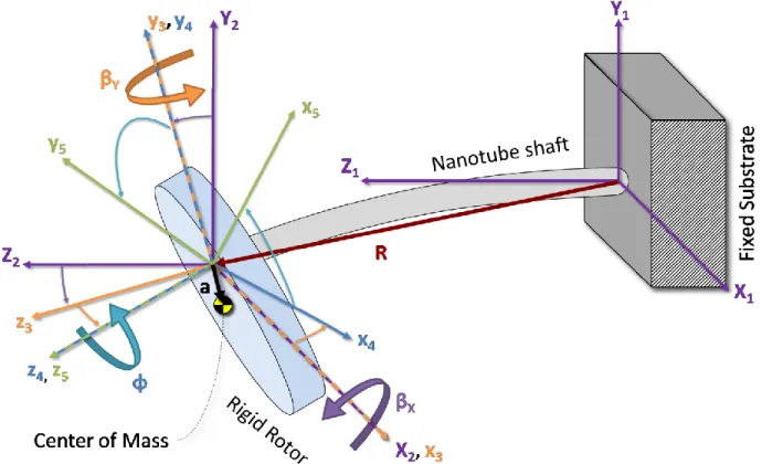
Figure 1-1: A schematic Illustration (not to scale) of the carbon nanotube rotor described here, with wedge-shaped cutaway to show the nanotube structure. A single cantilevered multi-wall carbon nanotube supports the rotor, acting as both the axle and bearing. This configuration is known as
the Stodola Rotor [1]. ... 19
Figure 1-2: A vertically aligned tube allows axisymmetric geometry to be constructed. The grey material represents silicon, or whatever material is used for the device, while the blue material is a sacrificial support material, such as silicon dioxide. ... 22
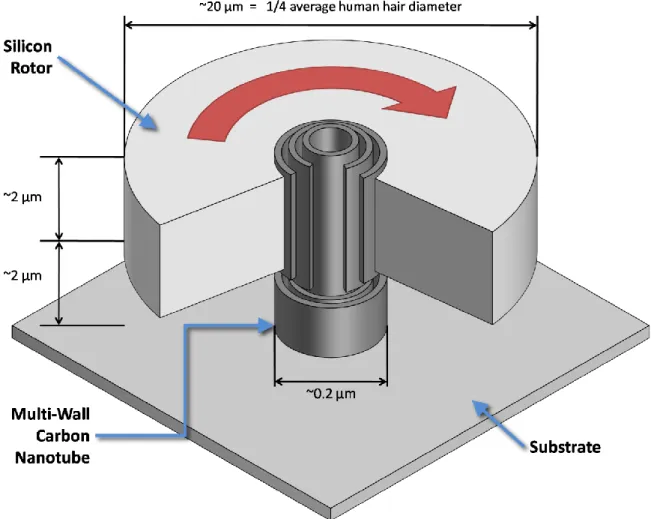
Figure 1-3: Size comparison of the present nano-turbine with a previous micro-turbine generator fabricated by Yen [34]. One layer of the die for that turbine generator is depicted in (a). The micro-turbine rotor (b) has a diameter of 12 mm, compared with the 20 μm diameter of the nano-Stodola rotor (e). The nano-Stodola rotor is closer to the size of the thrust bearing orifices in the micro-turbine (c,d) which are approximately 10 μm in diameter. Images of the micro-micro-turbine in (a,b,c, and d) are provided courtesy of Bernard Yen [34]. ... 23
Figure 2-1: Terminology for carbon nanotubes and related structures. Note that nanotubes are not actually formed by rolling up graphene; this is only a helpful visualization tool. ... 28
Figure 2-2: Carbon nanotube chirality. A graphene sheet can be rolled up around many different angles (a), by joining points A to A’ and points B to B’. The angle is expressed as a vector, based on the two unit vectors in (b). Rolling around different axes produces (c) an “armchair” nanotube, (d) a “zigzag” nanotube, or (e) one possible example of a “chiral” nanotube, which is neither armchair nor zigzag. ... 30
Figure 2-3: A single pentagon or heptagon causes a disclination, introducing curvature into the flat sheet. (a) The effect can be visualized by imagining the original flat sheet. (b) To turn the central purple hexagon into a pentagon, the shaded wedge is removed, and joining the two sides results in a dome-like surface. (c) To form a heptagon, an additional shaded wedge is added, creating a saddle-like surface. ... 32
Figure 2-4: Pentagon-heptagon defects. Wrapping up these graphene sheets, and joining the top and bottom edges would illustrate how (a) a single pentagon-heptagon pair causes a chirality change, while (b) two opposing pairs (making one Stone-Wales defect) cause only local changes. ... 33
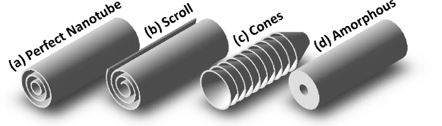
Figure 2-5: Large-scale defects in carbon nanotubes, with an ideal tube for comparison. ... 34
Figure 2-6: Graphene sheets can be wrapped conically, instead of parallel to the tube axis. ... 35
Figure 2-7: Bamboo defects in a carbon nanotube. ... 36
Figure 2-8: TEM can be used to identify (a) edge-terminated sheets, (b) crossed sheets at different depths, (c) curved sheets, and (d) split sheets. ... 37
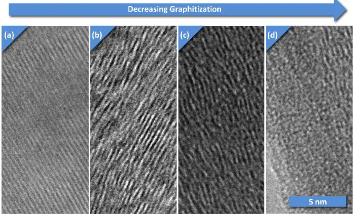
Figure 2-9: Varying degrees of graphitization in carbon nanotubes: (a) defect free, crystalline (b) crystal structure visible, with defects (c) difficult to identify crystal structure (d) completely amorphous. ... 38
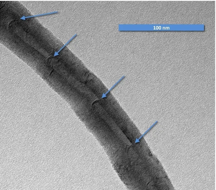
Figure 2-10: We have developed techniques to observe the entirety of tubes up to 20 micrometers in length, and compare structure and defects between regions. ... 38
10
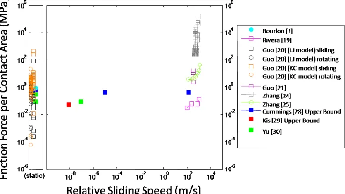
Figure 2-11: Simulated (open markers) and Experimental (closed makers) values from the literature on linear sliding (squares) and rotating (circles) friction in MWNTs. Wide disagreement remains, spanning almost ten orders of magnitude. These data wer converted from the references, and speed computed from various available data, including times, frequencies, and distances given in the references. ... 42 Figure 3-1: The Stodola rotordynamic model consists of a thin rigid disk on a cantilevered shaft. It
includes two translational degrees of freedom (𝑹𝑿, 𝑹𝒀) and three translational degrees of
freedom (𝜷𝑿, 𝜷𝒀, and 𝝓). ... 61 Figure 3-2: Natural frequencies of the Stodola rotor vs. operating speed. The operating speed 𝛀 and
natural frequencies 𝝀 are normalized by 𝟑𝑬𝑰𝒎𝑳𝟑 . This particular plot is for a rotor whose non-dimensional “disk parameter” 𝒅 = 𝟑𝑱𝒎𝑳𝟐 is 18.75, the value for the final design of the device in this research. ... 66 Figure 3-3: The device design space. The color codes indicate which constraint is the limit at each point.
The thick grey bars indicate regions that fail to meet the constraints even at zero speed. (a) A large design space showing where the static constraints come into play. In practice, it would be difficult to construct devices at the larger edges of the space. Furthermore, the optimally performing devices are located towards the bottom left. (b) A close up of the region of interest, where
fabrication is more realistic. The blue contours show the maximum acceptable rotational speed (in millions of revolutions per minute) at each location. (c) The same region, with black contours indicating coast down time (in milliseconds). ... 77 Figure 4-1: Types of nanotubes used for MEMS processing compatibility experiments. (a): Cheap Tubes,
Inc. (b) NanoLab Loose tubes. (c) NanoLab vertically aligned carbon nanotube forcest. ... 82 Figure 4-2: Silicon dioxide coatings on carbon nanotubes. (a) A 300 nm coating applied to a VACNF. (b) A
5 nm coating applied to a loose nanotube. Bottom: loose tubes before (c) and after (d) a 20 nm layer was deposited. ... 83 Figure 4-3: Silicon nitride coatings on CNTs. (a) A 300 nm coating applied to a VACNF. (b) The fact that
the coating and inner nanotube consistently fail at the distance from the substrate on a particular tube indicates that the adhesion is likely strong. (c) A 20 nm coating applied to a loose tube. (d) High resolution TEM imagery shows how the crystalline nanotube structure differs from the
amorphous silicon nitride coating. ... 84 Figure 4-4: Polysilicon and silicon dioxide coatings on a VACNF. The polysilicon shows similar uniformity
and adhesion to as the oxide and nitride layers. The two layers can be seen clearly in the inset (b). ... 85 Figure 4-5: The critical point dryer is effective at preventing stiction. Two samples are shown before (a,b)
and after(c,d) submersion in isopropyl alcohol. On the right, the critical point dryer removed isopropyl alcohol from the sample with out the adverse effects of surface tension, such as the stiction at left, where no critical point dryer was used. ... 86 Figure 4-6: A tube was subjected to HF vapor before oxide (a), and after an oxide coating (b) was
applied, for 20 minutes (c) and then an additional 120 minutes (d).The vapor HF etch was did not harm the nanotubes (a), but also was unable to remove a thin layer of the silicon dioxide (c,d). This could be a result of transient conditions at the beginning of the plasma deposition process, which may cause chemical composition variation within the silicon dioxide layer. ... 87
11
Figure 4-7: Xenon difluoride etching vigorously attacks silicon, while leaving the CNTs and chrome adhesion layer untouched. ... 88 Figure 4-8: The entire device fabrication process. (a) Bare substrate is coated with Chromium adhesion
layer. (b) PMMA positive e-beam resist is spun on. (c) e-beam exposure and development. (d) Nickel catalyst evaporated onto sample. (e) Lift off leaves patterned catalyst. (f) C-CVD CNT growth. (g) PECVD SiO2 sacrificial layer deposited. (h) LPCVD p-Si layer for the rotor deposited. (i) maN-2403
negative e-beam resist is spun on. (j) e-beam exposure and development. (k) Cryogenic RIE of the polysilicon layer. (l) resist stripped. (m) HF vapor removes sacrificial layer, releasing device. ... 89 Figure 4-9: Nickel catalyst diffusing on the substrate surface, resulting in scattered nanotubes. On the
original silicon substrate (a,c) diffusion was a serious problem. The glass and chromium substrates (b,d) have shown better results. ... 92 Figure 4-10: Nanotubes growng from catalysts. (a) Yield is not 100%. (b) The alignment marks grow
nanotube as well, allowing them to be detected through the subsequent layers. (c,d) Nickel catalyst migrates up to a few hundred nanometers. ... 93 Figure 4-11: The nanotubes all show up through the silicon dioxide and polysilicon layers, including the
nanotubes that grew on the alignment marks and the intentionally patterned central dot, as well as the unintended nanotubes resulting from catalyst migration. ... 95 Figure 4-12: The e-beam pattern defining the rotor, after development. (b) It is clear that the tool can
create a crisp pattern of the appropriate scale. (a) The alignment based on the buried nanotubes requires further work. ... 96 Figure 4-13: The rotor after the cryogenic silicon etch. The resist was not able to last for the entire
duration, resulting in significant erosion of the thin fins, and visible roughening of the silicon surface. At left, an optical microscope image and AFM three-dimensional data show alternative views of the rotor. ... 97 Figure 4-14: The anisotropic silicon etch and the release etch worked very well in tests. The silicon
dioxide was partially undercut from this 40 micrometer diameter polysilicon disk after 35 minutes of etching, with no damage to the disk or substrate. The particle on the left is a stray piece of debris, which provides grounding to the otherwise insulated disk, promoting superior SEM imagery by preventing charge accumulation on the disk... 98 Figure 4-15: Bizarre results from the release etch. While the etch performed perfectly in prior tests, on
the actual device it failed. Instead of undercutting the rotor, leaving it free to rotate, the rotor became buried in a highly porous material of unknown composition. Further investigation is
required to determine the reason for this result. ... 99 Figure 4-16: Air drive actuation scheme. The drawing is given in dimensions of micrometers. The glass
needles are optical micrographs, scaled so the drawing dimensions accurately represent the image dimensions as well. The inset (b) shows a micrograph of the tip of the pipette, displaying the thin walls. ... 100 Figure 4-17: Control Volume used for momentum equation ... 101 Figure 4-18: Schematic representation of a capacitive electrostatic motor. There are three phases,
allowing bi-directional actuation. The staggering of the electrodes also provides full torque
coverage... 104 Figure 4-19: Schematic representation of laser radiation pressure drive. ... 106
12
Figure 4-20: Schematic representation of the testing apparatus that would be used to initially demonstrate rotation of the CNT based Stodola rotor. The probe station includes positioning devices with one micrometer resolution, as well as an overhead optical microscope with video recording capability. The glass pipettes, secured to the positioners for precise location, are
connected to a syringe pump by tubing and fittings. While a working device has yet to be produced, the test apparatus has been assembled and works as designed. ... 108 Figure 7-1: Stodola rotor coordinate systems. System 1 is inertial, fixed at support. System 2 has its
origin at the disk center; position vector R describes its location. System 3 is tilted about x, and System 4 is tilted about x, then y. System 5 is fixed on the disk, i.e. tilted about x, then y, and then spun around the nominal axis of symmetry, z5. ... 125
L
IST OF
T
ABLES
Table 2-1: Summary of friction data from the literature ... 43 Table 3-1: Summary of constraints on the device ... 55 Table 4-1: Parameters used in fabrication processes. ... 90
13
N
OMENCLATURE
Symbol Description
𝐴, 𝐵, 𝐶, 𝐷, 𝐸, 𝐹, 𝐺, 𝐻 Constants of integration
𝐴1, 𝐴2, 𝐴3, 𝐴4 Components of forced response cosine term
𝐴𝑗𝑘 Rotation matrix from frame k to frame j (i.e. 𝐴32 rotates from frame 2 to 3)
𝐴cap Overlapping area of two electrodes (a capacitor) 𝐴𝑐𝑠 Cross sectional area of a nanotube
𝒜 Control surface
𝐴 Vector of forced response cosine term
𝑎 Misalignment of rotor center of mass from beam tip 𝑎𝑥 x-misalignment of rotor center of mass in rotor-fixed frame 𝑎𝑦 y-misalignment of rotor center of mass in rotor-fixed frame 𝑎𝑧 z-misalignment of rotor center of mass in rotor-fixed frame
𝐵1, 𝐵2, 𝐵3, 𝐵4 Components of forced response sine term 𝐵 Vector of forced response sine term
𝐶 Capacitance
𝐶vdW Coefficient of van der Waals force
[𝐶4] 4x4 damping matrix for all 4 equations of motion 𝐶𝑋2 Damping matrix for equations of motion in x-direction
𝐶𝑌2 Damping matrix for equations of motion in y-direction
𝐶𝑆 Vector of forcing function cosine term
𝑐 Speed of light
𝑐1, 𝑐2 Components of eigenvector
𝑐𝜙, 𝑐𝛽𝑋, 𝑐𝛽𝑌, 𝑐𝛼𝑥 Cosine of 𝜙, Cosine of 𝛽𝑋, Cosine of 𝛽𝑌, cosine of 𝛼𝑥
𝐷 Rotor disk diameter
𝑑𝑐 Diameter of the interface between inner and outer nanotubes
𝑑jet Diameter of glass pipette orifice and resulting jet
𝐸 Young’s modulus of carbon nanotube (including regular interwall spacing) 𝐸𝑤 Young’s modulus of single wall nanotube (based on graphene thickness)
𝑒 Eccentricity of compressive load on column
𝐹cent Centripetal force exerted by beam to keep rotor center of mass on circular path
𝐹laser Force exerted by laser due to radiation pressure
𝐹vdW Restoring spring force exerted by the van der Waals attraction between nanotube walls
𝐹𝑥 Force in x-direction
𝐹𝑥, applied Force applied to beam tip in x-direction 𝐹𝑦, applied Force applied to beam tip in y-direction
𝑔 Gap (clearance) between rotor and stator electrodes
Thickness of a single graphene layer; rotor-substrate clearance 𝐼𝑥𝑥, 𝐼𝑦𝑦, 𝐼 Second moment of area for nanotube beam shaft cross section 𝐽 Inertia tensor of rotor disk in frame 5
𝐽 principal Inertia tensor of rotor disk in principal axes
𝐽, 𝐽𝑥𝑥, 𝐽𝑦𝑦 Rotor disk diametral moments of inertia (about x- or y-axes)
14
Symbol Description
𝐽𝑧𝑧 Rotor disk axial moment of inertia (about nominal spin (z) axis)
𝐾𝐸 Kinetic energy
𝐾𝐸linear Kinetic energy of translation of rotor disk 𝐾𝐸linear, x 𝐾𝐸linear, y Kinetic energy of x, y-translation of rotor disk 𝐾𝐸angular Kinetic energy of rotation
𝐾𝐸ang, 𝑥𝑥, 𝐾𝐸ang, 𝑦𝑦 Kinetic energy of rotation components
𝐾𝐸ang, 𝑧𝑧, 𝐾𝐸ang, 𝑥𝑦 Kinetic energy of rotation components 𝐾𝐸ang, 𝑥𝑧, 𝐾𝐸ang, 𝑦𝑧 Kinetic energy of rotation components
𝐾4 4x4 stiffness matrix for all 4 equations of motion 𝐾𝑋2 Stiffness matrix for equations of motion in x-direction 𝐾𝑌2 Stiffness matrix for equations of motion in x-direction 𝐿 Cantilevered nanotube shaft length
ℒ Lagrangian of the rotor and shaft system 𝑙 Length of overlap between telescoping tubes 𝑀𝑥 Beam internal moment about x-axis
𝑀𝑥, applied Moment applied to beam tip about x-axis
𝑀𝑦 Beam internal moment about y-axis 𝑀𝑦, applied Moment applied to beam tip about y-axis
[𝑀4] 4x4 mass matrix for all 4 equations of motion
𝑀𝑋2 2x2 Mass matrix for equations of motion in x-direction
𝑀𝑌2 2x2 Mass matrix for equations of motion in y-direction
𝑚 Mass of the rotor disk
𝑚 Mass flow rate
𝑛 Any whole number
𝑛 Unit normal to control surface P Compressive load applied to column
𝑃𝐸 Potential energy
𝑃𝐸cap Potential energy stored in a capacitor 𝑃𝐸elastic Potential energy stored in bent beam
𝑃𝐸elastic, x Potential energy stored in beam from bending in x-direction 𝑃𝐸elastic, y Potential energy stored in beam from bending in y-direction
𝑃𝐸vdW Potential energy of the van der Waals interaction between nanotube walls
𝑃crit, Euler Critical compressive load to cause Euler buckling
𝑃crit, shell Critical compressive load to cause shell buckling 𝑃laser Laser power
𝑝 Momentum; pressure
𝑅 Reflectivity; radius of the rotor disk
𝑅 Position vector of nanotube beam tip in inertial frame 𝑅 𝐶 Position vector of rotor disk center of mass
𝑅𝐶𝑋 Instantaneous x-displacement of rotor center of mass 𝑅𝐶𝑌 Instantaneous y-displacement of rotor center of mass 𝑅𝐶𝑍 Instantaneous y-displacement of rotor center of mass 𝑅𝑋 Instantaneous x-displacement of nanotube beam tip 𝑅𝑌 Instantaneous y-displacement of nanotube beam tip
15
Symbol Description
𝑅𝐵 State vector containing 𝑅𝑋, 𝑅𝑌, 𝛽𝑋, and 𝛽𝑌
𝑟 Radius of a single layer of a multi-wall nanotube; polar coordinate 𝑟𝑐 Radius of the interface between inner and outer nanotubes 𝑟𝐶𝑀 Radius of the circle travelled by the rotor center of mass 𝑟𝑜 Outer radius of the nanotube
𝑆𝑁 Vector of forcing function sine term 𝑠𝜙, 𝑠𝛽𝑋, 𝑠𝛽𝑌, 𝑠𝛼𝑥 Sine of 𝜙, sine of 𝛽𝑋, sine of 𝛽𝑌, sine of 𝛼𝑥
𝑡 Rotor disk thickness; time
𝑡coast Time taken for rotor to come to rest from initial speed due to friction 𝑢 Transverse beam deflection in x-direction
𝑉 Voltage
𝑉𝑥 Beam internal shear in x-direction
𝑉𝑦 Beam internal shear in y-direction
𝒱 Control volume
𝑣 Transverse beam deflection in y-direction 𝑣jet Velocity of air in jet
𝑣𝑥 x-velocity (of air)
𝑊 Weight of rotor disk
𝑊 Rate of mechanical work accomplished by laser 𝑥 One of the coordinates of the nominal rotor plane 𝑥 Unit vector in x-direction
𝑦 One of the coordinates of the nominal rotor plane
𝑧 Coordinate along beam axis
𝛼 Permanent angular misalignment of rotor
𝛼𝑥 Permanent angular misalignment of rotor about x-axis
𝛼𝑦 Permanent angular misalignment of rotor about y-axis
𝛽dynamic Dynamic tilting angle of rotor due to forced response 𝛽worst Worst case tilting angle of rotor
𝛽𝑋 First Euler angle, describing tilting of the rotor around the x-axis
𝛽𝑌 Second Euler angle, describing tilting of the rotor around the y-axis 𝛿beam Transverse tip deflection of nanotube when subjected to transverse load 𝛿column Transverse tip deflection of nanotube when subjected to compressive load 𝛿dynamic Transverse tip deflection of nanotube under dynamic forced response
𝜀 Permittivity
𝜀 Strain tensor in nanotube
𝜀𝑧𝑧 Axial strain in nanotube 𝜂laser Laser “efficiency”
𝜃 Polar coordinate
𝜃𝑥 Angle of beam differential element about x-axis
𝜃𝑦 Angle of beam differential element about y-axis
𝜆 Free response eigenvalues (natural frequencies) 𝜈 Poisson’s ratio (of nanotube or rotor disk) 𝜌 Density (of air or rotor disk)
𝜍 Stress tensor in nanotube
𝜍beam Axial stress in the nanotube at the root due to transverse load 𝜍cent Centrifugal stress in the rotor disk
16
Symbol Description
𝜍column Axial stress in the nanotube at the root due to compressive load 𝜍dynamic Axial stress in the nanotube at the root due to dynamic loads 𝜍fric Friction force per unit contact area within a nanotube 𝜍𝑧𝑧 Axial stress in nanotube
𝜏cap Torque provided by capacitive electrostatic motor 𝜏fric Torque exerted by friction in the bearing
𝜏laser Torque provided by laser radiation pressure
𝛷𝑋, 𝛷𝑌 Eigenvectors for x- and y-equations of motion (Free response)
𝜙 Third Euler angle, describing rotation of the rotor about its nominal axis 𝛺 Constant angular velocity of rotor disk
𝜔 Angular velocity vector of rotor disk (in rotating frame) 𝜔𝑥 Angular velocity of rotor disk about x-axis (in rotating frame)
𝜔𝑦 Angular velocity of rotor disk about y-axis (in rotating frame) 𝜔𝑧 Angular velocity of rotor disk about z-axis (in rotating frame)
17
A
CRONYMS
Acronym Meaning
a-Si Amorphous Silicon
AFM Atomic Force Microscopy, Microscope, Micrograph CNT Carbon Nanotube
C-CVD Catalytic Chemical Vapor Deposition CVD Chemical Vapor Deposition
DC Direct Current
DRIE Deep Reactive Ion Etching DWNT Double-Wall Nanotube e-beam Electron Beam
EDX Energy Dispersive X-ray Spectroscopy ICP Inductively Coupled Plasma
LPCVD Low-Pressure Chemical Vapor Deposition MD Molecular Dynamics
MEMS Micro-Electro-Mechanical Systems MWNT Multi-Wall Nanotube
NEMS Nano-Electro-Mechanical Systems p-Si Polycrystalline Silicon
PECVD Plasma-Enhanced Chemical Vapor Deposition PEEK Polyetheretherketone
PMMA Polymethylmethacrylate RF Radio Frequency
RIE Reactive Ion Etching
SEM Scanning Electron Microscopy, Microscope, Micrograph SWNT Single-Wall Nanotube
TEM Transmission Electron Microscopy, Microscope, Micrographj VACNF Vertically Aligned Carbon Nanotube Forest
18
19
1 O
VERVIEW
This project is about a rotating disk built on a cantilevered carbon nanotube (CNT) axle and bearing. Such a configuration is known as a “Stodola Rotor” [1]. Figure 1-1 illustrates all the major components, where the key component is a multi-wall carbon nanotube (MWNT). The MWNT is attached to a flat base, or substrate, and a disk is built onto the outermost shell of the MWNT. Because the concentric shells of MWNTs are not bonded, the disk and outer shells can rotate freely on the inner shells. No balls, gas flows, or electromagnetic fields are required for the bearing.
While the un-bonded shell structure of MWNT naturally provides “low” inter-layer friction, quantifying the friction has proved difficult. Current literature gives values ranging by ten orders of magnitude, from attonewtons to piconewtons per atom in contact. One of the goals of the project is to move towards resolution of this long-standing discrepancy, by providing a test stand on which to run nanotube friction experiments, and gather friction data for a variety of speeds, nanotube types, and sizes. Another goal is to provide a starting point for nanoscale rotating devices. Once the feasibility of MWNTs as a rotary bearing has been demonstrated, MEMS (Micro-Electro-Mechanical Systems) device
Figure 1-1: A schematic Illustration (not to scale) of the carbon nanotube rotor described here, with wedge-shaped cutaway to show the nanotube structure. A single cantilevered multi-wall carbon nanotube supports the rotor, acting as both the axle and bearing. This configuration is known as the Stodola Rotor [1].
20
designers can begin to take advantage of the architecture for myriad rotary devices, such as gyroscopes, pumps, flywheels, and turbomachinery. In addition, the friction data gathered could potentially inform the design choices made for these applications.
This is the first time a fabrication process for nanoscale MWNT based rotor in the Stodola
configuration has been undertaken. Some researchers [2-4] have made microscopic seesaw-like rotating devices with nanotube axles, with horizontally oriented nanotubes, but this project is unique; here, the MWNT is vertically oriented – its axis is perpendicular to the substrate surface. Because
micro-fabrication techniques have only limited ability to make shapes in the dimension perpendicular to the substrate, a horizontal MWNT could only be used for flat, paddle-like designs. This new approach makes entirely new geometries possible. In other words, a symmetric, disk-shaped rotor would be impossible to make without this fundamental change. There are significant challenges to overcome in order to build the device. Achieving vertically orientated MWNT requires nanotube growth by Chemical Vapor
Deposition (CVD). This process is still being perfected, and in particular has difficulty producing tubes with few defects in the crystalline structure. This project is the first to use vertically oriented CNTs for a mechanical application, requiring high crystalline quality. In addition, the MEMS fabrication techniques required to build the other parts have not been thoroughly tested on CNTs, and this project pioneers some of those processes. However, if these challenges are overcome, the result would pave the way for all kinds of rotating micromechanical devices.
1.1 Goals of the Project
The overall goal of this work is to design, fabricate, and test a nanoscale axisymmetric mechanical rotor supported by a single cantilevered carbon nanotube. Such a configuration, referred to as a “Stodola Rotor” [1], provides an excellent starting point for observation and characterization of rotary MWNT bearings. Compared with other possible axisymmetric configurations, such as a Jeffcott Rotor [5] (which has both ends of the shaft supported), the Stodola Model is simpler to fabricate. Although the addition of a second support would dramatically increase the shaft stiffness, resulting in higher critical speeds, the dynamic model developed in section 3.3 shows that subcritical operation can be easily achieved, and displacements can be kept within acceptable margins even with the cantilevered shaft. As the simplest possible disk-shaped rotor design, the Stodola Rotor opens the door for CNT-supported micro-mechanical rotors. While it is well within the capability of current MEMS technology to fabricate, it contains all the basic dynamics that would be present in any CNT-supported rotary MEMS system. The idea is for the device built for this project to serve as a proof-of-concept for an entirely new MEMS bearing technology.
In working towards the primary goal, progress can be made on two secondary goals. First, data concerning what effects common microfabrication processes have on CNTs must be collected. CNTs are just beginning to be incorporated into electronic [6-12], mechanical [2-4, 13], and micro-fluidic [14-17] devices. Before using established MEMS fabrication procedures on CNTs, it is important to know what effects these procedures will have. For example, material deposited on top of nanotubes could react with the carbon, forming strong bonds, or it could refuse to bond and not adhere at all. Etching could cause damage to the CNTs; high-energy ions could sputter away the carbon, or harsh chemicals could attack it. Even if material is not removed, rearrangement of the atoms within the CNT could drastically alter its structure, reducing mechanical strength and stiffness, and inhibiting rotation. In order to ensure that the fabrication of the device will work as expected each individual process was tested on CNTs (results are described in Section 4.2.1). The knowledge gathered from these experiments towards this first secondary goal can be useful to future nanotube device fabrication efforts.
21
Besides the engineering-oriented goals of developing CNT processing capabilities and demonstrating MWNT rotary MEMS devices, there is a significant scientific objective. This new idea could allow friction in the rotating nanotube bearing to be measured experimentally. While it is clear that the shells of a MWNT slide on each other with very low friction, the literature to date disagrees widely about the quantitative value of that friction. Various theoretical [18-27] and experimental [2, 3, 18, 28-30] studies have reported friction ranging across ten orders of magnitude. Besides the quantitative differences, these studies even express substantial qualitative disagreement about the nature of friction in MWNTs, such as whether and to what extent such factors as sliding speed, contact area, commensurability, and the presence of defects affect the friction. Section 2.2 describes these prior works in detail. By achieving the goal of developing a friction test stand, this project aims at establishing the fundamental relations that govern the friction in rotating MWNTs. The data collected could potentially validate or refute theoretical friction models, and guide future nanotube device development with practical performance estimates.
1.2 New Accomplishments
The major difference between the current project and previous MWNT based rotary devices is the shift in geometry; the nanotube is oriented vertically to the substrate. All previous rotary MWNT devices have used a horizontally oriented nanotube. This seemingly simple change has powerful consequences, owing to the processing techniques that are currently available for micro-scale fabrication.
The fundamental mechanism for defining lateral shapes at the micro- and nano-scales is lithography. Photolithography involves exposing a surface coated with light-sensitive chemicals (called photoresist) to light through a mask, so that the surface is illuminated in the pattern on the mask. In the exposed areas, the photoresist reacts differently than the photoresist protected by the mask, and another chemical (called the developer) is used that dissolves only either the exposed or unexposed photoresist. The result is that although arbitrary shapes can be made, they can only be produced in two dimensions, since the features come from a projection of light through the mask. Any features in the dimension perpendicular to the substrate are made by depositing thin layers of different materials, or etching down through layers. Both of these techniques can also take advantage of lithography to generate layers that have patterns, but the thickness of the layer is typically uniform, thus fully three-dimensional shapes are not possible.
Previous rotating nanotube devices have so far placed the nanotube horizontally with respect to the substrate. In that configuration, one of the two dimensions of design freedom afforded by lithography is aligned with the tube axis. Consequently, the third dimension, in which fabrication is limited to uniform layers, is perpendicular to the tube axis. In other words, only flat rotating parts can be made, which rotate out of the plane in which they are flat. Round parts, like disks and rods cannot be made with an axis aligned to the tube axis. In contrast, this new approach aligns the tube axis with the dimension in which geometry is limited. The two “free” dimensions lie in the plane of rotation, enabling much more complex rotor geometries, and in particular axisymmetric geometries. Figure 1-2 shows what kind of rotors can be made with the horizontal tube process versus the vertical tube process.
The axisymmetric rotors that are made possible by this new approach are desirable for several reasons. First, the architecture theoretically enables high-speed rotation, because of its ability to reduce the rotor imbalance. As demonstrated by the dynamic model developed in section 3.3, imbalance in the rotor can quickly cause unacceptable deflections and stresses as the operating speed approaches the critical speed. Translational imbalance is the result of a body whose center of mass does not lie on the axis of rotation. With both dimensions of the imbalance accessible with photolithography (for the
22
present device), imbalance can be more easily controlled, and higher speeds can be achieved without damage to the device.
Besides allowing higher speed, the capability to construct axisymmetric geometry provides the opportunity for other features on the rotor. For example, the devices under development for the first proof of concept have simple paddle-wheel-type blades for actuation. The design calls for air jets to impinge on the paddles, and the rotation (the actuation is described in detail in section 4.3.1). With a horizontally oriented tube, only two paddles are possible, whereas an axisymmetric design enabled by the new vertical orientation can contain an arbitrary number of evenly spaced blades for extracting work from the surrounding airflow. In fact, the device qualifies as a nanoscale turbine. The MWNT bearing could enable further shrinking of previous microscale turbomachinery efforts, like the MIT micro-turbine [31-34]. For comparison, the entire rotor diameter for the present device is roughly the same as the diameter of the air supply nozzles for the hydrostatic thrust bearing in the previous micro-turbine, as shown in Figure 1-3.
This design freedom afforded by the vertical tube alignment extends far beyond the proof of concept device. Future devices could contain features such as electrodes or magnets for driving, sensing and power generation, gear teeth, and blades for pumping fluids or optical chopping. Furthermore, these features can be of arbitrary shape in the plane of rotation. For example, even airfoil shapes (as opposed to flat blades) for more advanced turbomachinery blading could be added to the rotor, like those used in the MIT micro-turbine.
In addition, the freedom extends off the rotor to the surrounding device, or stator. For example, previous rotary devices (all electrostatically actuated) contained only two or three stator electrodes. Each electrode beyond the first two requires multiple additional layers and lithography steps to make. Furthermore, these electrodes cannot be round with respect to the nanotube axis – they must be flat in a plane parallel to it. That means it is not possible to maintain a consistent distance between the rotor electrodes and stator electrodes for any significant portion of the complete rotation of the rotor,
Figure 1-2: A vertically aligned tube allows axisymmetric geometry to be constructed. The grey material represents silicon, or whatever material is used for the device, while the blue material is a sacrificial support material, such as silicon dioxide.
23
reducing the effectiveness of electrostatic actuation. Not only can the new approach provide arbitrary axisymmetric stator geometry, but also if desired, the stator geometry can be made in the same step and mask as the rotor. Besides electrostatic components, other rotating machinery would also benefit from axisymmetric stators, such as turbomachinery. Still other machines, such as a centrifugal pump, require smooth, curved, but not symmetric stationary components. The freedom afforded by this new approach to make arbitrary shapes in the plane of rotation, on both the rotor and the stator, enables a wide variety of possible devices.
Figure 1-3: Size comparison of the present nano-turbine with a previous micro-turbine generator fabricated by Yen [34]. One layer of the die for that turbine generator is depicted in (a). The micro-turbine rotor (b) has a diameter of 12 mm, compared with the 20 μm diameter of the nano-Stodola rotor (e). The nano-Stodola rotor is closer to the size of the thrust bearing orifices in the micro-turbine (c,d) which are approximately 10 μm in diameter. Images of the micro-turbine in (a,b,c, and d) are provided courtesy of Bernard Yen [34].
An additional side benefit arises from the use of vertically aligned tubes. Previous studies [2, 3] have used MWNTs fabricated by the arc-discharge method. This method [35] is known to produce CNTs with a very high crystalline quality, i.e. free of defects, but the tubes are produced in deposit of mixed carbon materials, including CNTs, fullerenes, graphite, and amorphous carbon. The deposit must be refined and nanotubes of the desired size separated out. The refining process is well developed [35], but the
24
resulting tubes are not attached to anything. In order to get them into MEMS devices, the tubes are typically scattered on a silicon substrate, which gives them their horizontal orientation, and then located in a microscope. The individual device is then designed and fabricated around one carefully hand-selected nanotube. (It should be noted that some work has been done on alignment of arc-discharge tubes in regular patterns [36, 37], but it is unclear how a vertical orientation could be achieved by these methods.)
In order to achieve vertically aligned tubes, this project has elected to use tubes grown by Chemical Vapor Deposition (CVD). In this technique, catalyst material is first deposited on the substrate, which is exposed to hydrocarbon gas at high temperature. The carbon in the gas dissolves into the molten catalyst, and precipitates out in the form of a nanotube. The orientation of the tubes grown this way is generally vertical, and the direction can be further controlled by introducing an electric field. The use of a catalyst material is the source of the side benefit; tubes will only grow where catalyst is present. Since the catalyst can be shaped and deposited by well-known MEMS techniques, tubes can be made in-place where they are needed. No painstaking hand tailoring of each device is required. Instead, devices can be batch fabricated in the manner of integrated circuits. While this benefit is not so critical in a research setting, the production cost savings of batch fabrication is crucial if such devices are ever to go into commercial production.
1.3 Challenges
The challenges that must be overcome for this project are mostly related to the fabrication process. Growing CNTs is a complex task involving finely tuned chemical reactions and precise nano-lithography. During and after growth, it is important to reduce defect formation in the tube, which could hinder or prevent rotation. Besides the tube, the rest of the MEMS fabrication techniques are used in a novel situation, i.e. in the presence of a CNT. That means all these techniques must be checked for compatibility with the CNT to ensure fabrication is possible.
While using CVD tubes is necessary to attain the required vertically oriented CNTs, one of the major challenges involved in building this rotating nanotube device is also a by-product of choosing to use CVD nanotubes: Growing the CVD tubes in the first place has proved difficult. In order to get a single tube isolated enough that it can serve as an axle, it is necessary to place a small (50-100 nm) piece of catalyst metal in the precise spot where the axle is intended to be. In order to attain the required catalyst size, e-beam lithography must be used. Instead of a mask, this method scans a e-beam of electrons across the photoresist, exposing only the areas specified in the program. This process is much more time consuming than photolithography, which can expose an entire wafer at once. In addition, it has been found that special surface treatments are required to get a single clean tube growth from the catalyst. For example, catalyst metal on bare silicon has tended to be scattered prior to growth, either by diffusion or by sputtering in the CVD CNT growth process, and a layer of chromium is necessary to improve the adhesion of the catalyst.
Additionally, CVD tubes tend to have more defects than arc-discharge tubes [35], primarily because of growth temperature. The growth temperatures used in chemical vapor deposition (300-1000°C) are far lower than those used in arc-discharge methods (3000-4000°C). Since atomic diffusion is strongly affected by temperature, the lower temperature reduces the ability of carbon atoms to migrate to ideal low-energy site before bonding, resulting in defects. While there are techniques to reduce the defect density of CVD tubes (discussed in section 2.1.2.4), these techniques are still being developed. Without adequate reduction of defects, by improving the crystalline quality of the nanotube structure, the friction of concentric shells in the MWNT rotating against each other could be high.
25
Besides the inherent defect-prone nature of the CVD CNTs used for this project, the project breaks new ground in terms of CNT integration with MEMS, and each step in the process to fabricate the device (discussed in section 4.2) must be checked to ensure that it does not cause damage to the tube. The first class of processing steps used to construct the device involves deposition of materials that form the rotor and support it during fabrication. These materials are deposited using Plasma-Enhanced Chemical Vapor Deposition (PECVD), a process in which a high RF bias is applied to feed gasses, ionizing them into a plasma. The bias also accelerates these ions onto the surface, where they adhere and build up the material. However, the high energy of the ions when they impact the surface also causes damage (in the form of defect introduction) and even some sputtering away of the underlying material. It is important to know that the CNTs will be able to withstand such a harsh environment. It is also important to ensure that the deposited material forms a coherent, conformal, even layer, instead of clumping into islands, or growing disproportionately on certain sides of the tube.
Even harsher than the deposition processes are the etching processes which are used to shape the rotor and release it from the support structure. The device must undergo Reactive Ion Etching (RIE), which uses the same plasma technique as PECVD. However, instead of gases that form deposits on the surface, gases that chemically attack the material are used. The nanotube must be able to withstand this environment as well. In addition to RIE, etching in liquid or vapor hydrofluoric acid is used to remove the support structure at the end of the process. The etch must be strong enough to remove all of the silicon dioxide support structure, without also removing nanotube material, or introducing defects in the tube.
The development of the processes used to create the device, as well as the integration of these individual steps is a significant hurdle to overcome in this project. Powerful tools are required to assess the success of the processing techniques used. Scanning Electron Microscopy (SEM) and Transmission Electron Microscopy were used heavily to observe nanotubes between growth, deposition, and etching steps, to assess the crystalline quality and look for signs of damage. These techniques are themselves non-trivial to implement. Altogether, the process of making the MWNT Stodola Rotor requires surmounting each of these distinct challenges.
1.4 Impact of the Project
Completion of the MWNT Stodola rotor would be an early step towards an entirely new rotary MEMS technology, and could have substantial scientific and engineering impact. The device could serve as a friction test stand, enabling collection of the first experimental data on dynamic friction in rotating MWNT bearings. This would be useful in potentially resolving the ongoing debate about the nature and value of MWNT friction. In addition, the device suggests a path towards the realization of numerous practical applications.
1.4.1 A Nanoscale Carbon Nanotube Friction Test Stand
The MWNT Stodola Rotor represents a rare opportunity to address a fundamental question of science: how does the friction between concentric carbon nanotubes behave? The literature does not express a consistent answer. Theoretical ab initio predictions are abundant [18-27], but their results vary by as much as ten orders of magnitude. Only one experimental measurement of rotary friction in MWNTs has been attempted [3]. Made with a seesaw-like device, this measurement determined the static friction for a particular nanotube.
With a procedure in place to make MWNT Stodola Rotors, the design can be used as a friction test stand. The concept is to use the device to gather data on MWNT friction, and to compare that data against prior experimental data and theoretical models. With data covering a sufficient portion of the parameter space, the gap between ab initio exercises and real world empiricism might be bridged.
26
Different methods of friction measurement are possible with the test stand, providing some confidence of accuracy. For example, allowing the rotor to coast down and recording speed vs. time data would allow the deceleration at each speed to be computed as the time derivative of the speed. With knowledge of the inertia and other damping influences, extraction of the frictional torque across the entire speed range is therefore possible. Alternatively, driving at a controlled constant speed while keeping track of the input drive power would provide a measure of the power dissipation – the frictional torque could then be determined as the power divided by the speed, if any other dissipative torques are appropriately accounted for.
However, the concept is to try to determine not only what the value of MWNT friction is, but also what the laws that govern its behavior are. To this end, multiple devices are envisioned, built on nanotubes with differing geometries and properties. Each individual device would provide points in the data space, which together might elucidate the important trends and mechanisms that govern friction.
The opportunity to correlate friction data with other factors of influence is the most important potential gain from the MWNT friction test stand. While data on the quantitative value of friction would be useful, the qualitative disagreement in the literature about what controls friction is an even more important question to address – this drives to the very core of the physical principals that govern friction. The test stand should enable the experiment to control as many parameters as possible to determine what factors influence the friction, and how. One parameter of interest is the speed at which the surfaces slide on one another. A single test stand would allow not only a static friction
measurement, but also dynamic friction measurements across a range of speeds, potentially as high as a million revolutions per minute. Multiple test stands would enable investigation of the other factors. Contact area and tube size could be controlled from device to device. With different tube growth parameters or techniques, the effects of commensurability between nanotube layers and defect density could be assessed. Careful inspection of the tubes prior to incorporation into the device to evaluate the crystalline quality could be used to correlate friction performance with defect density.
1.4.2 Applications
The test device paves the way for a host of micromechanical devices. Any rotating mechanical device would be a candidate for miniaturization with MWNT bearings, but a few applications in particular stand to benefit significantly.
MEMS chemical and biological sensors have been in development for decades [38-43]. However, these systems typically rely on a pump to push analyte through them, or a vacuum pump to evacuate them. To date, no suitable MEMS vacuum pumps exist (to the author’s knowledge), and other MEMS pumps have not proved capable of meeting the requirements of the sensors [40]. Therefore, in order to deploy these systems, bulky macro-scale pumping equipment has been needed. If a suitable MEMS pump could be developed, the entire system could be miniaturized to a convenient, portable size, while at the same time reducing power consumption. The MWNT bearing seems to be well suited to pumping applications, as its high stiffness can lead to high operating speeds. It is also capable of operating in a vacuum. Furthermore, it would not require an external electrical or compressed air supply, like some competing bearing technologies.
An additional application for which the MWNT bearing has promise is a microscale rotating gyroscope. Microscale gyroscopes exist based on the tuning fork design, but a true rotating disk could provide improved performance [44]. The ability of the bearing to provide very low “wobble” (angular displacement) could reduce the dominant cause of errors in dynamically tuned gyroscopes. The high
27
stiffness could enable high-speed operation, leading to improved bandwidth and high sensitivity. In addition, the low friction suggests that the drive power to operate the gyroscope could be very low.
Another potential application is on-chip flywheel energy storage. The energy storage density capacity of a flywheel is limited primarily by the strength of the flywheel material. Any given flywheel can store energy per unit thickness scaling as the fourth power of the radius and the square of angular speed. However, to keep the stress below the material limit, the angular speed must vary inversely proportional to the radius. As a result the energy storage per unit thickness scales with disk area, or in other words the energy storage density (energy per unit mass) is completely independent of the disk size. Scaling flywheels down to the microscale doesn’t hurt performance, and in fact could improve it since micro-sized materials can be made with fewer flaws, and hence higher material strength. Energy stored in silicon flywheels has comparable energy density to batteries, but could potentially be discharged much faster – in other words the power density of the flywheels could be high, providing short bursts of power on demand. The MWNT bearing could potentially make such flywheels feasible by enabling high speed rotation, and by providing a low-friction support that reduces unwanted energy dissipation over time.
The prototype device is a simple microturbine, extracting work from the airflow to overcome the friction. Further development of more advanced (and more useful) turbomachinery based on CNT bearings would be another interesting application. Turbomachines have been proposed [45, 46] for providing electrical power at a small scale, as an alternative to batteries. The fact that the power produced scales as the area (which controls the air flow rate) while device weight scales with the volume indicates that microturbomachinery could have a substantial advantage in power density. If successful, the MWNT bearing technology developed here might serve as a unique alternative to the gas bearings so far employed in microscale turbomachinery, by potentially allowing further size reduction and higher speed operation. Additionally, the presence of a physical (and electrically conducting) axle might enable electrical connection to the spinning rotor, which could prove beneficial for electricity-generating turbines.
While these applications are already being considered (see Section 5.2.3), many more applications are possible. The high speed, high stiffness, low friction and small size of the MWNT bearing could prove beneficial for all manner of rotating micro-electro-mechanical systems.
28
2 B
ACKGROUND
–
N
ANOTUBE
P
ROPERTIES AND
P
RIOR
W
ORK
Since their discovery [47], carbon nanotubes have been used for a remarkably wide variety of applications, each prompted by one or more of the unique properties of CNTs. The concentric-tube structure of multi-walled carbon nanotubes (MWNTs) makes them naturally suited for rotation.
Combined with outstanding mechanical strength, and low friction between rotating tubes, this property makes CNTs an ideal candidate for nanoscale bearings. In other words, it is the properties of CNTs that make this project and all of its applications not just possible, but promising.
2.1 Atomic Structure of Carbon Nanotubes
2.1.1 The Ideal Carbon Nanotube Molecule
A single-wall carbon nanotube is a single molecule composed entirely of carbon in sp2-hybridized bonds. In order to understand the structure of CNTs it is instructive to compare the structure of nanotubes with some other allotropes of carbon, depicted in Figure 2-1. Graphene is the simplest structure related to the nanotube. Graphene is a two-dimensional structure in which each carbon atom is sp2-bonded to three other carbon atoms, forming a hexagonal lattice of carbon rings. A CNT is simply a graphene sheet rolled up1 and joined to itself at the edge to form a tube. Multiple flat sheets of
graphene stacked on each other form graphite, the most stable form of carbon at standard temperature and pressure. Likewise, multiple tubes of rolled graphene (SWNTs) can be found nested concentrically in each other, making a MWNT. MWNTs could also be thought of as a rolled piece of graphite, in the same way that a SWNT can be thought of as a single rolled graphene sheet.
Figure 2-1: Terminology for carbon nanotubes and related structures. Note that nanotubes are not actually formed by rolling up graphene; this is only a helpful visualization tool.
Fullerenes are another carbon allotrope which is similar to CNTs. These structures are like
nanotubes, in that they are composed of a single sheet of sp2-bonded carbon, but the term covers more general shapes. Fullerenes are closed structures, and can be spherical, ellipsoidal, polyhedral, or
irregularly shaped. Nanotubes are often observed with closed or capped ends, and can therefore be considered a type of fullerene.
1
It is important to note that CNTs are not actually fabricated by rolling up graphene or graphite. This interpretation is only a useful mechanism for describing the structure.
29
Each graphene sheet, fullerene, or SWNT is a single molecule, with mostly satisfied bonds. Flat graphene sheets only have dangling bonds at the edges, and since a graphene sheet can extend up to four orders of magnitude farther than it is thick (for high-quality synthetic graphite [48]), the majority of the sheet has no incentive to bond with adjacent sheets. For fullerenes and CNTs, there are no edges or dangling bonds, since the sheet joins to itself forming a seamless tube (In fact, the edge energy saved by the lack of dangling bonds is what allows the tube to overcome the additional strain energy associated with the bending of the sheet.) Therefore graphite and MWNTs (in the absence of defects) experience little or no bonding between adjacent layers and SWNTs, respectively. There is only a van der Waals interaction holding the layers loosely together. This weak interaction is the source of low friction in both graphite and CNTs, and hence the reason that CNTs are an attractive material for MEMS & NEMS bearings.
Graphite and MWNTs share not only the same basic structural component – the physical dimensions that characterize their structures also match. The distance between two adjacent bonded carbon atoms is 0.144 nm for CNTs, and 0.142 nm for graphite. Similarly, the distance between stacked graphite layers and concentric nanotubes both vary around 0.34 nm. However, there are important differences
between CNTs and graphite.
CNTs have a property called chirality, which describes the orientation of the hexagonal lattice with respect to the tube axis. It is helpful to consider again the idea of rolling up a graphene sheet. The sheet can be rolled up along many different angles, some of which are shown in Figure 2-2a. Because of the symmetry of the hexagonal lattice, angles between 0° and 30° cover all possible chiralities. Completely arbitrary angles are not possible, because the sheet must be rolled up in such a way that the carbon atoms making up the edges that will join match each other one-to-one. The chirality is conveniently specified by a vector, which describes (in terms of the two unit vectors shown in Figure 2-2b) which two lattice points in the flat sheet will be coincident at a single carbon atom when the tube is rolled up. In other words, the vector becomes a circumference of the nanotube it describes.
In any given MWNT, each layer has its own chirality. However, chirality and circumference are intimately linked – once the chirality is specified, so is the diameter. The reverse is also true: because only certain discrete chiral vectors are possible (those that terminate at an atom in the carbon lattice,) any given diameter corresponds to a certain chiral vector. The individual layers in the MWNT tend to be formed in order to satisfy the spacing requirement between layers, by having the appropriate
diameters. As a consequence, the layers do not share the same chiral angle in general. This is in contrast to graphite, which is not subject to diameter restriction. While graphite can exist with adjacent layers rotated at arbitrary angles to each other, called turbostratic graphite [48], ideal defect-free graphite has a preferred stacking configuration, called ABAB stacking. Adjacent graphene layers are aligned at the same angle, and carbon atoms line up in the center of the hexagons of the adjacent layer, forming a fully three-dimensional crystal lattice.
The degree to which adjacent layers are aligned (the general case of graphite) or misaligned (the general case for MWNTs) is referred to as commensurability, and is significant to the study of friction between the layers of these materials. Aligned (commensurate) layers have a lower energy than incommensurate layers, when in contact. Consequently, a larger energy input is required to separate or move the layers past each other. In other words, commensurate layers should have higher friction. The effect is analogous to the friction between any two ridged surfaces: if the ridges align, they mesh like gear teeth and movement is difficult, whereas unaligned ridges could slide past each other more easily.

![Figure 1-3: Size comparison of the present nano-turbine with a previous micro-turbine generator fabricated by Yen [34]](https://thumb-eu.123doks.com/thumbv2/123doknet/14200345.479873/23.918.103.805.260.864/figure-comparison-present-turbine-previous-turbine-generator-fabricated.webp)