Publisher’s version / Version de l'éditeur:
Construction Technology Update, 1999-05-01
READ THESE TERMS AND CONDITIONS CAREFULLY BEFORE USING THIS WEBSITE. https://nrc-publications.canada.ca/eng/copyright
Vous avez des questions? Nous pouvons vous aider. Pour communiquer directement avec un auteur, consultez la
première page de la revue dans laquelle son article a été publié afin de trouver ses coordonnées. Si vous n’arrivez pas à les repérer, communiquez avec nous à PublicationsArchive-ArchivesPublications@nrc-cnrc.gc.ca.
Questions? Contact the NRC Publications Archive team at
PublicationsArchive-ArchivesPublications@nrc-cnrc.gc.ca. If you wish to email the authors directly, please see the first page of the publication for their contact information.
NRC Publications Archive
Archives des publications du CNRC
Access and use of this website and the material on it are subject to the Terms and Conditions set forth at
Controlling the transmission of airborne sound through floors
Warnock, A. C. C.
https://publications-cnrc.canada.ca/fra/droits
L’accès à ce site Web et l’utilisation de son contenu sont assujettis aux conditions présentées dans le site LISEZ CES CONDITIONS ATTENTIVEMENT AVANT D’UTILISER CE SITE WEB.
NRC Publications Record / Notice d'Archives des publications de CNRC:
https://nrc-publications.canada.ca/eng/view/object/?id=3111b80e-6276-41f0-8021-0297582b5612 https://publications-cnrc.canada.ca/fra/voir/objet/?id=3111b80e-6276-41f0-8021-0297582b5612b y A .C.C. Wa rnock
This Update explains how to best control airborne sound transmission
through floor systems in multi-family dw ellings. Focusing largely on joist
floors, the information derives primarily from an industry-supported research
project conducted by NRC’s Institute for Research in Construction (IRC).
1,2C o n s t r u c t i o n T e c h n o l o g y U p d a t e N o . 2 5
Con stru ction Tech n ology Up d ate No. 20 p resen ted th e key fin d in g of a com p reh en sive stu d y of th e fire resistan ce of floor assem -blies. Th e sam e floor assem blies w ere also stu d ied for acou stic p erform an ce sin ce good fire resistan ce is som etim es ach ieved at th e exp en se of good sou n d isolation .
Wh ile th e research p roject focu sed m ain ly on joist floors, a few con crete slabs w ere in clu d ed in th e test series. Both airborn e an d im p act sou n d tran sm ission w ere m easu red in th e p roject, bu t th is Up d ate d eals on ly w ith airborn e sou n d .
Th e research d em on strated th at, as for stu d -w all system s, th e key factor in in creas-in g sou n d isolation creas-in joist floors is th e in d ep en d en t or resilien t su p p ort of th e gyp su m board ceilin g from th e joists. If th e gyp su m board is n ot su p p orted in th is w ay, sou n d -absorbin g m aterial in th e floor cavity is ren d ered in effective. In p ractice, in d e-p en d en t su e-p e-p orts (see-p arate ceilin g joists) are seld om u sed in North Am erica an d th e m ost com m on w ay of resilien tly su p p ortin g gyp su m board ceilin gs is to u se 25 ga. resilien t m etal ch an n els.
Sound At t e nua t ion in J oist Floors
Th e variables exam in ed in clu d ed joist typ e, joist d ep th , joist sp acin g, typ e an d th ickn ess of sou n d -absorbin g m aterial, typ e and arrangement of furring used to support the gypsum board , typ e an d th ick-n ess of th e su bfloor, aick-n d typ e an d th ickn ess of th e gyp su m board (see Table 1).
Factors controlling STC in joist floors w ithout resilient metal channels
In floors w ith ou t resilien t m etal ch an n els, acou stical en ergy tran sfers from on e su rface of th e floor to th e
Controlling the Transmission
of Airborne Sound through
Floors
Floor variables Characteristics
Joist typ es solid w ood joists, w ood I-joists, w ood tru sses, an d steel joists Joist d ep th from 200 to 610 m m
Joist sp acin g from 305 to 610 m m ; I-joists an d tru sses w ith d ifferen t flan ge w id th s w ere tested .
Th ickn ess of sou n d - from 60 m m for sp rayed -on cellu lose fibre to 450 m m for absorbin g m aterial glass- an d rock-fibre batts
Sp acin g for resilien t 203, 305, 406, an d 610 m m
m etal ch an n els Ad d ition al ch an n els w ere u sed in sp ecial cases to su p p ort th e bu tt en d s of th e gyp su m board .
Su bfloors sin gle an d d ou ble layers of orien ted stran d board (OSB) or p lyw ood
Top p in gs Con crete or gyp su m con crete w as ad d ed in a few cases. Gyp su m board p rim arily a fire-rated typ e in th ickn esses of 12.7 an d 15.9 m m ;
One lightweight, non-fire-rated type was included for some floors. Ap p lication of d irectly on th e joists, an d on fu rrin g strip s, bu t m ostly on gyp su m board resilien t m etal ch an n els
2
oth er p rim arily th rou gh th e joists. Th u s, ad d in g sou n d -absorbin g m aterial to th e cavity h as little effect on th e sou n d isolation .
STC ratin gs for floors w ith th e gyp su m board ceilin g rigid ly attach ed to th e joists are p resen ted in Table 2. Wh en th e gyp su m board is d irectly attach ed , th e ratin gs are clearly w orse th an w h en w ood fu rrin g or 22-m m -d eep 25 ga. steel U-ch an n els are u sed . Wh ile fu rrin g system s p rovid e an im p rovem en t over th e d irect ap p lication of gyp su m board , th ey are still too rigid an d n ot as effective as resilien t m etal ch an n els, w h ere th e flan ge su p p ortin g th e gyp su m board is free to ben d .
Ad d in g a 35-m m con crete top p in g to th e basic floor in creases th e sou n d atten u ation becau se of th e in creased w eigh t, bu t n on e of th e floors listed in th e table ach ieve an STC of 50 or m ore. It is qu ite likely th at th e com bin ation of an y on e of th e fu rrin g typ es listed in Table 2 togeth er w ith a con -crete top p in g w ou ld give an STC of 50 or m ore, bu t th is com bin ation w as n ot tested in th e p roject.
Factors controlling STC in joist floors w ith resilient metal channels
In joist floors w ith resilien t m etal ch an n els attach ed to th e u n d ersid e to su p p ort th e gyp su m board ceilin g (Figu re 1), several factors d eterm in e th e airborn e sou n d isolation an d th u s th e STC ratin g.
Th e m ost im p ortan t factor is th e total m ass p er u n it area of th e su bfloor an d ceilin g layers. Th e m ass of th e joists w as n ot fou n d to be a sign ifican t variable. Oth er variables th at h ave an effect on STC in clu d e th e th ick-n ess of th e sou ick-n d -absorbiick-n g m aterial, th e arran gem en t of th e resilien t m etal ch an n els, an d th e d ep th an d sp acin g of th e joists.
Ma ss
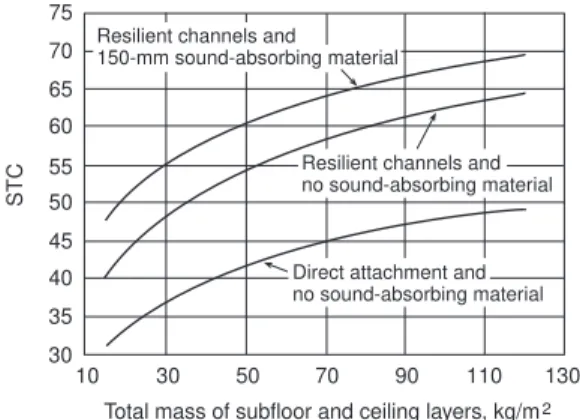
Th e in flu en ce of m ass on STC for floors w ith joists 240 m m d eep an d 406 m m ap art, an d resilien t m etal ch an n els 610 m m ap art is sh ow n in Figu re 2. Th ese th ree cases illu strate th e im p ortan ce of m ass an d of u sin g resilien t m etal ch an n els an d sou n d -absorbin g m aterial in th e floor cavity. Th e grap h is based on th e average resu lts of m an y tests. Ap art from its ed u cation al valu e, it can be u sed to estim ate ch an ges in STC th at w ill occu r w h en th e th ickn ess or n u m ber of sh eets of a m aterial in th e floor or ceilin g is ch an ged . See Table 3 for list of w eigh ts/ area for com m on m aterials.
Figu re 2 sh ow s clearly th at an STC of 50 or m ore can be attain ed w ith a m ass of abou t 20 kg/ m2 an d th at an STC of 55 can be reach ed w ith a m ass of abou t 30 kg/ m2. It is also clear th at w ith ou t resilien t m etal ch an n els or th e equ ivalen t, an STC of 50 can on ly be attain ed w ith a m ass of ap p roxi-m ately 130 kg/ roxi-m2.
Th e research sh ow ed th at p u ttin g sou n d -absorbing material in the cavity of a joist floor w ith a ceilin g th at is d irectly attach ed to th e joists provides no significant increase in sound isolation . Con sequ en tly, on ly on e cu rve (bottom) is shown in the figure for such floors. Figure 1.A generic joist floor. Resilient metal channels support one
or more layers of gypsum board below the joist, which can be of any type. The sound-absorbing material in the cavity increases the sound isolation when resilient channels are present.
Subfloor Joist
Sound-absorbing material Resilient channels Gypsum board
Figure 2.Dependence of STC on total mass per square metre of subfloor and ceiling layers for uni-formly spaced resilient metal channels (610 mm o.c.)
75 70 65 60 55 50 45 10 30 50 70
Total mass of subfloor and ceiling layers, kg/m 2
STC
40 35 30
90 110 130
Direct attachment and no sound-absorbing material
Resilient channels and no sound-absorbing material Resilient channels and
150-mm sound-absorbing material
Furring type 152-mm-thick Layers of STC
glass-fibre batts gypsum
in cavity board No fu rrin g No 1 33 No fu rrin g Yes 1 34 19- x 64-m m w ood No 1 39 fu rrin g, 610 m m o.c 19- x 64-m m w ood Yes 1 42 fu rrin g, 610 m m o.c
22-mm-deep 25 ga. steel Yes 1 43
U-channels, 610 mm o.c.
35-m m concre te on top of sub floor
Non e No 1 46
Non e No 2 47
Non e Yes 1 48
Table 2.STC ratings for floors comprising 38- x 235-mm wood joists (406 mm o.c.), a 15-mm OSB (oriented strand board) subfloor, and 15.9-mm fire-rated gypsum board using different methods of attach-ment, both with and without sound-absorbing material in the cavity.
to th e STC w h en on e m aterial is su bstitu ted for an oth er; h ow ever, for p recise in form ation , it is best to u se m easu red STC ratin gs.
Thick ne ss a nd ty p e of sound -a b sorb ing m a te ria l
Three types of sound-absorbing material were u sed in th e stu d y: glass, rock an d cellu lose fibre. Th e glass fibre an d rock fibre w ere in stalled as batts; th e cellu lose fibre w as ap p lied by sp rayin g in tw o cases, an d by blowing it in as a loose fill in two others. The in flu en ce of sou n d -absorbin g m aterial in th e floor cavity can be su m m arized as follow s: • In creasin g th e th ickn ess of th e sou n d
-absorbin g m aterial in creased th e STC; sim ilarly, d ecreasin g th e th ickn ess d ecreased th e STC.
• Each ch an ge in th ickn ess of abou t 65 m m ch an ges th e STC by 1 p oin t.
• Th ere is som e in d ication th at for th e sam e th ickn ess of m aterial, rock an d cellu lose fibres give an STC th at is h igh er th an th at of glass fibre by abou t 1 p oin t. Th is resu lt n eed s to be verified .
A rra nge m e nt of re silie nt m e ta l cha nne ls
On ly tw o sp acin gs for resilien t m etal ch an n els are com m on ly in u se: 406 m m an d 610 m m . Changing from 610 to 406 mm low ers th e STC by abou t 1 p oin t.
To m ain tain th e fire resistan ce of ceilin gs con sistin g of sin gle layers of gypsum board, additional p ieces of resilien t m etal ch an n el w ere ad d ed to su p p ort th e bu tt en d s of th e gyp su m board . Th ese ad d ition al ch an n els red u ced th e STC by 1–2 p oin ts.
These two effects (spacing and the addition of extra ch an n els) are cu m u lative an d STC valu es in Figu re 2 or Table 4 n eed to be altered to su it th e p articu lar assembly under consideration.
Joist d e p th a nd sp a cing
Increasing the depth of the joists increases the STC, bu t th e effect is not very pronounced. On average, an in crease in d ep th of abou t 100 m m is n eed ed to in crease th e STC by 1 p oin t. In creasin g th e sp acin g betw een joists also in creases th e STC bu t th e effect is even less p ron ou n ced an d very variable. A ch an ge in sp acin g of ap p roxim ately 200 m m w ill ch an ge th e STC by 1 p oin t. Som e sp ecific exam p les in Table 4 fu rth er
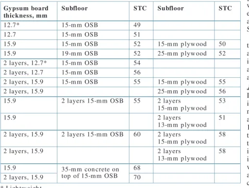
illu strate th e effect on STC of ch an gin g th e total m ass of th e com bin ed floor an d ceilin g. Th e table h as been arran ged to allow com -p arison s am on g floors w ith th e sam e ty-p e of ceilin g bu t d ifferen t su bfloors. It sh ow s th at th e STC ratin gs for assem blies w ith p lyw ood su bfloors are con sisten tly low er th an th e ratin gs for assem blies w ith OSB su bfloors. Wh ile th e p lyw ood u sed w as ligh ter th an th e OSB, th e d ifferen ce in w eigh t alon e w as n ot en ou gh to accou n t for th e measured differences in STC. There are other m aterial p rop erties, su ch as stiffn ess, th at also in flu en ce sou n d tran sm ission . Table 4 provides a general indication of what happens
3
Gypsum board Subfloor STC Subfloor STC
thickness, mm
12.7* 15-m m OSB 49
12.7 15-m m OSB 51
15.9 15-m m OSB 52 15-m m p lyw ood 50
15.9 19-m m OSB 52 25-m m p lyw ood 52
2 layers, 12.7* 15-m m OSB 54
2 layers, 12.7 15-m m OSB 56
2 layers, 15.9 15-m m OSB 55 15-m m p lyw ood 55
2 layers, 15.9 25-m m p lyw ood 56
15.9 2 layers 15-m m OSB 55 2 layers 53
15-m m p lyw ood
15.9 2 layers 51
13-m m p lyw ood
2 layers, 15.9 2 layers 15-m m OSB 60 2 layers 58
15-m m p lyw ood
2 layers, 15.9 2 layers 58
13-m m p lyw ood
15.9 35-m m con crete on 68
2 layers, 15.9 top of 15-m m OSB 70 * Ligh tw eigh t
Table 4.STC ratings for floors with 38- x 235-mm wood joists (406 mm o.c.), 152-mm glass-fibre batts in the cavity, uniformly spaced resilient channels (610 mm o.c.), and fire-rated gypsum board (except where noted)
Material Area w eight,
kg/m2 15-m m OSB 8.8 19-m m OSB 10.3 13-m m p lyw ood 5.7 15-m m p lyw ood 7.1 25-m m p lyw ood 12.1 12.7-m m ligh tw eigh t 7.4 gyp su m board
12.7-mm fire-rated gypsum board 9.1 15.9-mm fire-rated gypsum board 11.3
35-m m con crete 77.0
“Construction Te chnology Up d a te s” is a se rie s of te chnica l a rticle s conta ining p ra ctica l inform a tion d istille d from re ce nt construction re se a rch.
For more information, contact Institute for Research in Construction, National Research Council of Canada, Ottaw a K1A 0R6
Telephone: (613) 993-2607; Facsimile: (613) 952-7673; Internet: http://irc.nrc-cnrc.gc.ca © 1999
Nation al Research Cou n cil of Can ad a May 1999
ISSN 1206-1220
Both of th ese effects sh ou ld be taken in to accou n t w h en extrap olatin g from Figu re 2 or Table 4.
Joist ty p e
For p ractical p u rp oses, th e typ e of joist (solid w ood joists, w ood I-joists, w ood tru sses, an d steel joists) d oes n ot sign ifican tly affect th e sou n d isolation .
Other Findings
• Attach in g th e su bfloor to th e joists u sin g both con stru ction ad h esive an d n ails gave th e sam e sou n d isolation as attach in g it u sin g on ly screw s.
• Changing the gauge of steel joists through a ran ge of 14 to 18 h ad n o effect on th e STC. • Ch an gin g th e w id th of th e I-beam or
tru ss flan ge in con tact w ith th e su bfloor d id n ot affect th e STC.
• Placin g resilien t m etal ch an n els betw een tw o layers of gyp su m board in th e ceilin g sign ifican tly red u ces th e sou n d isolation . Th is con stru ction sh ou ld n ever be u sed w h en good sou n d isolation is im p ortan t (see Figu re 3).
Sound At t e nua t ion in Conc re t e Sla b Floors
Th e sou n d atten u ation p rovid ed by con crete floor slabs is determined mainly by the weight of th e slab. On ly th ree floor slabs w ere measured during the project but the data were su p p lem en ted w ith p u blish ed in form ation to p rod u ce Table 5, w h ich gives typ ical labora-tory STC ratings for a number of concrete slabs. The flow of acoustical energy in buildings, from concrete slabs to the surrounding structure, can be qu ite d ifferen t from th at fou n d in a labora-tory. This can lead to differences in measured sound attenuation for nominally identical slabs for th ese tw o d ifferen t settin gs. Th e exp lan a-tion of th ese d ifferen ces is beyon d th e scop e of th is Up d ate. Th u s, for p u rp oses of com -p arison , it is best to u se laboratory d ata.
A gyp su m board ceilin g su sp en d ed resilien tly below a con crete slab can in crease th e sou n d isolation con sid erably. Th e in crease d ep en d s on th e m ass of th e gyp su m board , th e d ep th of th e cavity betw een th e
gyp su m board an d th e con crete slab, an d th e th ickn ess of th e sou n d -absorbin g m aterial in th e cavity. Th e effects of th ese variables w ere n ot in vestigated in th e p roject. Wh ile little in form ation is available for floors, Con stru ction Tech n ology Up d ate No. 13 p rovid es som e d ata for con crete block w alls th at can be ap p lied w h en ad d in g gyp su m board ceilin gs to con crete floors. As p oin ted ou t in th at Up d ate, a cavity d ep th th at is too sm all can red u ce th e sou n d isolation an d th e STC. In creasin g th e cavity d ep th an d p lacin g sou n d -absorbin g m aterial in it in creases th e sou n d isolation .
I m plic a t ions for t he Const ruc t ion I ndust ry
Th e d ata obtain ed d u rin g th e p roject are bein g u sed to gen erate n ew tables of STC ratin gs for in clu sion in th e Nation al Bu ild in g Cod e of Can ad a.
Re fe re nc e s
1. “Su m m ary Rep ort For Con sortiu m On Fire Resistan ce An d Sou n d In su lation Of Floors: Sou n d Tran sm ission Class An d Im p act In su lation Class Resu lts,” A.C.C. Warn ock an d J.A. Birta, In tern al rep ort IRC-IR-766, Ap ril 1998. 2. Th e p roject w as su p p orted by a con sortiu m th at in clu d ed
Boise Cascad e Corp oration , Can ad a Mortgage an d Hou sin g Corp oration (CMHC), Can ad ian Hom e Bu ild ers’ Association , Can ad ian Portlan d Cem en t Association , Can ad ian Sh eet Steel Bu ild in g In stitu te, Can ad ian Wood Cou n cil, Cellu lose In su lation Man u factu rers Association of Can ad a, Forin tek Can ad a Corp oration , Gyp su m Association , Gyp su m Man u factu rers of Can ad a, Lou isian a-Pacific In corp orated , Nascor In c., On tario New Hom e Warran ty Program , On tario Min istry of Mu n icip al Affairs an d Hou sin g, Ow en s Corn in g Can ad a, Roxu l In c., Tru s Joist MacMillan , Willam ette In d u stries.
Dr. A .C.C. Wa rnockis a sen ior research officer in th e In d oor En viron m en t Program of th e N ation al Research Cou n cil’s In stitu te for Research in Con stru ction .
Figure 3.Resilient metal channels between two layers of 15.9-mm fire-rated gypsum board in the ceiling give this construction an STC of only 38. As shown in Table 4, removing the internal layer of gypsum board gives an STC of 52 for an OSB subfloor. Putting both layers below the resilient metal channels gives an STC of 55.
Subfloor Joist Sound-absorbing material Resilient channels Gypsum board Thickness, mm Mass, kg/m2 STC S olid sla b s 50 115 43 70 160 46 100 230 47 150 350 53 200 460 58 80-150 ribbed 272 51
Hollow -core sla b s
150 220 48
200 280 50
250 310 50