CALCULATION OF EFFECTIVE
ELECTROMAGNETIC PARAMETERS OF
HELIX LOADED COMPOSITES
by
Christina Manolatou
Submitted to the Department of Electrical Engineering and
Computer Science
in partial fulfillment of the requirements for the degree of
MASTER OF SCIENCE IN ELECTRICAL ENGINEERING AND
COMPUTER SCIENCE
at the
MASSACHUSETTS INSTITUTE OF TECHNOLOGY
May 1995
©
Massachusetts Institute of Technology 1995. All rights reserved.
MASSACHUSETTS INSTITUTE OF TECHNOLOGY
JUL 171995
gng.
Auho LIBRARIESA uthor ...
... ...
#..... .
Department of Electrical Engineering and Computer Science
May 12, 1995
Certified by ...
c.~.. .-..
u...
...
Jin Au Kong
Professor of Electrical Engineering
-
"Thesis
Supervisor
Certified by... . ...
...
R. T. Shin
Assistant Grpip Leader, MIT Lincoln Laboratory
\
\ AThesis Supervisor
Accepted by ... ..
•
...
ederic R. Morgenthaler
Chairman, Depa mental Comi *ttee on Graduate Students
CALCULATION OF EFFECTIVE ELECTROMAGNETIC
PARAMETERS OF HELIX LOADED COMPOSITES
by
Christina Manolatou
Submitted to the Department of Electrical Engineering and Computer Science on May 12, 1995, in partial fulfillment of the
requirements for the degree of
MASTER OF SCIENCE IN ELECTRICAL ENGINEERING AND COMPUTER
SCIENCE
Abstract
There is currently a great interest in studying the electromagnetic response of helix loaded composites. There have been many works in the literature that model such materials as artificial chiral media. The objective is to understand the dependence of the electromagnetic response of the artificial medium on the inclusion and the host medium parameters. Therefore, a theoretical model is needed to express this dependence and to be used in the design of composites with desirable absorption and polarization characteristics.
In this work, a theoretical model is proposed for characterizing the response of artificial media made up of randomly oriented helices in a host medium, based on a description of these materials with the constitutive relations of effective chiral media. The macroscopic electromagnetic parameters are calculated in terms of helix and host medium parameters.
The approach taken is to first solve the scattering by a single helix numerically using the method of moments (MoM) under a thin wire approximation in order to calculate the helix polarizabilities. The effective electromegnetic parameters of the composite medium are then obtained by applying an extension of the standard Maxwell-Garnett mixing formula to include chirality. Using the effective electromag-netic parameteters that are calculated by this approach, reflection and transmission calculations are performed.
It is found that the variation of the electromagnetic response with frequency is well predicted by the theoretical model and the expected resonance frequencies are obtained due the accuracy of the method of moments. However, the comparison with published measurement results reveals the limitations of the model to low inclusions and low frequencies.
Due to these limitations an alternate approach is investigated for periodic struc-tures consisting of infinite two-dimensional arrays of aligned helices. This approach
is based on an exact MoM solution of the integral equation for the induced currents, using a periodic Green's function. The formulation derived can be used to find the scattered fields. The reflection and transmission coefficients for a given incidence could then be inverted to give the effective EM parameters.
Thesis Supervisor: Jin Au Kong
Title: Professor of Electrical Engineering Thesis Supervisor: R. T. Shin
ACKNOWLEDGMENTS
I wish to express my sincerest thanks to Professor Jin Au Kong for giving me the opportunity and the priviledge at the same time, to be a member of his excellent research group. I also thank him for his guidance and advice during my first year at MIT.
Many thanks also to Dr. Robert Shin, my thesis supervisor, for his comments and his suggestions but also his encouragement, that have made writing the thesis a lot easier.
I would also like to thank all the members of the EWT group for creating an environment in which it is a pleasure to work and especially Joel Johnson who has helped me a lot with my research since I first came to MIT. My special thanks also to Prathet Tankuranun not only for helping me with the technical details of writing the thesis but also for being a great friend and an always enjoyable company.
I am grateful to my professors at the National Technical University of Athens, but especially to N. Uzunoglu, J. Fikioris and J. Vomvoridis. Their excellent teaching that introduced me to the fundamentals of electromagnetics and their contribution to my being at MIT as a graduate student are greatly appreciated.
I would also like to emphasize how important it is for me to be part of the won-derful community of Ashdown House where I live. I wish to thank all my friends at Ashdown House, for making my life at MIT a happy and unforgettable experience. They have been giving me (each of them in their own special way), the support that I need, to forget the stress and the worries of a graduate student.
My thanks to my parents for encouraging me to come to MIT and for their under-standing since I left home, although they miss me so much. To my family, I dedicate this work.
Contents
Abstract 3 Acknowledgments 5 Dedication 7 Table of Contents 9 List of Figures 11 1 Introduction 131.1 Optical Activity- Chirality ... 13
1.2 Wave Propagation in Chiral Media ... 15
1.3 Artificial Chiral Media ... 19
1.4 Description of Thesis ... 20
2 Reflection and Transmission Characteristics 23 2.1 Introduction ... 23
2.2 Metal Backed Chiral Slab . ... 24
2.3 Chiral Slab in Air ... 27
2.4 Reflection and Transmission Measurements . ... 30
3 Modelling of Artificial Chiral Media 35 3.1 Introduction ... 35
3.3 Chiral Maxwell-Garnett Mixing Formula . . . .
3.4 Conclusion ...
4 Electromagnetic Properties of Helix Loaded Composites 4.1 Introduction ...
4.2 Scattering from Helix ... 4.2.1 Formulation ...
4.2.2 Method of Moments . . . .
4.2.3 Helix Polarizabilities . . . .
4.3 Calculation of the Effective EM Parameters . . . .
4.3.1 Wide Frequency Range . . . . 4.3.2 Narrow Frequency Range . . . . 4.3.3 Sensitivity Study ...
4.4 Conclusions ...
37
40
5 Periodic Helix Structures
5.1 Introduction ...
5.2 General Formulation . . . .
5.3 Two-Dimensional Arrays of Helices
5.4 Three-Dimensional Arrays of Helices
5.5 Summary ...
Bibliography
· · · · · · · · · · · · · · · · r··· 101List of Figures
1-1 Handed objects and their mirror images . ... 14 2-1 Reflection from metal backed dielectric slab . ... 28
2-2 Components of transmitted wave . ... . 31 2-3 Polarization ellipse of transmitted wave showing rotation angle and
axial ratio . . . .. . .. .. . . .. .. . . . .. . . . .. . 32
4-1 Left-handed and right-handed one turn helix . ... 44 4-2 Samples of artificial chiral material (a) isotropic (b) anisotropic . . . 45 4-3 Thin helical wire ... 49 4-4 Helix response (a) maximum current (b) backscattered fields .... . 62
4-5 Free-space experimental setup used in measurements . ... 63
4-6 Relative permittivity: (a)numerical results (b)experimental results . . 65
4-7 Relative permeability: (a)numerical results (b)experimental results .. 66
4-8 Chirality: (a)numerical results (b)experimental results . ... 67
4-9 Medium impedance: (a)numerical results (b)experimental results. .. 68
4-10 Difference of wavenumbers for LCP and RCP: (a)numerical results (b)experimental results ... 69
4-11 Reflection coefficients for metal backed slab of thickness 2 cm for the composite and the host material respectively . ... 70
4-12 Helix response (a) maximum current (b) backscattered fields .... . 73
4-13 Waveguide experimental setup used in measurements . ... 74 4-14 Numerical results for relative permittivity and permeability ... 76
4-16 Reflection coefficients for metal backed slab of thickness 2.14 cm for the composite and the host material respectively . ... 78 4-17 Numerical results for difference of wavenumbers for LCP and RCP and
axial ratio . .. .. .. ... .... ... .. .... .... 79
4-18 Experimental results for rotatory dispersion and axial ratio ... 80
4-19 Effective EM parameters calculated at 10 GHz varying conductivity and pitch-to-radius ratio ... 82
4-20 Effective EM parameters calculated at 10 GHz varying conductivity and pitch-to-radius ratio ... 83
Chapter 1
Introduction
1.1
Optical Activity
-
Chirality
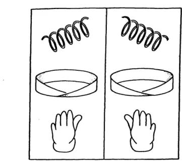
Optical activity has been known since the 19th century. Pasteur, or isotropic chiral, materials have long been distinguished by their ability to rotate the plane of polariza-tion of light passing through them. Arago (1811) and Biot (1812) discovered the first effects of optical activity in anisotropic gypsum and quartz crystals. These discover-ies led to the problem of determining the cause of optical activity. In 1848 Pasteur solved the problem by postulating that the optical activity in a medium is caused by the chirality of its molecules [14]. Chiral materials display handedness (from where the term chiral which means handed, comes) in their microstructure which denotes a lack of space inversion symmetry. That is, they exist in two distinct forms, mirror images of each other, that cannot be superimposed (stereoisomeres or enantiomeres). Chirality is a purely geometric notion which refers to the lack of symmetry of an object. By definition, an object is chiral if it cannot be brought into congruence with its mirror image by translation or rotation. Most of the work on chiral media has been done by physical chemists who have developed polarimetric techniques to investigate molecular and crystall structures. But chirality is a phenomenon which can be found in everyday life. Helices, M6bius strips, and, of course our hands are examples of chiral objects found everywhere (Figure 1-1). The rotation of polarization of linearly polarized light passing through a substance whose molecules possess a
Figure 1-1: Handed objects and their mirror images
certain handedness, such as sugar, is the most familliar of the various chiral effects that occur in nature. Optical rotation and circular dichroism for example is exhibited
by certain molecules, such as L- and D-type stereoisomers. As the name suggests, such
phenomena are noticeable at optical wavelengths (400 - 700 nm). Due to the right- or
left- handed configuration of their molecules, such media can distinguish between right and left circularly polarized waves in the visible range. When an electromagnetic wave travels through a medium consisting of chiral molecules it is forced to adapt to the handedness of the molecules. In such media, the linearly polarized light decomposes into two circularly polarized waves.
The rotation of the polarization plane is the manifestation of circular birefringence, which is the difference in the refractive indices for left and right circularly polarized electromagnetic waves. Chiral effects which have proved useful in molecular structure determinations are circular dichroism (the differential absorption of right and left circularly polarized light if the medium is lossy), optical rotatory dispersion (the dependence on the frequency of the angle of rotation of the plane of polarization) and
circular intensity difference (the difference in scattered intensity between right and left circularly polarized light incident on the medium) [16]. Also, the Cotton effect, is rapid variations of the angle of rotation and the attenuation with frequency.
a66~~
'N
The effects of optical activity are observed when the wavelength is small enough to discriminate the handedness of the chiral particles. Thus, substances which are op-tically active in light wave frequencies are inactive in microwave and millimeter wave frequencies. However, the analog at lower frequencies can be artificially constructed. Drude was the first to suggest constitutive relations for optically active media. The measure of optical activity in these relations can be called chirality parameter and contains information also for the circular dichroism.
1.2
Wave Propagation in Chiral Media
Because a chiral medium responds differently to an electromagnetic excitation, de-pending upon the handedness with which it is endowed, its contitutive relations are not the usual ones. The constitutive relations D = eE and B = ,uH are not compat-ible with the phenomena of birefringence and dichroism. Within the framework of classical electromagnetics, the optical rotary dispersion and circular dichroism prop-erties of chiral materials can be explained by a magnetoelectric coupling effect [9]. That is, the effective polarization density P, (effective magnetization density P,,) is induced not only by the electric (magnetic) field but also on the magnetic (electric) field. Thus, a chiral medium is described by constitutive relations in which the elec-tric and the magnetic fields are coupled. That is the elecelec-tric and the magnetic flux density are induced by both the electric and the magnetic fields. Several forms exist in the literature for the constitutive relations for isotropic chiral media. A notation commonly used in the literature (Drude-Born-Fedorov relations [9]) is:
D = eE+ Vx E (1.1)
B = iH + P 1 V x H (1.2)
These relations reflect the isotropic but non-centrosymmetric nature of the materials via the terms V x E and V x H [24]. The scalar material constants 6 and /I are the dielectric permittivity and the magnetic permeability of the medium, respectively.
The scalar constant P (with units of length) is the chirality parameter and has a positive real part if the medium is right handed and a negative real part for left handed medium. Because chiral media are reciprocal bi-isotropic media the coupling between the electric and the magnetic field is described by the same parameter. Thus a chiral material is characterized by three complex, frequency dependent properties. It may be readily observed that because chirality is manifested through the terms V x E and V x H, it is absent for static or even quasi-static fields.
In optical frequencies, it is expected that P will be a very small quantity around 10-10m. However the origins of a nonzero 8 are not necessarily molecular. Electro-magnetic waves can recognize the handedness of a chiral objet primarily due to their transverse nature. Thus, at microwave frequencies the chirality parameter can be as big as 8 _ 10-3m, since it is possible to introduce much higher volume fractions of the chiral microstructure [26].
An alternate but equivalent notation is [9]:
D = E' + i,/JV- (1.3)
=
-i
- i_eo
/
(1.4)
where n is the chirality parameter and is dimensionless.
The relations between notations (1.1), (1.2) and (1.3), (1.4) are:
e' = (1.5) 1 - w2pep2
' =
(1.6)
= w#e,3 (1.7) and: E = e' 1 2 (1.8) r2= '( 1 (1.9)koP = (1.10)
where n = 7 oIT/•-/Eo and ko = w Eo/-o.
Using a decomposition first proposed by Bohren [4], it can be shown that left and right circularly polarized fields are the eigenstates of polarization that propagate with a different phase velocity and attenuation. The constitutive relations (1.1), (1.2) in conjunction with Maxwell's equations for source free space:
VxE = iwB (1.11)
Vx H = -iwD (1.12)
V-B = o(1.13)
V.D = 0 (1.14)
give the equations:
V.
[ .]H
=[K]
2 (1.15) where the matrix K is given by:1
[k
2/ iwL][K] =
1
-k202
-iwE
k
(1.16)
k
20where k = wV/ic and a e- iwt time dependence is assumed. The fields in such a medium also satisfy the equations:
Vx [ = [K]_H (1.17)
SE 0
The (1.18)
equation. A linear transformation of the electromagnetic field:
= [A)-]QL -
(1.19)
diagonalizes K:
[A] = [A]-' [A] [A]
(1.20)
where
kL
0
[A]= 0 kRJ
(1.21)
aR[A] =[
R
(1.22)
a, 1 wherek
=
k
(1.23)
kk
=
(1.24)
and .k(1 1- t l2'2 2 aR = -Z=-i (1.25) S.kL(1 -/ 2W2qL) 2 fW 2qL ia
= -
h
= -
(1.26)
W/1 77The waves QL and QR are the eigenvectors or the characteristic polarizations of the medium and satisfy the equations:
[QL [ 0
[
+
_
+
=
(1.27)
LQRJ
0 kL QR 0QR
k 0
Q o
Vx
=
kL
[
(1.28)
xQR
0 -kR
QR
[
QLV
[01
(1.29)
QR a right hand circularly polarized (RCP) wave propagating with wavenumbers kL
and kR, respectively. Hence the left and right handed CP waves travel with different phase velocities and this gives rise to the rotation in the plane of polarization when linearly polarized light passes through the medium. The LCP waves travel faster than RCP waves inside the left handed medium and vice versa. If, in addition, the medium is lossy, that is k is complex, the two eigenwaves will experience different attenuation resulting in an elliptically polarized wave with a rotation of the major axis of the ellipse (dichroism).
1.3
Artificial Chiral Media
While optical activity occurs in nature in certain materials at optical frequencies, the analog at lower frequencies is artificially constructed. Such materials could be de-scribed as artificial chiral media. These media also exhibit, typically in the microwave region, the phenomena of optical activity mentioned above (circular birefringence, ro-tatory dispersion, and circular dichroism). The discovery of such a phenomenon is attributed to Lindmann (early 1900's) [12],[13] who measured the rotation of the plane of polarization for a collection of wire helices in the wavelength range 12 to 34 cm. It was found that a collection of randomly oriented right-handed helices would rotate the plane of polarization of a linearly polarized wave one way but that a similar collection of left-handed helices would rotate the plane of polarization the opposite way.
Since chirality is related to handedness and handedness is related to optical ac-tivity and since electromagnetic waves can discriminate between objects of different handedness owing to their transverse nature, it is not surprising that the interaction between an electromagnetic wave and a collection of randomly oriented chiral objects can be such as to rotate the plane of polarization of the wave to the right or to the left depending on the handedness of the objets. That is, effectively chiral me-dia can be constructed by embedding chiral microstructures in a host medium. The microstructure should be large enough that the electromagnetic wave in the matrix
can appreciate its handedness; at the same time the microstructure size should be small enough that the composite medium, consisting of a chiral phase is effectively homogeneous but chiral [18],[23].
In recent years interest has grown in understanding the properties, at microwave frequencies of chiral composites comprising conducting chiral objects such as helices embedded in a dielectric host medium. Guire et al. (1990) [21] measured the rota-tory dispersion for artificial chiral composites, which were made by embedding small helices in a nonchiral host medium. They reported that the rotation angle was pro-portional to the volume concentration of the helices. Besides the rotatory dispersion, the reflection characteristics from metal backed chiral composites were also reported and it was concluded that a distinct difference in both the rotation and the reflection characteristics can be observed between chiral and nonchiral composites. This work appears to support the theoretical modeling work of Varadan et al. (1987) [22], which predicted that chirality in a material not only affects the polarization characteristics of a propagating wave, but also affects the reflection, transmission, and attenuation characteristics.
By varying concentrations and the sizes of chiral inclusions, the properties of the
composite medium may be altered to suit desired polarization characteristics. Chiral composites can also be attractive as highly efficient absorbers. These absorption char-acteristic are attributed to multiple scattering in conjunction with mode conversion from right to left hand polarized waves [26].
1.4
Description of Thesis
In Chapter 2 the transmission and reflection for chiral media are studied, based on the principles of wave propagation presented in this chapter. The effect of chirality in enhancing the absorption by a low loss dielectric material is examined by calculating the reflection coefficients for a chiral slab over a perfect conductor. The transmission coefficients for a chiral slab in air are also derived and the effects of optical activ-ity (rotation of polarization and dichroism) are related to the effective parameters
through a general measurement technique.
In Chapter 3 the modelling of artificial chiral media is discussed. The standard Maxwell-Garnett mixing formula and its extension to effective chiral media, are pre-sented and the assumptions and limitations inherent in this formula are reviewed. Chapter 4 presents the modelling work. The problem of electromagnetic scattering by a single helix is solved numerically using a method of moments (Galerkin's method) for the induced currents under a thin wire approximation. Then, the equivalent electric and magnetic dipole moments are calculated and the helix polarizabilities obtained as scalar quantities by averaging over orientation and spin of helix. The Maxwell-Garnett mixing formula is then applied to give the effective EM parameters. Reflection and transmission calculations are also performed and our theoretical pre-dictions are compared to published results. A sensitivity study is also performed and finally the accuracy of the model used is discussed.
Due to the limitations of the Maxwell-Garnett mixing formula to low frequencies and low chiral inclusions, another approach will also be investigated in chapter 5. This is based on a method of moments solution of the exact integral equation for a medium made up of periodically spaced helices. The periodic properties of the medium allow a reduction of the scattering problem to that of a single helix with the use of the periodic Green's function. Our objective in this case is to obtain the effective EM parameters by inversion of reflection and transmission coefficients from a layer of finite thickness.
Chapter 2
Reflection and Transmission
Characteristics
2.1
Introduction
The reason that wave propagation and scattering characteristics are so different in chiral media is attributed to mode conversion from LCP to RCP and vice versa. The induced surface current and surface charge densities at the boundary of a chiral ma-terial are quite different of those in a non-chiral mama-terial [2]. An incident linearly polarized wave will give rise to LCP and RCP inside the inclusion made of chiral material, and these fields propagate with different velocities. Hence if there are sev-eral interfaces between chiral and nonchiral materials, we expect enhanced multiple scattering due to mode conversion, and if the host material or inclusion is lossy, this would lead to increase absorption of the wave as it undergoes multiple scattering. Thus, chiral composites can be attractive as highly efficient absorbers. For example, it can be shown theoretically that by endowing low loss dielectric composites with chiral properties the reflected power can be cut down by a factor of 4 or more for the case of a plane coating on a perfectly conducting surface [22].
The field transmitted through a chiral composite layer is elliptically polarized for a normally incident, linearly polarized wave. The major axis of the polarization ellipse is rotated with respect to the polarization of the incident wave. The ellipticity is
positive when the LCP wave is more absorbed than the RCP wave and the transmitted field is right elliptically polarized. Otherwise the transmitted field is left elliptically polarized.
In this chapter the reflection and transmission coefficients for a chiral slab of given thickness are derived and then used to determine the electromagnetic properties of a chiral sample based on transmission and reflection measurements.
2.2
Metal Backed Chiral Slab
Consider first the case of general oblique incidence on a chiral slab which occupies the region 0 < z < d. The region z < 0 is free space while the plane z = d is assumed
to be perfectly conducting. This geometry describes a metallic surface coated with a chiral layer of thickness d.
The incidence wave is:
- = (AH cos o00 + AE^ - Ar sin Oo) exp [iko (sin Oox + cos Ooz)] (2.1)
W1
H- VxI7
iwjuo
where AE
#
0, AH = 0 refer to TE polarization while AE = 0, AH#
0 refer to TEpolarization.
The reflected wave obeys Snell's law of reflection but is composed of two circularly polarized waves. On the other hand, two distinct wavenumbers exist in the chiral medium giving rise also to two circularly polarized waves, (left handed and right handed) which propagate with different phase velocities in the chiral medium. Each, however, still obeys Snell's law of refraction and is therefore inclined differently to the chiral-achiral interface [2]. Consequently, the power reflected by such an interface is quite different from that which can be calculated quite easily by ignoring the handedness.
The reflected wave is:
= (-RTMAH cos 0o' + RTEAEY + RTMAH sin 9o0) exp [iko (sin 90o - cos 00z)]
(2.2)
S 1
H = Vx E
iwIo
where RTE and RTM are the reflection coefficients for TE and TM polarization, respectively.
The eigenwaves propagating in the chiral layer are the sum of a forward and a backward travelling waves:
QL = AL exp [ikL (sin9L +cos9OLzl + BL exp [ik (sin9LX - cs 9z'] 0~ (2.3)
R R LR R RRJ R L R R RR J
where 9 L denote the angles of inclination for the LCP and RCP waves.
R
The polarization of QL is derived using the equations (1.28):
R ikL X QL = ±kLQL R R R R
(2.4)
thus: QL R that representAL (cosOL + i- sin9L) exp [ik (sin±xi + cos rZz)]
' •(2.5)
BL
(cosOL^
I-sin^
•
exp [ik (sin9•
-cosz)]
(2.5)
a superposition of forwards and backwards t R Rcularlya superposition of forwards and backwards travelling circularly polar-
polar-ized waves.
The fields in the chiral medium are:
Ech =
Hch =
QL + aRQR aLQL + QR
where aR = iy, aL = i/! and q = /;/.
Next, we apply the boundary conditions at the intefaces and phase matching:
(2.6)
(2.7)
x.
(
+ V
-
Fch)
.
+
+
~
-
-h
)
-.
(V
+
- Ech) y -(I
+R
- ies) at z = d: -EchPhase matching: ko sin Oo = kL sin OL R R = 0 = 0 = 0 = 0 = 0 = 0
-o
-o
(2.8)
(2.9) (2.10) (2.11)(2.12)
(2.13)
Thus we get a 6 x 6 system of equations which can be solved for the reflection coefficients RTE, RTM:
TE polarization:
RTE - [cos(kL
cos OLd) + cos(kR COS ORd)] + i-•- cos o rsin(kL Cos Ord) +
[cos(kL
cos
OLd) +
cos(kR cos
ORd)]
-
i
•
cos
o
sin(kL
COB OLd)+
sin(kI COSOyd)] cos OlR sin(kR COs 0Rd) cos R J
(2.14)
TM polarization:[cos(kL
coS
OLd)
-. cos(klR
co S
Rd)]
+
i
-coS
s•in(kL
COO
,d) _
7 L COS OL
[cos(kL cos OLd) - cos(kR cos 8Rd)] - i cos 0 sin(kL COS Ld)
sin(kR cos OGd) cos J1R
(2.15)
In the case of zero chirality 0 L = 0 and kL = kR = k, thus:R
RTE
RTM
1 + i- c"e tan(k cos Od)
1 - incos• tan(k cos Od) 1 0 co tan(kcosd)
1
+ i .co" tan(k cos Od)
,q
COS
aU~LI~VVI
at z = 0: RTM -1 - i c" s0 tan(k cos 8d) r7 cos 0
(2.16)
(2.17)
In the case of normal incidence the above expressions reduce to:
1 + i-- tan (kL+lcd)
RTE = RTM= 1o 2 (2.18)
1
- i-
tan
kr
dkg
As an example we show the results for the case of metal backed chiral slab of thickness
d = 2 mm at frequency 100 GHz (figure 2-1). The power reflection coefficients for TE and TM incidence are plotted as functions of the angle of incidence. The dielectric constant is taken e = (5 + iO.1)Eo while the chirality 3 is varied from 0 to the order of 104. These cases are examined, among others, in [22].
As can be seen in the plots, in the case of real 0 the reflection coefficients are considerably lower than for an achiral lossy dielectric, while a complex P does not seem to contribute in the reduction of the reflection. In addition, chirality does not have any effect in reducing the reflection if the coating is lossless.
2.3
Chiral Slab in Air
Following the previous analysis, in the case of normal incidence, we can calculate the reflection and transmission coefficients for a chiral slab occupying the region 0 < z < d
in free space. For a normally incident plane wave the reflected wave will be linearly polarized in the same direction, while the transmitted is elliptically polarized. Thus it has a copolarized and a crosspolarized component with respect to the incident wave. With the copolarized components are along the z- direction, we have:
Incident wave: - = &eikoz (2.19) . =
e
ikoz (2.20) Reflected wave: E = = Re- ikoz (2.21)Power Reflection Coefficient b=0.0 m
b=0.0002 m
b=0.0002(1+i) m
angle (deg)
Figure 2-1: Reflection from metal backed dielectric slab
1 0.5 0 0.5 0.5 0 .... TM , i | I i J
-H
=
-yRe
-ikoz
(2.22)
Transmitted wave:
Et = 5:TcoeikOz +
+Tcreikoz
(2.23)H
= (Tcoeikoz
Tcrekoz)
(2.24)
Eigenmodes in chiral slab:
ikL z -ik L Z
QL = AL (ii) ef + BL (x i) e 1 (2.25)
R R
Fields in chiral slab:
Eh
=
QL
+
aRQR
(2.26)
ch = aLQL + QR (2.27) Boundary conditions: at z = 0:x.(r7
+ -
ch)
= 0
(2.28)
~- +
'
-
(2.29)
S(-+ Ei rch) _- = 0 (2.30) = op+jHr - wc 0 (2.31) at z = d: ( (ch _ t) = 0 (2.32) (-ch _ t = 0 (2.33) SEch Et) = 0 (2.34) " (Rch -t = 0 (2.35)Thus:
r2 - 72
27R
=2 c0 cos( kkd) - i(72 +
qo)
sin( d) (2.36)and
T = T cos(k L - kR d) (2.37)
kCL - kR
Tc = -Tsin( 2 d) (2.38)
where To, Tc, are the transmission coefficients for the copolarized and the crosspo-larized components of the transmitted wave, respectively and
T = (2.39)
2r0o cos(k ~kL kd) - i(r'2 + 7r0) sin( kL+kd)
2.4
Reflection and Transmission Measurements
The theory for plane wave transmission and reflection serves as a basis for calculating the material parameters from measurements of the electromagnetic response of a chiral slab. The experimental data are usually in the form of complex reflection and transmission coefficients. For slab measurements at the normal incidence, it appears possible to find the material parameters by direct inversion of the reflection and transmission coefficients [5],[21].
As we have seen, the reflected and transmitted waves for a planar chiral sam-ple are linearly and elliptically polarized, respectively for normally incident linearly polarized waves. Therefore, one reflection measurement is enough to describe the reflected field and two transmission measurements at different polarization angles are needed to fully determine the transmitted polarized wave. Thus, the transmission measurements can be broken down into two orthogonal components that are copolar-ized and crosspolarcopolar-ized, respectively, with respect to the incident linearly polarcopolar-ized plane wave. The real part of the chirality parameter can be determined through the angle of rotation 0 between the polarization direction of the incident electric field and the direction of the major axis of the field polarization ellipse. On the other
Figure 2-2: Components of transmitted wave
hand, the imaginary part of chirality is related to the ellipticity of the polarization ellipse. These angles can be determined if the transmitted field has been measured at two angles by rotating the receiving antenna, because these complex measurements determine the ellipse of the wave.
The S parameters are used to denote the reflection and transmission coefficients.
S11 is the reflection coefficient, S21 is the transmission coefficient, while the subscripts
co and cr are used again to denote the copolarized and crosspolarized components,
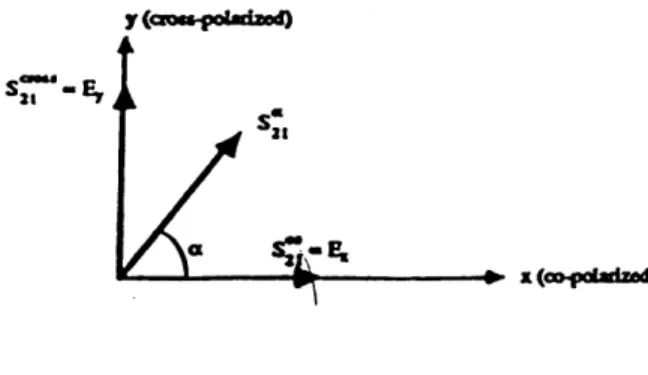
respectively. The transmission at an arbitrary angle a with respect to incidence is denoted by S2 1. Therefore (Figure 2-2):
S21, - S21c COS a(2.40)
s2 1cr, = sina(2.40)
Theoretically we can relate the S parameters for linearly polarized incident waves to those for LCP and RCP polarized waves in combination with (2.37), (2.38) using the relations: S11 = S11R = SilL (2.41) S21R = S21,o + iS, 21 = Te L d (2.42) S21L = S21- S21c, =Tei 2
(2.43)
S21R ei(kL-kR)d(2.44)
S21Lwith kL = k' + ik" . The Stokes parameters can be used to find the angle of R R R
Cass-poladrizd
B
A/B - Axia Rato (AR)
A Roatioo Angl (0)
cAPOlariand
Peopagation ot oof paper
Figure 2-3: Polarization ellipse of transmitted wave showing rotation angle and axial ratio
rotation and the ellipticity of the polarization ellipse (Figure 2-3). Assuming that the polarization of the incident wave is in the x-direction it can be seen in Figure 2-2 that
S21co = E, (2.45)
S21, = Ey (2.46)
Therefore the Stokes parameters in combination with (2.37), (2.38) give:
So = EE + EE* = IT12 cosh[(k" - k")d] (2.47)
S, = EE - EE* = ITI2 cos[(k' - k )d] (2.48)
S, = -2ReEE = IT12 sin[(k' - kj)d] (2.49)
S3 = 2ImE,E = IT 2 sinh[(k" - kj)d] (2.50)
The rotation angle 0 can be found from (2.48), (2.49) as:
1 (S) k' - k2
0 = - tan- 1 -- d nw (2.51)
2
S,
2
The ambiguity for 0 can be removed by another measurement with a different thick-ness sample which determines n.
as:
B
tan
B,=
A
(2.52)
and can be found from (2.47), (2.50) is given by:
= sin-1 S sin- {tanh[(kZ - k")d]} (2.53)
2 \So 2
The ellipticity can be measured through the axial ratio AR which is the ratio between the major axis and the minor axis of the ellipse and is therefore given by:
AR = (2.54)
tan Ik
For the axial ratio we have: 1 < IARI < oo, with 1 for circular polarization and oo for linear polarization. In general, AR > 1 corresponds to right elliptical polarization, while AR < 1 corresponds to left elliptical polarization.
From transmission measurements the real and imaginary parts of the chirality can be determined independently from the other two material parameters as can be seen in (2.51) and (2.53). On the other hand, we cannot determine the permittivity and permeability without knowing the chirality value. Provided that the chirality has been measured, the other two parameters can be determined from the reflection measurement combined with the copolarized transmission data. In the inversion algorithm there are again multiwavelength ambiguities expressed by integer numbers, and can be removed by repeating the measurement at another frequency or slab thickness.
The available experimental results for the electromagnetic properties of chiral composites that are used for comparison with the theoretical predictions are similar measurement procedures [25],[15].
Chapter 3
Modelling of Artificial Chiral
Media
3.1
Introduction
When an electromagnetic wave propagates through an artificial medium it induces currents on the scatterers it includes. The scatterers can be viewed as equivalent electric and/or magnetic dipole moments that modify the net electric and/or mag-netic dipole moments per unit volume, thus modifying the effective electromagmag-netic parameters of the medium [10]. An interesting and useful feature of artificial media is that by adjusting the size, shape and density of the scatterers it is possible to
construct a medium with different electromagnetic properties.
For composite chiral media, the determination of the polarizability of the chiral inclusions is the first step in the modelling of heterogeneous complex materials in the case of weak mixtures. The polarizability components express the dielectric, magnetic and magnetoelectric responses of the inclusion element, and once these are known, it is possible to characterize mixtures that are composed of these inclusions embedded in a host medium using a quasistatic theory to derive mixing formulas involving the polarizabilities. The macroscopic parameters depend, in addition to the polarizabilities, on the fractional volumes of the components making the mixture. Since the analysis has been based on quasistatic assumptions, the mixing rules are
restricted by it. Therefore, the limitation of the formulas used so far is that the size of the inclusions has to be much smaller than the wavelength. A limit is that the size parameter kejjd is less than 1, where d is the average diameter of the particle and
kq,f is the wave number within the mixture [9].
3.2
Standard Maxwell-Garnett Mixing Formula
The simplest mixing rule is the Maxwell-Garnett formula which gives the effective permittivity eqf of a dielectric medium where spheres of permittivity E occupy a volume fraction f in a host medium of permittivity ;o :
E - eo
Eeff = co + 3fEo E - (3.1)
i + 2Eo - f(E - o)
The Maxwell-Garnett formula can be derived from the following independencies. The effective permittivity gives the relation between the electric field and the average electric flux density:
(D) = eyffE = ioE + (P,) (3.2)
The average polarization is the dipole moment density:
(PT) = nope (3.3)
where no is the number density of the electric dipoles. The electric dipoles are
deter--L
mined by the electric polarizability a and the field exciting the inclusions: p. = aE.
The exciting field EL also called Lorentzian field, is larger than the average field B because it includes the contribution from the surrounding polarization:
EL = E + (3.4)
The combination of these conditions yields the dielectric mixing rule. The effective permittivity in terms of the polarizability, is given by the Lorenz-Lorentz formula.
ff = o + 1
a
(3.5)
3eo
3.3
Chiral Maxwell-Garnett Mixing Formula
Using an extension of the standard Maxwell-Garnett mixing formula to the case of an effective chiral medium [7], the effective electromagnetic parameters that appear in the macroscopic constitutive relations, can be expressed in terms of the polarizabilities of the chiral particles embedded in the host medium. This mixing law is based on the quasistatic analysis of scattering by a chiral sphere and is therefore valid at low frequencies. So the assumptions made in this approach are:
- The inclusions are spherical chiral particles
- The size of the inclusions is small compared to wavelength
- The spheres are non-interactive.
Consider a mixture made up of an achiral background with permittivity eo and perme-ability lio which includes no spherical chiral scattteres per unit volume. The composite medium is described by the constitutive relations of an effective chiral medium:
(D) =
Fe,ffi
+ iejfN1j,,
HIj
(3.6)
(R)
= ILeff- 9,r,,ff
•I-
i(3.7)
Also:
(D) = o
+
(P,,) + (Pem,,)
(3.8)
where P,, and Pem are the electric dipole moments per unit volume induced by the electric and the magnetic field, respectively, while P,i, and Pmi are the magnetic dipole moments per unit volume induced by the electric and the magnetic field, re-spectively. These are related to the dipole moments of a single scatterer as:
(Pij) = no7pj (3.10)
where i, j denote any combination of e and m. The dipole moments are proportional to the exciting (Lorentzian) fields:
,e = a~~gL (3.11)
&m = ac4mHL (3.12)
where ae, and aCm, are the polarizabilities of the scatterer and ý is either e or m. The exciting fields EL and HL are given by the quasistatic analysis of scattering from a sphere, in terms of the average fields E and H as:
LE = + (3.13)
-L P
H =H + (3.14)
31to
Using the relations (3.10), (3.11) and (3.12), the total electric and magnetic dipole moments per unit volume Pe and Pm, respectively, can be written as:
PC
=
noa,,Ee
+
nea,
L
(3.15)
Pm
= noai,EL + nooammHL
(3.16)
(3.17)
and in combination with (3.13) and (3.14) we get:1 oae - oem = noaE
+
noaemH (3.18)noame
( noamm
- P. + Pm = noammE + noammH (3.19)
Solving the system of 3.18, 3.19 for Pe and Pm, in terms of the fields and the
polar-izabilities, the following expressions for the effective parameters are derived:
(1
-
noamm/311o)
noae, +
naem,,c,,
/3o1
ef f = 6o+ A (3.20)
(1
-
noaee/3eo)
noamm
+
n,,aem•
e,/3eo
ef f = Po+ A t m(3.21)
s noam
i
ne0meneff = -A -Vfi A (3.22)
where
A
=
(1 - noaee,,/3o) (1
-
noamm,/31o)
-
n a,,,ame,/9ioEo
Using the expressions for the polarizabilities as given by the quasistatic analysis of scattering from a chiral sphere with radius a, permittivity e, permeability pL and
chirality
K[8]:
ee
47ra (A +
2Ao)(E
-
eps - -
oo(3.23)
B,,
=~
4
G
,n
(3.23)
i3npo o
am,, = 4ira3 Oo O (3.24)
MM
4ra
3(
-
Po)(E + 2epso) -
2o
(3.25)
am
=
4TG3Po
(3.25)
3 - i 31CIL°C°
ame = 4ra3 00I3 B 0 (3.26)
with B = (i + 2Po)(E + 2Eo) - 12 00EO, equations (3.20), (3.21) and (3.22) become:
(e - Eo)[(P + 2Po) - f(P - po)] - C2UO2o(1 - f)
Eeff = o 3f Eo C (3.27)
(3f - po)[(E + 2Eo) - f(e - co)] - /oo(1 -
(f)
Pef! = Ao 3f o C (3.28)
ne - C C (3.29)
where f is the fractional volume of the chiral inclusion phase of the mixtures and
C = [(p + 2Poo) - f(f -
(oo)][(E
+ 2Eo) - f(E - co)] - K2It is easy to check that the above mixing rules satisfy all the requirements saddled on a tentative mixing formula:
- for f = 0, the permittivity and the permeability are those of the background medium while the chirality vanishes
- for f = 1, the effective parameters are those of the inclusion phase
- if the chirality of the inclusion phase vanishes, the effective chirality vanishes and the formulas reduce to the standard Maxwell-Garnett mixing formula
One impressive aspect about the chiral Maxwell-Garnett mixing formulas is the set of multiple dualities in the macroscopic expressions: The way the permittivity e of the inclusions affects the effective permittivity eeff, chirality ,ef f and permeability
pff is the same as the way the permeability u of the inclusions affects the effective
permeability Ipeff, chirality cff and permittivity eeff.
It is important to observe that the effective permittivity and permeability of a mixture are even functions of the chirality of the inclusion phase. Hence the sign of handedness should not have effect on these parameters, and they are scalars, invariant of space inversion. This is because samples of media that are mirror images of one another should have the same permittivity and the same permeability. Although in the subatomic level, in the weak interaction process, the asymmetry between left and right has been predicted and experimentally observed one should expect this not to happen at the macroscopic level where racemization processes tend to eliminate handed effects [9].
The effective chirality parameter is an odd function of the chirality of the inclu-sions. A change in the handedness of the component changes the handedness of the mixture.
3.4
Conclusion
Both standard and chiral Maxwell-Garnett formulas are limited to low frequencies. That is, the scatterers must be sufficiently small compared to the wavelength, so
that quasistatics can apply. The Mawell-Garnett mixing law is also valid only for low inclusions since it ignores the scattering loss which becomes important at higher concentrations.
This approach under the assumptions made above can be applicable to the case of chiral particles of any shape, for example miniature helices. Since the scattering behavior is strongly dependent on the size of the particles, objects with dimensions comparable to the wavelength require more complicated treatment than small inclu-sions, and the Maxwell-Garnett formula is no longer accurate.
Chapter 4
Electromagnetic Properties of
Helix Loaded Composites
4.1
Introduction
Helices are perhaps the most common chiral (handed) objects found in nature. A helix can be either left-handed or right-handed (Figure 4-1). The one turn helix is the canonical three-dimensional chiral structure [18]. A helical wire on a uniform cylinder becomes a straight wire when unwound by rolling the cylinder on a flat surface. Viewed end-on, a helix projects as a circle. Thus, a helix combines the geometric forms of a straight wire, a cylinder and a circle. The dimensions of a helix are conveniently represented by either pitch P and circumference C, or the length of one turn L and the pitch angle a. When the pitch is zero then a = 00 and the helix becomes a loop. When the diameter is zero then a = 900 and the helix becomes a linear conductor. It is noted that there is no chirality when a = 00 or a = 900 because, in these two limits, there is no handedness.
The magnetoelectric coupling can be intuitively grasped from the behavior of a helix as it is exposed to the electromagnetic field. If an electric field excites the helix, it separates charges, creating an electric dipole moment. This contributes to the permittivity of the composite medium, but the shape of the helix forces the charge to move along a circular route, in addition to the linear path. This electric current loop
Figure 4-1: Left-handed and right-handed one turn helix
is equivalent to a magnetic dipole, and if all the helices in a mixture have the same handedness, the magnetic polarization effect will be enhanced. The corresponding appearance of both types of both types of polarization results also for magnetic field excitation.
It is interesting to study what is the electromagnetic effect on a given left-handed or right-handed structure. A specific helix should scatter differently to an incident left-handed wave compared to a right-handed wave. The objective is to predict the effective permittivity, permeability and chirality of a medium, knowing the dimensions and the concentration of helices embedded in the sample.
To secure isotropy, helices must be randomly oriented so that there is no pre-ferred direction (Figure 4-2a). If the helices are set in arrays in alligned configuration the result is a macroscopically bianisotropic material, leading to dyadic (or matrix) coefficients in the constitutive relations (Figure 4-2b).
In practice, any method of making an artificial chiral medium will affect all the medium parameters (dielectric, magnetic and chiral), together. Thus to investigate
(a)
(b)
the possible effects, one must start from detailed analysis of the chiral objects. We then include all the effects of the actually adjustable physical parameters, rather than varying a chirality which cannot be independedly adjusted. Such an analysis is performed here for a chiral composite medium containing metal wire helices, which have been used in many published works. The electric and magnetic moments of the helix are calculated using the method of moments. These are then used to find the electromagnetic properties of the composite medium using the Maxwell-Garnett mixing for effective chiral media.
4.2
Scattering from Helix
Starting from the study by Jaggard et al. [6] there has been work on a quasistatic ap-proach to the modelling of helix scattering. In these investigations the polarizabilities of the helix are calculated as functions of the static capacitance and inductance of the straight portion and loop of the helix, and the crosspolarizabilities are connected with the copolarizabilities. As the polarizability matrix elements are known, the effective parameters can also be calculated using some mixing formula. The problem with the early models has been the narrowband character of their validity around the resonant frequency of the helix.
To attack the electromagnetic problem involving chiral geometries, one needs to write boundary conditions on handed surfaces. The formulation of these conditions on a helix surface leads to a problem with greater analytical difficulties than in the corresponding nonchiral geometries. Therefore no analytical solutions for the helix scattering problem exist. However, numerical and approximate efforts in the literature are numerous [3].
4.2.1
Formulation
The currents induced on a helix are calculated, using a method of moments (Galerkin's method) to solve the electric field integral equation (EFIE) under a thin wire approx-imation. In order to use a thin wire approximation, the wires under consideration are
assumed to be thin with uniform radius and with diameter less than 0.01A [27].
We consider first the case of perfectly conducting wires. Integral equations for con-ducting wire structures can generally be written in terms of the following statement of a boundary condition on the surface of the wire.
.V x (-+E') =0 (4.1)
where n^ is the unit vector normal to the wire surface, -i and E° are the incident and scattered fields, respectively. A more useful form for this case is:
. ( + = 0
(4.2)
where i is the unit vector tangential to the wire surface.
In thin problems the surface and volume integrals representing the scattered field are approximated by simpler linear integrals that can circumvent the difficulty of source singularity in the self elements (usually the diagonal terms) of the matrix equation. In a thin wire wire structure with wire radius a, both the electric field and the surface current density Js on the surface S have essentially only one axial component along the wire axis 1. E' and Js are also approximately uniform in phase and amplitude around the circumferance C. Thus, the fields on S due to Js can be approximated by the fields due to an equivalent axial current Ii given by:
7,(l') = i'I(l') P'27raJs(F') - 27aJs(f') (4.3)
The above expression is valid under the following assumptions:
- Only the component of the surface current along the helical tangent contributes to the scattered field.
- The surface current along the helical tangent is uniformly disrtibuted around the wire perimeter.
can be assumed to be concentrated at the center of the wire without altering the
fields outside the cylindrical surface.
The composite medium of interest, is made up of identical randomly oriented helices embedded in a host medium with background parameters eo and 0o. Each helix has
N turns, radius b, wire radius a, pitch P and axis along z-direction (Figure 4-3). The
total length L of a helix is then:
L = 27r b2+ (4.4)
The position vectors on the wire axis and on the wire surface respectively are [3]:
r = bcos 'i + b sin b'0 + O' (4.5)
27r
= (a + b) cos O + (a + b) sin ^ + P-zq$ (4.6)
and the tangential unit vectors along the wire axis and the wire surface are [3]:
'(') = -bsin + b cos 'l + - (4.7)
t
27r
() = [-(a + b) sin O + (a
+
b) cos Y+
(4.8) wheret = b2 + (P/2ir)2 (4.9)
S = (a + b)2 + (P/21r)2 (4.10)
with 0 < q< 4 and 4 = 21rN. The scattered electric field is given by the electric field integral equation:
ncident
plone wave
which in the thin wire approximation takes the form:
S= io
I~'j
( ')(') (4.12) where:(f, =
+
Q')V)
V ()
(4.13)is the dyadic Green's function and ko = wV-oo.
ei -k IFF#I eikoR
9(f, f') = - (4.14)
47r - = 4irR
is the scalar Green's function and
R = p2 + p12 - 2pp' cos v + (P/2'r)2 v2 (4.15)
is the distance from the source to the observation point and v = -
4'.
The induced current is along the wire axis, so:I
=
t'(0')I()
(4.16)
Idr'I
=
td,'
(4.17)
and equation (4.12) takes the form:
8
=i,7okot
fd
'(,
7')'(,')I(,')
(4.18)
where 7ro = •oVLeo. If the helix is perfectly conducting then the boundary condition
(4.2) on its surface is: