Building a distributed robot garden
The MIT Faculty has made this article openly available.
Please share
how this access benefits you. Your story matters.
Citation
Correll, N. et al. “Building a distributed robot garden.” Intelligent
Robots and Systems, 2009. IROS 2009. IEEE/RSJ International
Conference on. 2009. 1509-1516. © Copyright 2009 IEEE
As Published
http://dx.doi.org/10.1109/IROS.2009.5354261
Publisher
Institute of Electrical and Electronics Engineers
Version
Final published version
Citable link
http://hdl.handle.net/1721.1/58965
Terms of Use
Article is made available in accordance with the publisher's
policy and may be subject to US copyright law. Please refer to the
publisher's site for terms of use.
Building a Distributed Robot Garden
Nikolaus Correll, Nikos Arechiga, Adrienne Bolger, Mario Bollini, Ben Charrow, Adam Clayton,
Felipe Dominguez, Kenneth Donahue, Samuel Dyar, Luke Johnson, Huan Liu, Alexander Patrikalakis,
Timothy Robertson, Jeremy Smith, Daniel Soltero, Melissa Tanner, Lauren White and Daniela Rus
Abstract— This paper describes the architecture and imple-mentation of a distributed autonomous gardening system. The garden is a mesh network of robots and plants. The gardening robots are mobile manipulators with an eye-in-hand camera. They are capable of locating plants in the garden, watering them, and locating and grasping fruit. The plants are potted cherry tomatoes enhanced with sensors and computation to monitor their well-being (e.g. soil humidity, state of fruits) and with networking to communicate servicing requests to the robots. Task allocation, sensing and manipulation are distributed in the system and centrally coordinated. We de-scribe the architecture of this system and present experimental results for navigation, object recognition and manipulation.
I. INTRODUCTION
Our long-term goal is to develop an autonomous green house consisting of autonomous robots and pots and plants enhanced with computation, sensing, and communication. The network of robots, pots, and plants transforms energy, water and nutrients into produce and fruits. In this type of precision agriculture system water and nutrients will be delivered locally on-demand and fruit will be harvested optimally. Plants will drive the robots’ activities in the garden using sensors to monitor their local environment conditions, and maintain a local database storing fruit location and maturity that is obtained in interaction with robots.
From an economical perspective, cultivation of specialty crops (such as fruits and vegetables) requires a huge amount of manual labor and cultivation when compared with broad-land crops. This need has recently led to multiple initiatives in the United States (e.g. the Comprehensive Automation for Specialty Crops (CASC)program) and Europe (e.g. with in the scope of the 7th Framework program which aims at sustainable crop and forestry management, among others).
This paper describes some first steps toward creating an autonomous distributed robotic garden as part of the under-graduate project course 6.084/086 taught at MIT during Fall 2008, and two undergraduate summer projects in Summer 2008 and 2009. The project was framed as addressing a grand challenge: to create a robotic gardening system. Solving the
This work was supported in part by the Swiss NSF under contract number PBEL2118737, MURI SWARMS project W911NF-05-1-0219, NSF IIS-0426838, EFRI 0735953 Intel, and by the MIT UROP and MSRP programs. We are grateful for this support.
This work was done at the Department of Electrical Engineering and Computer Science and the Computer Science and Artificial Intelligence Laboratory, Massachusetts Institute of Technology, Cambridge, MA 02478, USA. Corresponding [email protected]
This paper is partly the result of a “challenge class” taught at MIT (6.084/85) by DR,NC, and AP (teaching assistant).
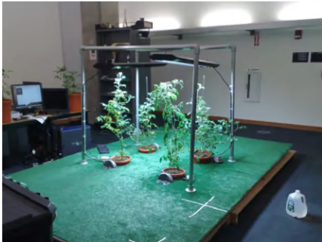
Fig. 1. Tomato plants are arranged on a platform of 3 × 4 meters. Plants are illuminated by growing lights.
grand challenge required designing and programming robots to interact effectively and autonomously with the real world. We describe the system architecture and algorithmic de-tails that constitute the distributed robot garden. We also describe experimental results for watering plants, identifying tomatoes, harvesting tomatoes, and coordinating the inter-action between robots and plants in this system that have been collected during a spiral-based design approach and motivated our design decisions. Our work provides a proof of concept working system but much work remains to be done to achieve our vision of self-sustaining precision agriculture with teams of gardening robots.
A. Project Structure
The system has been designed following a spiral-design philosophy that aimed at experimental evaluation of working sub-systems of the system after each term (Summer ’08, Fall ’08, Summer ’09) and a rotating student population. This approach has led to a series of major design revisions for almost all of the hardware components, sensors and algorithms and has led to the system presented in this paper. B. Related work
Commercial agriculture has reached a high level of au-tomation, although mainly for broad-land crops, e.g. using autonomous combiners. Similarly, fine-grain satellite im-agery is commercially available for targeted pesticide and fertilizer application. More recently, autonomous solutions have been developed for specialty crops such as apples [1], cherry [2], tomatoes [3], mushrooms [4], or cucumbers [5],
The 2009 IEEE/RSJ International Conference on Intelligent Robots and Systems
among others. Also, embedding sensors in the environment has been studied. For instance, in [6], [7] distributed wireless sensor networks for precision agriculture (e.g. irrigation) are presented. Our work aims to extend this body of research by focusing on precision agriculture tasks where autonomous mobile agents are networked with the environment. Other instances of systems that heavily rely on sensors and actu-ators embedded in the environment in a home companion context are [8], [9].
C. Outline
We start with describing the system architecture that consist of robots and plants networked with each other (Section II). We will then describe the individual components of the robotic system: Navigation and Path-Planning (Section III), Object Recognition (Section IV), Inventory (Section V), Visual Servoing and Grasping (Section VI), and Task Allocation (Section VII). We will then present experimental results for selected components of the system in Section VIII.
II. SYSTEMARCHITECTURE
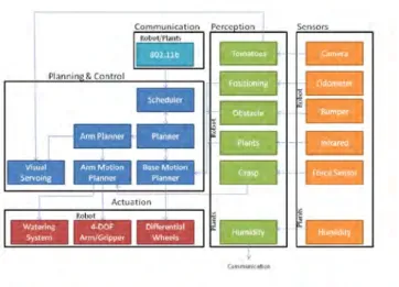
The distributed robot garden architecture (Figure 3) con-sists of robots and computationally enhanced plants (Figure 2) and includes the following subsystems :
a) Robots:
• Notebook computer running Ubuntu Linux.
• An iRobot Create providing a bumper sensor (left/right), four cliff sensors, a wall sensor and an infra-red sensor on the robot base. The robot has been retrofitted with a rear-end caster wheel to improve odometry, has been powered by an external battery and is outfitted with a laser-cut Delrin structure to attach its peripherals. The robot is controlled from the notebook using an USB-to-Serial connection.
• Servo board (Lynxmotion SSC-32), which controls the arm, provides an analog-digital converter for the force sensor, and PWM control for the water pump using an USB-to-Serial connection.
• Water tank and pump (Hargraves) connected to the SSC-32.
• 4-DOF arm (Crustcrawler robotics) with gripper and resistive force sensor (0-10 Newton) connected to the SSC-32 (Figure 2, right).
• Lithium-Polymer battery pack (19.2V, 130Wh) for pow-ering the entire system.
• Logitech Quickcam connected to the notebook using USB.
• Hagisonic Stargazer relying on 4 markers mounted at the ceiling for global localization.
• Atheros PCMCIA radio card.
The ability to program, debug, and visualize the system on the notebook (vs. an embedded PC) drastically sped up the software engineering process. Also, USB (together with a series of TTL serial port to USB converters) proved to be an elegant solution for connecting all of the robot’s components. The Crustcrawler arm does not allow for position-based
feedback control, but turned out to be sufficient for proof-of-concept visual servo based grasping at a fraction (around 1/20th) of the cost of the smallest available industrial arm that we could find at the time of writing. Using a single battery pack for powering all of the system’s component is motivated by the need for autonomously charging the system using a docking station. Battery power is fed directly to the notebook and regulated down using a series of switching regulators to accommodate the voltage requirements of the different platforms. The Logitech Quickcam has been se-lected for its low price trading off achievable frame rate (factor 3) with a Firewire camera.
b) Plants:
• Cherry tomato shrubs of approximately 1m height that continuously carry fruits in all stages of maturity (flow-ers, green and red tomatoes). Every shrub grows in a dedicated pot.
• iRobot docking station, which provides an infrared field that allows a robot to autonomously dock. The dock is retrofitted to provide charging current to the 130Wh battery pack.
• Humidity sensor (Vegetronix).
• Wireless sensor node running OpenWRT Linux (tem-peraturealert.com) on an Atheros AR2315 radio-on-a-chip.
• Each plant has a unique identity provided by its IP address in the mesh network.
Embedding the plants with sensing, computation and com-munication abilities turned out to have numerous advantages: performing humidity sensing on the plant guarantees to respond to detect plant needs in the most timely fashion (as opposed to a mobile robot measuring each plant using a probe). Storing the result of fruit inventory performed by a robot on the plant vs. a central server provides a distributed and hence scalable and robust solution and comes at very little computational cost. Finally, coordinating plant-specific tasks by the plant itself allows to forgo a centralized task allocation system, which again contributes to the scalability and robustness of the overall system.
In our experimental setup, four potted plants are aligned in a grid on a 3×4 meters elevated astro-turf field (Figure 1). Robots and plants communicate via an ad-hoc mesh network. The plants provide the following functionality:
• A plant periodically reads its humidity sensor and posts a watering request when the reading falls below a threshold.
• Upon request, a plant reports the location and maturity (red or green) of its fruits in a local coordinate frame. • A plant accepts the location and maturity status (red or
green) of a new fruit from a robot and stores it in its local database.
• Upon request, a plant deletes a fruit from its database. The robots have the following functionality
• Navigate to a specific plant and dock at its pot. • Water a plant.
• Provide an inventory of a plant (fruit maturity and
Fig. 2. Robots are equipped with an end-effector, camera, localization system and watering device that are controlled by a notebook computer. Plants are enhanced with a wireless embedded Linux device that can monitor its status using a humidity sensor and information collected by the robot as well as issue requests.
location in local coordinates) using its on-board camera, merging it with the current inventory obtained from the plant.
• Pick a specific fruit on the plant.
All of these functions are implemented as web services, leveraging standard tools, and rely on a TCP/IP connection to a specific robot or plant.
A. Robot Architecture
The software architecture for the robot is depicted in Figure 3. The core processes are the Scheduler and the Planner. The Scheduler’s job is to coordinate and maintain a queue of high level tasks that the robot needs to accomplish, such as “Water plant #2”, these tasks can be either generated by the plants or injected by a human supervisor. For this, the scheduler receives messages from the common gateway interface (CGI) of an Apache web server that accepts HTTP requests on the local mesh-network IP.
The Planner is in charge of getting a task from the scheduler, decomposing it into a series of jobs each of which can be handled by an individual module, and then overseeing the execution of those jobs. For this, the planner interfaces with the navigation and visual servoing process as every task in our system can be decomposed into a navigation and a manipulation step.
All software modules are locally communication using the inter-process communication (IPC) framework ROS (Robot Operating System) [10], which is available open source and provides bindings for a wide range of programming languages (Python, LISP, Octave, and C) and works by exchanging custom data packets using shared memory or using a local network. ROS differentiates itself from other packages with similar intent such as LCM (Lightweight Communication and Marshalling) [11] by providing a large number of open source algorithms, and visualization and
Fig. 3. Overall system architecture including robots and tasks.
management tools that can be readily integrated into ROS systems.
In their current implementations, both ROS and LCM are only of limited use for wireless inter-robot communication. We initially implemented the system using LCM as it does not require a centralized name server, which we consider preventive in a distributed system. It turns out, however, that the main bottleneck is that only little control is available where messages get routed (in fact LCM uses UDP flood-ing) and that UDP is unreliable as it is a connection-less protocol. We therefore implemented robot-robot and plant-robot communication primitives using web services, i.e. information is transmitted by requesting a specific document on the remote machine using the HTTP protocol. Using the common gateway interface (CGI) on a robot’s or plant’s web server, this approach allows for execution of arbitrary code on the target platform and to report its output via the HTTP protocol. Likewise, robots can interact with each plants using a lightweight web server on the plant (lighttpd) and the libcurltoolchain.
B. Plant Architecture
The plant’s functionality was implemented using the Linux crondaemon for periodically checking humidity status, the wget tool for issuing HTTP requests to the robot and the lighttpdweb server together with a PHP interpreter to serve and update information about location and maturity of fruits. This information was stored and transmitted in JSON format, which is similar in intent than a XML description but provides a more compact representation for simple table data. C. Network Architecture
The robots and plants establish an ad-hoc mesh network using the Optimized Link State Routing (OLSR) algorithm (which is available in binary form for both Ubuntu and OpenWRT). OLSR is a link-state routing algorithm. OLSR implements a series of optimizations geared toward large-scale wireless networks and has proved its performance in city-scale networks involving multiple thousand nodes. Each
node floods information about its links to its neighbors until every node has discovered the other nodes and links. Each node then runs the same local shortest path computation algorithm from itself to any other node. We implement broadcasting by issuing HTTP requests sequentially to all IP addresses that are shown in the kernel routing table. Since the routing table also maintains a hop count (roughly corresponding to the spatial distribution of the nodes), this approach can also be used to address only nodes that are within 1-hop communication.
III. NAVIGATION ANDPATH-PLANNING
Robots use the basic navigation structure provided by the Create platform to travel to specific plants. It turned out that solely relying on odometry for localization is not sufficient for navigating passages only few centimeters wider than the robot. In particular, using only odometry does not allow the robot for recovering from errors. For global localization, we selected the Hagisonic Stargazer that provides relatively accurate localization and orientation (±2cm) by detecting in-frared markers mounted at the ceiling. Each marker consists of at least four reflecting stickers that are arranged in a 4x4 matrix and encode a unique id. Knowing the position of each marker in a global coordinate frame then allows each robot to compute is position using a transformation and rotation.
The Hagisonic sensor provides position information at roughly 2 Hz whereas odometry send updates at 50Hz. Therefore, and because we expect odometry to outperform the global localization system on short distances, position information from both sensors is fused asynchronously. Whenever new sensor data arrives, the robot either inte-grates odometry with full confidence or updates the position estimate using the global positioning information using an exponential average filter with 10% weight for new incoming data. We choose this policy for filtering occasional jumps in position that correspond to noise from the Stargazer sensor, which happens rarely, however. This is particularly noteworthy as the bright lights emitted by the growing system emit considerable large amounts of light in the IR spectrum. Each robot is equipped with a configuration-space map of the environment that is provided by ROS mapserver component. The pots are arranged in a regular pattern, which let the system scale also for large numbers of pots. For path-planning, the navigable space of the map is discretized into a grid of 1cm2 cells and paths are planned using the Wavefront algorithm implemented by the ROS package with the same name. The Wavefront package also accepts updates to the local map by a laser range scanner, which is a standard message type in ROS. We are using this interface for injecting the position of other robots on the field into the map. For this, our localization node periodically (1 Hz) reads positions from other robots visible on the mesh via the HTTP protocol and emulates a laser range scanner mounted at the origin of the coordinate system.
To navigate to a plant, the robot plans a path to a point in front of the pot’s docking station and then docks at the plant using the Create’s built-in docking algorithm. The actual
location that is required for successful docking is known by the plant and transmitted to the robot at each service request. In case of a collision (usually due to poor localization), the robot launches a low-level avoidance behavior, which eventually leads to recover a safe position, from which the planner will re-plan.
The dock provides three infrared rays that encode three different bytes and can thus be distinguished by the robot and provide a sense whether the dock is to the left or to the right in the direction of driving. Although the Create can detect whether it is charging at the dock, we retrofitted the dock for providing the charging source for the 130Wh battery to the robot. We therefore rely on a combination of red buoy, green buoy and force field detection for establishing whether the robot is close enough to the dock.
IV. OBJECTRECOGNITION
The goal of object recognition is to identify the centroid of red and green tomatoes, associate the centroid with coordi-nates in the plant-fixed coordinate system, communicate this location to the plant and use it for visually servo to a fruit for grasping. The location is used by the plant to maintain the fruit inventory and to give harvesting robots guidance on where the tomatoes to be harvested are.
Recognizing plants and tomatoes is a significant challenge because the foliage has complex geometry and affects light-ing in unpredictable ways. The tomatoes are generally round, but their exact size and shape has many variations. The tomatoes may be partially obscured by other tomatoes or leaves. Their shiny skin gives spectral highlights due to the reflection of light.
For this project, we investigated two distinct approaches for object recognition: feature-based, resource intensive clas-sifiers as well as filter-based clasclas-sifiers that rely on a combi-nation of Hough circle transform (for detecting circles), the Sobel filter (for detecting smooth areas), and color filters for detecting red and green areas as well as spectral high-lights. The output of each detector was then weighted and combined to a single estimator.
Image processing routines were implemented in Matlab (for feature-based approaches) and SwisTrack [12], which provides a graphical user interface to OpenCV and allows for rapid prototyping of image processing algorithms. SwisTrack was then interfaced to ROS allowing the visual servoing component and the inventory component to receive fruit locations.
A. Feature-based Object Recognition
Object recognition is formulated as the convolution of an image with a target pattern. If the target pattern can be found, the convolution will yield high values in this region. An extension of this approach is to use many small discriminative features, i.e. small patches that are relevant to the target pattern [13], and store the relative location of each feature with respect to the object’s center. The set of features serves as a joint classifier that collectively votes for a specific location. In order to identify which features are most
Fig. 4. Left:Result of convolution of input image with 40 feature/location pairs. Red dots correspond to local maxima. Right column: Detected fruits are highlighted with a rectangle. Notice the false-positive and misses in the bottom row.
discriminative, [13] applies a machine learning technique known as boosting. In practice, this involves taking a set of pictures with known object locations and choosing random features of the images to vote on the center of the object by convolving the feature with the target image in an offline learning step. These features are tested on other images from the training set, which allows selecting those that are most promising to detect objects in a wide range of images. If a feature turns out to be useful for a number of images in the training set, its weight is increased. If not, its weight is decreased.
We generated a training set consisting of a large number of red and green tomatoes. We labeled the data using the online tool LabelMe1 [11]. The 40 most dominant features were than extracted using the boosting algorithm (available online2).
After the best features and weights pairs are extracted from the training set, a convolution of a feature and the target image highlights possible locations of the class described associate with this feature. Figure 4 shows two examples with green tomatoes. As tomatoes vary drastically in size depending on the distance to the camera, we convolved the features not only with the target image, but also with a number of down-scaled versions.
Processing time of this algorithm is approx. 10-30 seconds per image, and depends on the number of features and number of scale variances used (see [13] for details on the computational complexity of the algorithm). Since the main feature of tomatoes is its relative lack of features, the algorithm achieves only around 34% success rate in identifying tomatoes. We next compare this approach to a filter-based algorithm for recognizing tomatoes.
1http://labelme.csail.mit.edu
2http://people.csail.mit.edu/torralba/shortCourseRLOC/boosting/boosting.html
Algorithm 1: TOMATO DETECTOR(PSEUDOCODE)
Data: Image frame from color video
Result: Position and color of all detected tomatoes in the frame foreach frame do 1 smooth = Sobelframe 2 red = MinMaxColor(RedPlane(frame)) 3 green = MinMaxColor(GreenPlane(green)) 4
redTomatoes = MinMaxArea(red ∪ smooth)
5
greenTomatoes = MinMaxArea(green ∪ smooth)
6
ROSPublish (redTomatoes, greenTomatoes)
7
Fig. 5. Detection of red and green tomatoes using a filter-based approach in the tracking software SwisTrack.
B. Filter-based Object Recognition
The filter-based tomato detection algorithm is shown in Algorithm 1. This algorithm relies on shape, color, size, and spectral highlights (due to the shiny skin of the tomatoes.) The gains for each filter were hand-tuned using quantitative feedback from a series of test images. The Hough transform reliably detects the tomato’s outer contours, but leads to a large number of false-positives triggered by the foliage. Relying on spectral highlights (corresponding to white image patches on each fruit (but not on the leaves) is not robust with respect to changing lighting conditions. Smoothness (corresponding to dark regions after Sobel-filtering) is the most dominant feature for both red and green tomatoes. By combining this information with a constraint on the minimum and maximum area of each blob we were able to develop a tomato recognizer with high precision performance. Color is used to differentiate between red and green tomatoes.
Sample detection results for tomatoes of different colors are shown in Figure 5. The processing time of this algorithm was in the order of 1/3 second per image.
V. INVENTORY
The inventory task consists of a systematic scan of the plant to identify and store the location and color of each fruit on the plant’s router. If there is previous inventory, the new inventory data is used to compare and update the
Algorithm 2: INVENTORY(PSEUDOCODE)
Data: Sequence of end-effector positions for systematic scan Result: Position and color of all detected tomatoes on the
plant, distance threshold for merging tomatoes in previous inventories
foreach end-effector position do
1
moveToPosition(end-effector position)
2
tomatoes = ROSGetTomatoes()
3
if inventory available then
4 MergeInventory(inventory,tomatoes) 5 else 6 WriteInventory(tomatoes) 7
plant router. A tomato’s description consists of: 1) the robots relative position to the plant at the time of detection, 2) the tomato’s x and y image coordinates (in the scanning plane), 3) radius, 4) color, and 5) confidence level of the measurement. The confidence level is updated every time using the detection accuracy (75%, see below) such that confidence increases if a tomato’s description is consistent throughout several inventories, and decreases otherwise. The inventory algorithm is given in pseudo-code as Algorithm 2.
VI. VISUALSERVOING ANDGRASPING FOR
HARVESTING
Harvesting tomatoes requires several steps: identification, reach, grasping, and removal. We use the output of the object recognition and inventory module as input to a visual servo-ing algorithm for reachservo-ing, graspservo-ing, and removservo-ing the fruit. The visual servoing algorithm uses the color-based object recognition and approximate knowledge of the location of a tomato to drive the robot manipulator to grasp the tomato. As the locations of the fruits can only be approximately known from an inventory step using the feature-based classifier, we use a closed-loop control algorithm to align the gripper with the fruit and eventually execute the grasp. We implemented an image-based visual servoing algorithm [14]. The motion of a robot end-effector is calculated in Cartesian space using the perceived error in the camera image.
Using a feedback controller with proportional gain, we can now calculate the desired position of the end effector by the inverse of the interaction matrix. Calculating an estimate of the interaction matrix for a specific camera/end-effector configuration requires knowledge about the geometry of the camera relative to the end-effector, its focal length, and the ratio of pixel width and height, which we established using simple experiments that consisted of moving a target of known dimensions in front of the camera. Notice that the interaction matrix requires an assumption about the distance of the object. We solve this by assuming all the tomatoes to have a constant radius.
The visual servoing algorithm is summarized as Algo-rithm 3.
VII. TASKALLOCATION
The high-level coordination of all the activities required to maintain the tomato garden is done via a task allocation
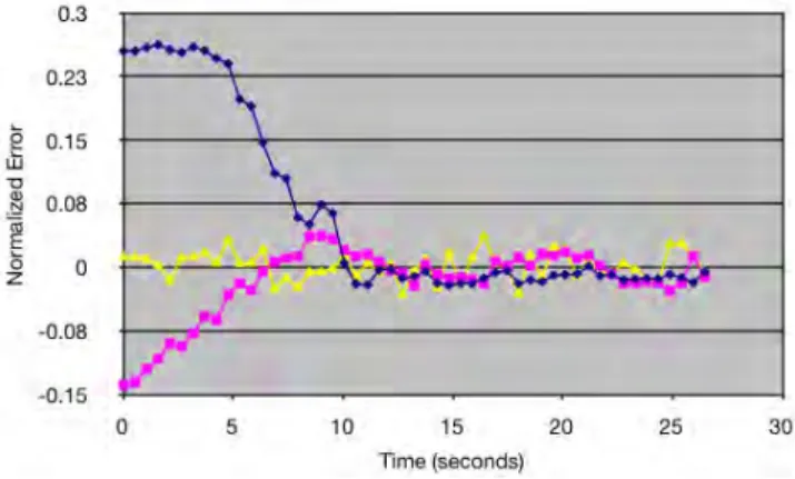
Fig. 6. Sample trajectory describing the Cartesian error of the robot’s end-effector from its initial position to a successful grasp.
Algorithm 3: HARVESTING(PSEUDOCODE)
Data: Sequence of image frames, inventory Result: Grasped fruit
selectTomato(inventory) 1 while !grasped do 2 tomato = ROSGetTomato() 3 error = goal-tomato 4 if error==0 then 5 graspTomato() 6 else 7 nextpos = ImageJacobian(error) 8 moveTo(nextpos) 9
algorithm. The task allocation algorithm keeps track of the active robot tasks and requests (e.g. watering, inventory, harvesting) and allocates each task to exactly one robot. The algorithm is decentralized and aims for load-balancing among robots. Each task has a unique ID. Tasks are generated either by a user requesting a tomato, or by a plant requesting to be visited (for watering, inventory, or harvesting). For each task, a request is broadcast to each robot over the mesh-network. Robots reply with their cost of task completion. The cost is a function of the distance to the plant, the length of the task queue and the abilities of the robot (infinite cost for infeasible tasks—e.g. a robot that does not have the watering system installed will not be able to complete the watering task).
Task assignments are periodically re-allocated to ensure success even in the presence of robot delays and failures (see also [15] for a similar scheme and its analysis).
VIII. RESULTS
The algorithms described have been implemented in C, C++, PHP and Python and are interconnected by ROS messages and web interfaces. We evaluated the reliability of each robot operation, the reliability of the plant sensory-computational system, the ability of the system to coordinate multiple robots, and the effectiveness of the task allocation algorithm with up to 2 robots. The accompanying video shows two robots coordinating for one harvesting and two watering task.
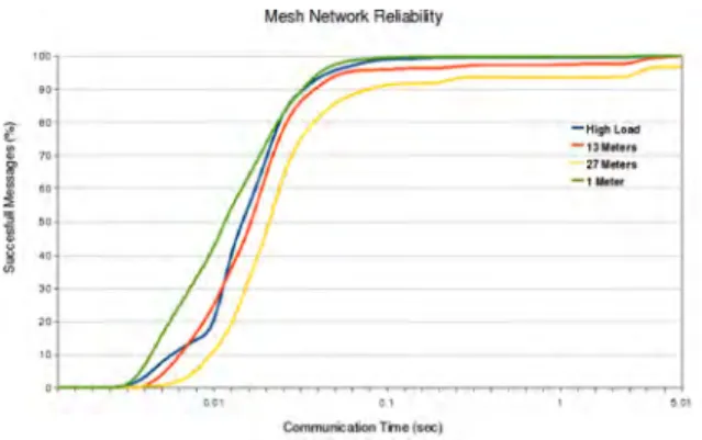
Fig. 7. Delay distribution for packet transmission over the ad-hoc network as a function of the distance and network load.
A. Networking
We evaluated the data rates in the network of robots and plants and quantified the effects distance and high network load had on the messages that were sent. In this experiment, a message was judged “successful” if it was sent and received properly. To see what effect distance had, we had one computer send messages to the routers at a distance of 1m, 13m, and 27m. To measure the success rate of messages sent under high load, we had 4 laptops next to each other, all sending messages, at a distance of 1m from the routers. Overall, our experiments suggest that as long as the robots are within the experimental platform, it is reasonably to expect almost all of our messages (> 95%) to be sent and received within 0.05 seconds even under high network load (Figure 7).
We also demonstrated a sequence of experiments in which the task allocation algorithm controls two robots in parallel. In this experiment, each robot was tasked asynchronously to go to a different plant. Once docked at the plant, the task of the robot (e.g. watering or harvesting) was done according to the results described below.
B. Navigation and Watering
In order to evaluate the navigation performance of our system, we required a robot to loop in a square of 85cm side length. The robot’s position was consistently off by around 10% over 10 iterations. Odometry performed worse than expected from the specifications of the iRobot Create base due to the additional weight of arm, notebook and watering system. Even though the astro-turf ground provides sufficient traction to the robot’s wheels, it provides significant friction to the front and rear casters, which particularly impacts the accuracy of turns. By adding the external localization system, the performance of the navigation algorithm incurred no accumulated errors over 20+ loops along the test square. In the absence of global positioning information, getting stuck between the plants or supporting poles eventually leads to a total loss of orientation, which has been remedied by the Stargazer sensor.
In rare cases, however, navigation error lead to an orien-tation in front of the plants in which the robot was attracted by a neighboring pot when docking. This is mitigated by
the planner which supervises that the robot stays within a rectangle of 1 by 1.5m around the dock and navigates to the original launching point otherwise.
We evaluated navigation for watering by starting a single robot in the top-left corner of the arena. We tasked the robot with watering two different plants, one closer to the origin, 6 and respectively 4 times and solely relying on odometry. Watering takes approximately 20s and involves moving the arm toward the soil using open-loop control. The average navigation time to reach the closer dock was 79.5s ± 11.3 and 94.25±8.9 for the dock farther away. We observed 100% success rate of watering over 100+ trials.
C. Object recognition and Inventory
We trained classifiers using the boosting algorithm [13] for red and green tomatoes using a training set of 17 images that were labeled using [11]. We then tested the classifiers on live images from the robot. Over 150 images, each containing at least one tomato, the classifiers detected and correctly classified around 34% of the tomatoes and 38% false-positives. We also counted the total number of tomatoes that were present in the images and calculated the percentage of tomatoes that the algorithm did not recognized at all to 44%. Of these 44% misses, 87% were expected as the tomatoes were occluded or cropped, for which we did not train appropriate classifiers.
As the detector convoluted 15 scaled instances of each image with the 40 most important features, processing one image requires approximately 16s per image on the Centrino Duo notebook.
Using the Sobel-filter based tracker in Algorithm 1, we improved the rate of correctly classified tomatoes to 75% for red and green tomatoes.
Inventory took an average of around 45s over 10 trials. D. Visual Servoing and Grasping
We conducted the following experiment ten times in a row using both the feature-based and filter-based detection approaches. The robot starts in a docked configuration with a plant. The robot is given the coordinates of a tomato and moved its arm from the docking configuration to a position close to the tomato (given its location stored on the plant). The robot then uses the visual servo feedback controller to grasp the tomato.
Using the feature-based approach, grasping was successful in 50% of the time over 10 trials. The average duration for the successful trials was 30.6s ± 16.1 and 30.8 ± 31.6 for the unsuccessful trials.
The filter-based approach improved the performance of the visual servo to 75% successful grasps over 20 trials. The average time was 28.3 ± 10s for the successful trials. The success rate of this algorithm is closely related to the object recognition performance. In case the robot started in a position that did not lead to any of the expected detections, the visual servo immediately terminates.
Reasons for failure were mostly due to singularities on the trajectory from initial position to desired grasping lo-cation and false-positives on object recognition that lead to
premature grasping. The force sensor helps detecting failed grasping attempts for false-positive detections. It does not help, however, when the gripper grasps another part of the plant, which we also observed.
IX. DISCUSSION
Networking. OLSR will scale for thousands of nodes. However it might make more sense (for this particular application) to forgo routing altogether and simply flood the requests into the network with a limited hop count. Although IEEE 802.11b allowed us to leverage off-the-shelf software and protocols, a less resource intensive, short range communication system such as infrared might be more appropriate. As a side-effect the infrared signals could also be leveraged for navigation.
Plants. The system performance can be enhanced by using a model of plant growth. This will allow plants to predict their status in between updates received from robots and it is part of our current work.
Navigation and Path Planning. If global positioning is available, the gardening system can recover from navigation errors as described in this paper. If global positioning is not available, robots with better odometry and navigation sensors are needed.
Object Recognition. Object recognition using joint boosting is resource intensive and is difficult in the gardening domain. A key problem is that texture-less tomatoes provide only very limited features by themselves. Thus, dominant features are mostly located at the boundary of tomato and background, which leads to poor performance when the background varies strongly as in our experiment (astroturf, leaves, other robots, laboratory).
Visual Servoing. Visual servoing fails when the robot is unable to detect the tomatoes at the expected position. This situation can be improved by implementing an additional planning step using position-based visual servoing, which systematically explores the region of interest from different angles, potentially also involving movement of the base.
Grasping. As the orientation of the stem growing out of the tomato fruit is not always vertical it turns out that we could only grasp a subset of tomatoes without an additional degree of freedom (wrist rotation) and appropriate image detection algorithms. Also, the limited workspace of the arm imposes constraints on reachable tomatoes.
X. CONCLUSION
This paper describes our experience with designing and building a distributed robot garden as part of a project class with two teams of undergraduate students. We have developed a network of mobile manipulators and plant sensor networks. We demonstrated that our system can coordinate plant requests and robot activities for precision plant wa-tering, fruit inventory, and fruit harvesting. However we struggled with the robustness of the operations provided by the hardware and the limited workspace of the chosen arm. Particular challenges were the inital lack of a global localization mechanism for recovering from navigation errors
and the limited robustness to changing lighting conditions of object recognition during visual servoing.
Our current focus and challenge in this project is achieving persistent autonomous operation of the distributed gardening robots for periods on the order of several weeks.
Acknowledgments
We would like to thank A. Torralba for his help on feature-based object recognition, J. French, J. Myers and A. Zolj who have been working on the Distributed Robotics Garden as part of the MIT Summer UROP program in 2008, Kevin Quigley and Marsette Vona for providing their visual servoing algorithms, and Michael Otte for helping out on navigation.
REFERENCES
[1] A. Tabb, D. Peterson, J. Park, S. by ASABE, and O. Portland, “Segmentation of apple fruit from video via background modeling,” American Society of Agricultural and Biological Engineers, vol. 63060, 2006.
[2] K. Tanigaki, T. Fujiura, A. Akase, and J. Imagawa, “Cherry-harvesting robot,” Computers and Electronics in Agriculture, vol. 63, no. 1, pp. 65 – 72, 2008, special issue on bio-robotics.
[3] N. Kondo, Y. Nishitsuji, P. Ling, and K. Ting, “Visual feedback guided robotic cherry tomato harvesting,” Transactions of the American Society of Agricultural Engineers (ASAE), vol. 39, no. 6, pp. 2331– 2338, 1996.
[4] J. Reed, S. Miles, J. Butler, M. Baldwin, and R. Noble, “Automatic mushroom harvester development,” Journal of Agricultural Engineer-ing Research, vol. 78, no. 1, pp. 15–23, 2001.
[5] E. van Henten, J. Hemming, B. van Tuijl, J. Kornet, J. Meuleman, J. Bontsema, and E. van Os, “An autonomous robot for harvesting cucumbers in greenhouses,” Autonomous Robots, vol. 13, no. 3, pp. 241–258, November 2002.
[6] W. Zhang, G. Kantor, and S. Singh, “Integrated wireless sen-sor/actuator networks in agricultural applications,” in Proc. of ACM SenSys, November 2004, p. 317.
[7] Y. Kim, R. Evans, W. Iversen, and F. Pierce, “Instrumentation and control for wireless sensor network for automated irrigation,” ASAE Paper No. 061105. St. Joseph, Michigan, 2006.
[8] A. S. ad M. Broxvall, M. Gritti, K. LeBlanc, R. Lundh, J. Rashid, B. Seo, and Y. Cho, “The peis-ecology project: Vision and results,” in Proc. of the IEEE/RSJ Int Conf on Intelligent Robots and Systems (IROS), Nice, France, 2008, pp. 2329–2335.
[9] R. Rusu, B. Gerkey, and M. Beetz, “Robots in the kitchen: Exploiting ubiquitous sensing and actuation,” Robotics and Autonomous Systems, special issue on Network Robot Systems, vol. 56, pp. 844–856, 2008. [10] M. Quigley, K. Conley, B. Gerkey, J. Faust, T. Foote, J. Leibs, R. Wheeler, and A. Ng, “Ros: an open-source robot operating system,” in International Conference on Robotics and Automation, Workshop on Open-Source Robotics, ser. Open-Source Software workshop, 2009. [11] B. Russell, A. Torralba, K. Murphy, and W. Freeman, “Labelme: A database and web-based tool for image annotation,” International Journal of Computer Vision, vol. 77, no. 1–3, May 2008.
[12] T. Lochmatter, P. Roduit, C. Cianci, N. Correll, J. Jacot, and A. Mar-tinoli, “Swistrack - a flexible open source tracking software for multi-agent systems,” in IEEE/RSJ International Conference on Intelligent Robots and Systems (IROS), Nice, France, 2008.
[13] A. Torralba, K. Murphy, and W. Freeman, “Sharing features: efficient boosting procedures for multiclass object detection,” in Proceedings of the IEEE Computer Society Conference on Computer Vision and Pattern Recognition (CVPR), 2004, pp. 762–769.
[14] F. Chaumette and S. Hutchinson, “Visual servo control part i: Basic approaches,” Robotics & Automation Magazine, vol. 13, no. 4, pp. 82–90, December 2006.
[15] P. Amstutz, N. Correll, and A. Martinoli, “Distributed boundary cover-age with a team of networked miniature robots using a robust market-based algorithm,” Annals of Mathematics and Artifcial Intelligence. Special Issue on Coverage, Exploration, and Search, 2009, to appear.