COLLABORATIVE DESIGN PROCESS
byWassim EI-Solh
Submitted to the Department of Civil and Environmental Engineering in Partial Fulfillment of the Requirements for the Degree of
Master of Engineering in Civil and Environmental Engineering
at the
MASSACHUSETTS INSTITUE OF TECHNOLOGY
May 2000
0
Wassim El-Solh, MM. All rights reserved.
The author hereby grants to MIT permission to reproduce and distribute publicly paper and electronic copies of this thesis and to grant others the right to do so.
Author
Department of Civil and nvjxliG'a Engineering May 17, 2000 Certified by
Feniosk Peh a-Mora Associate Profetsor in CEE )hesis Supervisor Accepted by
Daniele Vereziano Chairman, Departmental Committee on Graduate Studies
MASSACHUSETTS INSTITUTE OF TECHNOLOGY
COLLABORATIVE DESIGN PROCESS by
Wassim EI-Solh
Submitted to the Department of Civil Engineering on May 17, 2000,
in partial fulfillment of the requirements for the degrees of Master Of Engineering in Civil Engineering in Information Technology
Abstract
Software products are becoming increasingly complex as well as large. Software developers are also taking part of the globalization process whereby many teams spread around the world actually work together to build software. Difficulties due to language, culture, team culture and technology barriers thus add to the hurdle of achieving products both on time and on budget without sacrificing on quality. This thesis discusses the design process as experienced in the scope of a product jointly developed by the university of CICESE (Mexico), the Catholic University of
Chile (PUC) in addition to MIT. It encompasses modern practices and approach to develop software by a geographically distributed team, using modern technology for collaboration and software development.
Thesis Supervisor: Feniosky Pena-Mora Title: Associate Professor
Acknowledgments
I would like to thank Professor Feniosky Peia-Mora who initiated our interest in an exciting and promising subject. I am particularly grateful for his constant support and encouragement during the entire time duration of the DISEL project. Special thanks also to Prof. Jesus Favela and David Fuller, instructors respectively at CICESE and PUC, and especially to the entire ieCollab team without whom this project would have not been possible.
Finally, I would like to thank my parents for their great support and patience over the past five years.
Contents
1. The Disel Project _81.1. Objectives 9
1.2.The Team 10
1.3. Collaboration 13
1.4. CAIRO, ieCollab 15
2. Object Oriented Design
18
2.1.The Design Process 18
2.2. Object-Oriented Concepts 20
2.3.Object-oriented Implementation 26
2.4. Available tools for design: the Unified Modeling Language 29
3. Designing ieCollab 49 3.1. Features 49 3.2. CAIRO, ieCollab 51 3.3. System Architecture 53 3.4.Transaction Management 55 3.5. Meeting Management 61 3.6. Collaboration Server 62 3.7. Application Server 64 3.8. Client Interface 64
4. Distributed Design Challenges 68
4.1.The Location Barrier 69
4.2.The Language and Cultural Barriers 71
4.3.The Technology barrier 73
4.4. Effects of barriers 74
4.5. Recommendations 75
List of Figures
Figure 1.1: organizational chart of ieCollab during the fall semester 13
Figure 2.1: The Car Class 31
Figure 2.2: Class Inheritance 32
Figure 2.3: Example of Interface 33
Figure 2.4: Example of Association with Rolenames, Multiplicity [OMG, 99] __ 34
Figure 2.5: An Example of
Qualified
Association [OMG, 99] 35Figure 2.6: The XOR Constraint [OMG, 99] 37
Figure 2.7: Use Case, Using the Car Example 38
Figure 2.8: Sequence Diagram [OMG, 99] 40
Figure 2.9: Sequence Diagram with Focus Control [OMG, 99] 41 Figure 2.10: Collaboration Digram, at Instance Level [OMG, 99] 43 Figure 2.11: Collaboration Diagram at Specification Level [OMG, 99] 44 Figure 2.12: State Diagram for a Single Telephone Object [OMG, 99] 45
Figure 2.13: Concurrent Substates (top), Concurrent Transitions (bottom) [OMG,
99] 46
Figure 2.14: Activity Diagram [OMG, 99] 47 Figure 3.1: System Architecture of ieCollab (partial) 54 Figure 3.2: Main Use Case Diagram 56
Figure 3.3: Account Administration Sequence Diagram 57
Figure 3.4: Registration Sequence Diagram 58
Figure 3.5: Login Sequence Diagram 59
Figure 3.6: Logout Sequence Diagram 59
Figure 3.7: Database Diagram 60
Figure 3.8: WG and Meeting class diagrams 63
Figure 3.9: ieCollab class diagram 65
Figure 3.10: Main ieCollab GUI 66
List of Tables
CHAPTER 1
THE
DISEL
PROJECT
The Distributed Software Engineering Lab (DISEL), a project initiated in the M.Eng. Program at the department of Civil & Environmental Engineering at MIT, tries to reproduce the working environment of a software development team while introducing several modern technologies. Its main objectives are to define new ways of software development and management and provide to the participating students the skills needed for the present trends as well as the constraints found in the software industry. The students involved in the project accounted to 34 persons, from three different universities namely the Centro de Investigaci6n Cienifica y de Educaci6n Superior de Ensenada (CICESE, Mexico), Ponticifia Universidad Catolica de Chile (PUC, Chile) and Massachusetts Institute of Technology. The timeframe of the project was one academic year (9 months) even though students could freely leave the project at any point in time.
This thesis outlines the lessons learned during this year, with a focus on the practical implementation of the design process, in a distributed environment. The
DISEL project is first introduced, providing a description of the background in
which the project has taken place. The design process is then discussed, emphasizing the Object-Oriented approach and methods in order to introduce the reader to the technical standards and notations used afterwards. The Unified Modeling Language (UML) standard is detailed in this section. The actual design of the developed product (ieCollab) is specified next, as an example of the design process in a distributed environment. Finally, the last section discuss the experience, the limitations faced in designing ieCollab as well as the possible
recommendations to enhance the collaborative design process.
1.1 Objectives
The purpose of the DISEL project was threefold. First and foremost, it was to introduce students to modern development practices: the project reproduced the organization found in modern companies and distributed tasks and responsibilities among the team members. As companies are becoming increasingly global, so does the work and distribution of work across the company. It was thus essential to educate the students to work in a geographically distributed team so as to overcome cultural and technological
barriers. Finally, it was essential to introduce the students to rapid development techniques. Indeed, with the internet age, companies are increasingly trying to find new ways of reducing the time necessary for completing projects while maintaining high quality standards.
1.2 The Team
In order to conform to the structure usually found in modern companies, each person has been assigned one main function that will be described below. A minor role was also assigned so as to expose each person to the duties and responsibilities of a second role. Because the project was conducted in the scope of an academic class, students could choose to depart freely even when their duties where not fulfilled. This, in fact, reproduced the actual phenomenon that occurs in an actual company, which often has to adjust to human resource changes. However, the lack of the replacement ability produced a set of different constraints in the system that is not regularly found in the industry.
During the first part of the year, the team was composed of a total of 34 persons: 6 from CICESE, 5 from PUC and the remaining 23 from MIT. During the second period of the project, 11 persons have left, leaving 2 students from
The respective roles assigned were as follows:
Project Manager Team: Provides overall leadership to establishes the schedule to be followed in order to properly
PM team is to make sure group integrity is maintained along project.
the project and accomplish it. The the lifetime of the
Analyst Team: Determines the objectives/functionalities that the software is to address according to the client's needs. The analyst team executes the first step of producing the product by determining the technologies to be used as well as the overall framework of the system.
Designer Team: Often said to transform the requirements into the software blueprint whereby the overall system architecture as well as the implementation details are specified.
Validation Team: Verifies that the design documents are consistent/error free and actually addresses the specifications found in the requirements documents.
Programmer Team: Translates the design into a programming language that can be executed on a machine.
Tester Team: Evaluates the product and tries to point out defects in an ideal of reaching an error-free product.
Quality Assurance Team: Establishes the software engineering practices and monitors adherence to those practices throughout the software development life cycle.
Configuration Management Team: As change during a project is inevitable, the CM team tries to maintain the integrity of product and to make its evolution more manageable.
Knowledge Management Team: Sometimes denoted as the memory of the project, the KM team is responsible of storing finalized documents. It maintains a list of frozen as well as on-going documents as a reference to other members of the project.
BUSINESS MANAGERS MARKETING CONFIGURATION TESTERS
Jaime -PUG MANAGERS TAEReS I Chang -MIT
Justin - MIT Steven - MIT M esKenward -MIT
Eswar -MIT Pubudu -MIT Manuel -CIGESE Cesar -CICESE
Anup - MIT
REQUIREMENTS ANALYSTS DESIGNERS
KNOWLEDGE Polo -CICESE Hao - MIT
MANAGERS Rosa -PUs Wassim -MIT PROGRAMMERS
Paul - MIT Bharath - MIT Rafael - PUC Gyanesh - MIT
Hermawan - MIT Li-Wei - MIT Roberto - Cicese Sugata - MIT
MAria - PUC Alberto - PUC Alan -MIT__________________________
QUALITY ASSURANCE Nhi -MIT Kaissar - MIT Blanca -CICESE
Sae Yoon -MIT
Figure 1.1: organizational chart of ieCollab during the fall semester
1.3 Collaboration
In order to educate to universal collaboration, most teams have been split up geographically; differences in the language, in the culture as well as methods of work indeed have been felt and were expected to be overcome so as to deliver a product on time. While a common language - English - has been used, other differences were not expected to be reduced, on the opposite: each person was to learn how to operate and be flexible enough so as to respect other persons' values and methodologies. While several communication tools aimed at facilitating communication among persons and teams were used, Technology
proved to be the most challenging barrier to collaboration. Mirabilis' ICQ [www.mirabilis.com], Microsoft's NetMeeting [www.microsoft.com] as well as CAIRO [DISEL, 1998] were mostly used but failed to provide a convenient way for exchanging ideas in the scope of this work. It has been found that even when sound and video was at hand, enabled by a high-speed internet connection, social interaction was difficult thus creating a rift among persons trying to join forces. Indeed, the interaction generally present when members of a team are physically together lacked the human interaction factor including casual contact and personal expression. Because the members of different teams didn't know each other before the actual start of the work, this lack of social interaction first emerged as a frustration and then resulted in a disinterest in maintaining cooperation. As motivation weakened, so did the overall efficiency of the group, which was one of the main reasons of the project delay.
Netmeeting and ICQ, while enabling a full conversation are not adapted at a time when a close relationship is needed. Moreover, these tools are effective in only small teams of 2 to 3 persons but are not suitable for larger meetings.
A common repository was created and maintained during the full period of the
project so as to provide all members a common place whereby documents as well as comments and inquisitions were posted. The repository was directly accessed using a web browser and was thus accessible from any computer linked
to the web. This common space was organized according to the hierarchical paradigm used in the project. Each team posted its documents, considered comments from other teams and finalized their documents once corrections and adjustments were found to be satisfactory by all members. Periodic presentations closely accompanied the publication of each document were held so as clarify any misinterpretation and respond to comments.
Finally, the Concurrent Versions System (CVS) was used as the source code management of this project. Similarly to the repository, access to CVS was made available to any computer connected to the internet and set up with WinCVS (Windows platform) or cvs (UNIX).
1.4 CAIRO,
ieCollab
The product to be developed by our team was to provide a virtual meeting place, specifically targeted to the work environment - a software that addresses the exact working challenges faced by our team. The Collaborative Agent Interaction control and synchROnization (CAIRO) was developed during the last five years. It provides a virtual meeting environment where not only chat can be used, but also a drawing board and an agenda, concurrently accessible to all authorized users. One important feature of CAIRO is to represent the frame of mind of each
participant in order to attract the attention or otherwise show satisfaction /
dissatisfaction and other natural human behaviors. Eight different expressions were developed that can be used during any session of CAIRO. The important business advantage of CAIRO was to provide platform-independent software by using the Java technology thus making it accessible to the growing number of non-Windows users. Nevertheless, in order to use this product, users are to download the package from the web site and perform a relatively long installation. Moreover, the client user has to explicitly specify the computer to which he or she will be connecting to (i.e. the ip address), an operation that de-facto reduced the potential market of this software. ieCollab, on the other hand, was to address these issues while maintaining the competitive advantages of CAIRO. A three-tier approach was adopted: the client (or dumb terminal), the server and the database. Ideally, the client is a Java applet that is automatically downloaded by the web server on the user's machine. Therefore, the product is directly operational without requiring any installation or configuration from the user. In addition, the web server automatically connects the applet to an appropriate server without any external intervention.
Following is a brief description of the features of ieCollab, as specified by the Business team (from the ieCollab Business Plan, Nov. 1999).
"ieCollab is an Internet-based collaborative application service provider for communicating information and sharing software applications in a protocol-rich Java meeting environment. [ ...] ieCollab will develop virtual team management and execution collaborative applications to be deployed via the Internet, to allow easy access from all collaborators. Not only will participants communicate via a structured environment following formats such as Round Robin, Chairperson, Brainstorming, Lecture, they will also have access to commonly used tools specific to their industry. This unique blend of traditional communication tools such as audio, video and text-chat, industry-specific applications and meeting
protocols results in smoother meetings that finish on time and accomplish their goal".
Because of an Application Service Provider (ASP) based architecture, not only end users will be able to connect to ieCollab, but other ASP providers and portals will be able to access our services as well. Charging will be effected on a transaction-based fee.
However, due to time restrictions and project delays, the product delivered is only a stripped down version. It provides, nonetheless, the structure on which the entire application will be built.
CHAPTER 2
OBJECT ORIENTED DESIGN
This section presents the software design process, using an Object-Oriented approach. This is to provide the reader with an overview of the fundamental concepts used during the design of ieCollab. The UML standard is introduced, with an emphasis on the notation used.
2.1 The Design Process
The design process is the first step in the implementation of the software, followed by the actual implementation or "coding" and testing. It is also the first, but crucial, step to fostering quality as it defines the foundation as well as the approach adopted in the remaining of the software development.
In an earlier stage, the requirements analyst has gathered (and helped define) the customer's needs, resulting in specifying the scope of the software. The
In an earlier stage, the requirements analyst has gathered (and helped define) the customer's needs, resulting in specifying the scope of the software. The software's functionality, performance, interface (both with humans and other system elements) and other constraints are spelled out, as meticulously as possible in order to avoid any confusion both with the customer and with the designer. Ideally, the requirements analysis's end goal is to describe the information domain (information content and information flow), functions and behavior that the software should have [Pressman, 97]. The structure of the software is partitioned into logical modules, which are refined afterwards. In the conventional approach to software engineering, the designer maps information, functions and behavioral domains into data, architectural, interface and procedural designs, developed hereafter:
data design: developed after the information domain whereby the data structures and relationships are explicitly specified
architectural design establishes the relationships among the different structural components of the software
interface design:specifies the boundaries of the different modules - or the specification of the method of communication to one module or entity. An interface could be defined for human-to-software interaction or inter-module communication and is built from the data flow specified in the information domain
procedural design: specifies the implementation at the algorithmic detail.
Procedural design occurs after the data, architecural and interface design have been specified.
An object-oriented approach has been adopted in the case of ieCollab; the following sections describe, in more details, a modified but more appropriate methodology for the development of our product.
2.2 Object-Oriented Concepts
The Object-Oriented approach differs considerably from the conventional, structural approach, in a basic but fundamental point of view: the latter has a distinct "input-process-output" course while the former aggregates data and the processes that modify it. In the object-oriented approach, a set of different objects interact with each other to produce the output in opposition to the linear course of action found in the structural approach. As objects tend to be a representation of the ones found in every day's life, they are easier to develop and their behavior is known. Moreover, this modularization according to objects represents a natural approach of partitioning and categorization which simplifies the entire product development.
Modularity enables reuse and thus faster development: those components previously developed can directly be integrated into the new product since their functionality is known. Moreover, these older parts have been previously tested and survived integration; they can be relied upon and thus represent a valuable manner to reduce workload for the developing team and consequently cost. In addition, it has been found that object-oriented software was easier to maintain, to adapt and scale because of the inherent structural decoupling.
Even though many differences exist among different object-oriented programming languages, all pertain to four fundamental concepts: abstraction, encapsulation, modularity and hierarchy.
Abstraction
Abstraction is the act of generalizing or hiding unnecessary details. It allows considering a group of objects as one, emphasizing on the similarities of the group rather than the details of each object for the time being. This concept of simplification allows dealing with complex problems as it groups a multiple number of objects into a few broad categories easier to deal with at first hand. In the concern of enforcing safety on the road, for instance, the Registry of Motor Vehicles (RMV) may be interested in an application that could be used by police patrols. Motored-vehicles would be a possible categorization of all cars, vans, motorcycles and trucks. All of these objects have an engine power, an owner, a
maximum speed limit, a number of seats and so on. On the other hand, these motored vehicles are driven on the road, which encompasses highways, freeways and bridges. In applying abstraction, the analyst only regards features that are relevant to the problem: a transportation company would be interested in the volume of goods a vehicle can carry while individual users would attach more importance to the appearance. Finally, the level of abstraction is a representation of the level of specification: a car can be further subdivided into sports car, compact cars, 4-wheel drive cars and deluxe cars.
The abstraction is a method of defining the external view of an object while hiding all of the implementation details. The abstraction wall clearly defines this separation: the outer or public interface from the internal workings.
Encapsulation
While abstraction focuses on the outer specification, encapsulation is the concept
by which an object has a private part that is inaccessible to the outer world. All
interaction to the object is made through its interface while the processing of the messages are effected privately. The notion of the interface-encapsulation is essential in the context of software maintainability and reusability: a "good" software component is one that is general enough to serve several software products while achieving all functionalities that may be encountered for the given context.
Modularity
Dividing the software into a number of components helps analysts and designers cope with the complexity of the problem. As expected, it is indeed far easier to manage small pieces which functionality is well defined than dealing with a monolithic block of code. Moreover, as the project size increases, so does the internal interaction among the different parts of the software. Modularization provides a way of standardizing access to the different components by canalizing all messages into the interface.
The concept of clearly specifying the modules, their roles and their interface is crucial especially in a project whereby its members are geographically distributed. Each team, indeed, can rely on the interface of the modules implemented by other teams and develop its own modules appropriately.
Nevertheless, their specification is non-trivial as many considerations need to be taken into account: the appropriate level of modularization (too many modules offset the benefits because of the increased cost of integration), the scope of each module and finally the specification of the interfaces - all of which are accomplished at an early stage, while many details still haven't been specified.
The specification of the modularity is a fundamental step during the analysis and design process: it defines the architecture as well as the overall approach to the development of the software. The designer should thus give particular attention to this stage.
According to Bertrand Meyer [Meyer, 98], five criteria help assess the modularity:
" decomposability: the ability to decompose a problem into smaller
problems, easier to solve
" composability: the level of reusability of the module, as discussed before
" understandability: the level of self-description of the module, without the
necessity of gathering information from other modules
* continuity: the level of impact a small change would induce; ideally, a small change in one module should not require the modification but of a very few number of other modules
* protection: the level of containment of the propagation of errors
Meyer concludes that there are five principles which will help the designer achieve modularity in the scope of an object-oriented design:
" linguistic modular units: the design (and thus the specific modularity)
should be directly be translatable to the chosen programming language
" few interfaces
* explicit interfaces: the interaction between two modules should be direct and explicit for an outside viewer (i.e. no global data area)
The last three principles help achieve low-coupling, a measure of the interconnection among the different modules. Low-coupling results in easier maintainability and limits the propagation of an error
* information hiding: all information about a module hidden from the outside access
Hierarchy
One important aspect of object-oriented languages is not only to represent objects but also to implement the hierarchy among them. This ability of establishing relations among the objects further simplifies the understanding of a problem and, therefore, the modeling of a solution. While different designers would most probably develop different hierarchies even for the same situation, they would all try to represent one logical aspect of it, preferably as close as possible to the real hierarchy in the real situation.
Object-oriented languages provide two types of hierarchies: hierarchy by inheritance and hierarchy by aggregation.
Inheritance provides the ability to represent objects in a tree-like structure, whereby each object would carry on the characteristics of the parent objects in
addition of its specific details. Sometimes called an "is a" relationship between one object and the other, this method reduces redundancy as both the behavior and data can be inherited instead of being redefined, whenever needed. In the example pertaining to motored-vehicles, all sports car, compact car, 4-wheel drive car and deluxe car would inherit from a car object, defined as being a vehicle with an engine, 4 wheels etc.
On the other hand, aggregation is only a collection of different objects resulting in a new, more complex one. A car is comprised of a frame, an engine, 4 wheels, seats, etc. The relationship among the objects is said to be "has a".
Pressman [Pressman, 97] suggests favoring aggregation over inheritance whenever possible. Small hierarchies combined with aggregation, indeed, are more manageable and scalable while larger structures tend to be less flexible.
2.3 Object-oriented Implementation
In order to implement the previously defined concepts, three new functionalities have been introduced in most object-oriented languages. Classes, inheritance and polymorphism are explained hereafter.
Classes
Most often, a program makes use of a collection of objects that share similar behavior and state structure. These are said to belong to a same class, or are instances of that class.
A class is the part of the code which defines how an object is constructed, i.e.
what its constituencies and behaviors are. While all objects of a class have exactly the same methods, each one of them owns its specific copy of data, which can be altered according to the events that occur on that object. For instance, two identical cars will have the same physical characteristics and performance but will actually be in different geographic locations, have a different mileage and have a set of other different conditions.
During the execution of a program, both the class and its objects will actually be functioning. Nonetheless, only the objects will be interacting with other parts of the program while the class will have the task of creating new objects whenever needed.
Inheritance
Often, many objects of different classes will share similar characteristics. Inheritance enables classes to inherit all methods and attributes of other classes, instead of redefining them; the ancestor class is called a superclass while the
lower level class is said to be a subclass. A series of inheritance will thus establish a tree-like hierarchy characterized by an increasing level of details in the lower level classes. Moreover, by using inheritance, it is possible to refer to any subclass by using a reference of the superclass. This powerful concept enables
polymorphism, discussed hereafter.
Polymorphism
By the use of inheritance, a variable that refers to an object of a class can also refer to any object that is an instance of a subclass. This powerful feature enables the programmer to manipulate a set of different objects belonging to a same inheritance in an identical manner, whenever needed. In the example pertaining to cars, a listing request to a car variable would be enough to obtain the information of the car object whether the variable actually refers to a sports car or a deluxe car. In fact, the executable itself determines the type of object refered to and calls the corresponding method from the appropriate class. The binding is carried out at run time and is said to be a late binding.
2.4 Available tools for design: the Unified Modeling
Language
According to the dictionary.com website [URL: www.dictionary.com, April 20], the Unified Modeling Language (UML) is "a third generation modeling language, an open method used to specify, visualise, construct and document the artifacts of an object-oriented software-intensive system under development. The UML represents a compilation of 'best engineering practices' which have proven successful in modelling large, complex systems." The UML is the result of the combination of previous methods, respectively the Booch (by Grady Booch, 1991), the Object Modeling Technique (OMT, by James Rumbaugh, 1991) and the Object Oriented Software Engineering methods (by Ivar Jacobson, 1986). Since its creation, the UML has been de-facto a standard and has since been increasingly used in the analysis and design of large, object-oriented software products.
Following is a brief description of the notations used in the UML, which has been used in the designing of ieCollab. It does not cover the entire features, however, and the reader is encouraged to refer to the full specificatios for further details
Seven different diagrams are used to describe the workings of a system, including the descriptions of its components and the flow of information among them.
Class Diagram
The class diagram is a static, graphical representation of a model showing, in particular, the composition of this model, its internal structure and its relationships to other models or things. As noted in the UML notation, a class diagram can also contain interfaces, packages, relationships and also instances (objects) and would better be referred to as "static structural diagram" eventhough "class diagram" is widely established.
Classes
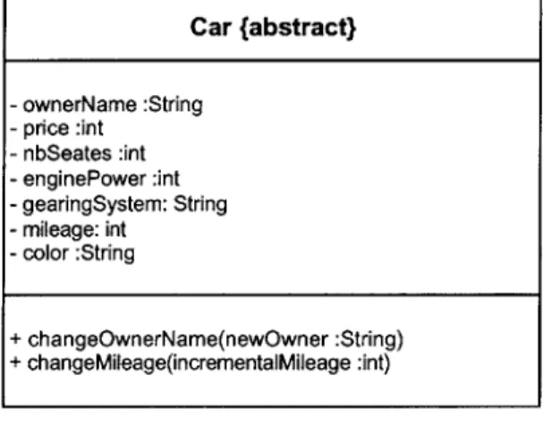
The basic component of the class diagram is the class, which represents one concept of the system being modelled. Drawn as a rectangle with three compartments, it describes the data structure, behavior and relationships to other elements. The first provides the name of the class while the second defines the attributes and the last lists the methods. A +, - or # sign represents the visibility of the attribute or method; the + sign is used in case of public visibility, the # sign for protected and the - sign for private visibility. Note that, by default, a class that is shown within a package is assumed to belong to the package;
otherwise, the full reference is specified using the syntax
Package-name::Class-name.
Following is an example of a class; note that, however, other representations of the class providing different levels of details exist - namely details suppressed and analysis-level details - but only the implementation-level details has been used in our design.
Figure 2.1: The Car Class
Object diagram
Eventhough the class diagram only provides a static view of the system, snapshots of objects can be represented, detailing the state of the objects at that instant. A class diagram with only objects and no classes is called an "object diagram". Car (abstract) - ownerName :String - price :int - nbSeates :int - enginePower :int - gearingSystem: String - mileage: int - color :String + changeOwnerName(newOwner :String) + changeMileage(incrementaMileage :int)
Inheritance
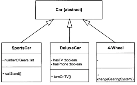
Also called generalization or specialization, inhertiance is "the taxonomic relationship between a more general element (the parent) and a more specific element (the child) that is fully consistent with the first element and that adds additional information." [OMG, 99] It is represented by a solid line between the superclass (or parent) and the subclass (the child) , with a hollow triangle placed towards the parent class.
Car {abstract}
SportsCar DeluxeCar
- numberOfGears :int - hasTV :boolean - hasPhone :boolean + callStand() + turnOnTV() 4-Wheel + changeGearingSystem()
Figure 2.2: Class Inheritance
Interfaces
UML also provides a specific representation of the interface. An interface is a specifier for the externally-visible operations of a class without the details of its implementation. While the representation of a class comprises all attributes and
operations of the described class, an interface only specifies the methods of that class that are externally visible, i.e. externally accessible. The use of interfaces reduces all the specifications of the class to a simple list of operations, the only information needed by external classes. It is also practical when the implementation details have not been completed yet.
Similarly to a class, the interface is noted by a rectangle symbol with the stereotype <interface and the list of the operations in the compartment below. A dashed line with a hollow triangular head is used to specify the supporting class, while a dashed line with an opened arrow shows the external classes that make use of the interface. Another notation also exists, with the interface represented by a circle linked by a solid line to the supporting class and a dashed line with an arrowhead to the class using the interface.
User
A se
Figure 2.3: Example of Interface Car {abstract} + changeOwnerName(newOwner :String) + changeMileage(incrementalMileage :int) interface Car + changeOwnerName(newOwner :String) + changeMileage(incrementalMileage :int)
Associations
Temporal structural relationships can be established among objects of different classes by using associations. Drawn as a solid line beween the classes it relates, the association specifies how each class is viewed by the other(s) by indicating a name for the entire association or a rolename at each end of the association. It is possible to establish an association from a classifer to itself but the ends should be clearly separated. Association instances are called links.
Binary associations are those that connect exactly two classes or objects and are
the most recurrent while N-ary associations link three or more classifiers. Contrary to binary association, the n-ary association is represented by a diamond linked to the classifiers involved in it.
The multiplicity is indicated at each end, next to the role. It can be a fixed value or indicate a range of values.
LJob 1 il
Companyemployer employee Pro
salary
worker[ 1
4
Manages
Figure 2.4: Example of Association with Rolenames, Multiplicity [OMG, 99]
. I
An association is an associaton class whenever it comports attributes or operations. These are specified in a class box linked by dashed lines to the classifiers.
A qualified asso ciation is one association that specifies a unique object across
the association. An association attribute value, the qualifier, which is unique within the set of links of the corresponding association, is used to determine the object being refered to. The qualifier, together with the association are refered to the composite key and are drawn as a box attached to the class box for the qualifier from which the typical association line is drawn. The qualifier is considered to be part of the association but not of the class.
Bank Chessboard account # rank:Rank file:File o.1 1i Person 1 Square
Figure 2.6: An Example of Qualified Association [OMG, 99]
Navigability is the explicit specification of the implementation of the association.
It is either one-way or two-way, and is represented by a small square next to the target class, i.e. next to the class that is being referenced. A hollow square represents a reference implementation while a solid square represents a by-value implementation.
Composition is a form of aggregation "with strong ownership and coincident
lifetime of part with the whole." [OMG, 99] The multiplicity of the aggregate cannot exceed one while that of the parts don't have any restriction. Composition is represented by a line and a diamond next to the aggregate for each one part.
Constraints
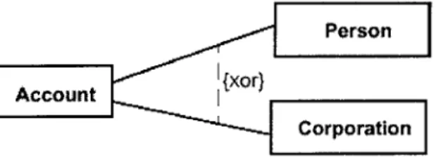
A constraint is a condition to be maintained on the corresponding classes or
associations. It is generally specified as a text comment enclosed within braces and placed next to the affected element. In case two symbols are affected, it is shown as a dashed arrow from one element to the other, representing the direction of the modification caused by the constraint. For three or more symbols, the comment is placed in a note symbol, linked to each one of the symbols by a dashed line.
Figu e 2 XPerson7 T e
Account{xr
Corporation
Use Case Diagram
A use case diagram is a representation of the interactions that may exist among actors and use cases. An actor can be any object - not necessarily a software component - that is involved in a transaction with the system being developed. On the other hand, the use case is the description of a specific functionality provided by a system, a subsystem or a class. The aim of the use case diagram is to describe the system's behavior under different circumstances and with the external factors through a collection of use cases.
The stereotype generally used to represent an actor is a "stick man" while use cases are shown as ellipses, along with their names. Among the use cases and actors are the use case relationships, as described hereafter:
Association:represents the participation between an actor and a use case; the association is shown as a solid line between the two.
Extend: a relationship between two use cases indicating that the instances of the use case being extended can be augmented by the behavior specified by the second use case. The extend relationship is represented by a dashed arrow pointed towards the base case with the stereotype <extend and an optional condition of the relationship.
Genera I ization:represents the generalization or the specialization relationship between two use cases. The relationship is represented by a solid line, with a closed hollow arrow pointing at the parent use case.
Include: the behaviors of a use case can be included in another use case
through this relationship. The representation is similar to the extend relationship but with the <include stereotype instead of <extend .
Buy Car
User
Refuel
Sell Car
Figure 2.7: Use Case, Using the Car Example
Interaction Diagrams
Interaction diagrams show "the patterns of interaction among instances" [OMG,
99]. They describe the behavior of the system by describing that of each
component (or instance). Interaction diagrams are case scenarios specifying which component is involved, in which situation and triggering what type of
response. Two different types of interaction digrams exist: the sequence and the collaboration diagrams. While both diagrams make use of the same underlying information, each form emphasizes a particular aspect of the interaction.
Sequence Diagrams
Sequence diagrams are generally used in complex situations. They also better describe real-time interactions among instances than collaboration diagrams but do not show the associations among them. The instances involved are shown along their "lifelines" and the sequence of the stimuli they exchange is specified. Even though several different forms of sequence diagrams exist, they all represent the fundamental information in the same manner.
In general, the different instances are horizontally aligned and thus their lifelines drawn vertically. Time proceeds along the vertical axis and downwards while, on the other hand, the arrangement of the objects on the horizontal axis does not bear any particular significance. The description of specific timing constraints, that of actions as well as other conditions are either noted in the margin or
labeled next to the respective stimuli.
In the following example, the different object are drawn as boxes and their lifelines as rectangles. The different messages among the objetcs are drawn as arrows labeled with a specific action.
(b~receiveime - a-sendTime < 1 sec.) {creceiveime - b.sendTime < 10 sec.) The call is muted through the network. (dreceiveTime - dsendTime < 5 sec.) At this point the paries can talk. a: lift receiver b: dial tone c:dial digit d: route ringing tone stop tone phone rings answer phone stop ringing stop> 4
Figure 2.8: Sequence Diagram [OMG, 99]
The following example represents another type of sequence diagram showing the focus of control respectively according to the lifetime of the instances.
jxchange
F~i~C4
Figure 2.9: Sequence Diagram with Focus Control [OMG, 99]
Collaboration Diagrams
A collaboration diagram is an interaction that is based on the roles found in the interaction. Unlike sequence diagrams, collaboration diagrams represent the associations that exist among objects but do not have a separate time dimension. Sequence numbers are used in order to track the sequence of actions taking place.
The collaboration diagram is either given at specification level whereby the ClassifierRoles, AssociationRoles and Messages (i.e. the roles and their structures) are shown, or at instance level where Objects, Links and Stimuli (instances corresponding to the roles) are displayed.
A collaboration diagram describes a Collaboration and often an Interaction. The former defines a set of roles (played by Objects) and their relationships, while the latter describes a set of Messages specifying the interaction between objects in the aim of achieving a certain result.
Boxes are typically used to represent Objects (or ClassifierRoles in the case the diagram is at specification level) linked by solid lines to represent Links (or Association Roles). An arrowhead on a line indicates a one-way navigability between the roles while an arrow next to it is an indication of the flow of a Stimuli (or Message).
redisplay() -- Window
7 -
oaparameterowindow1: displayPosiions(window) t1.1: add(sel )
wre contents {new)
1.*[i:1..n: drawSegment(i) wire: Wire 112: creato r1) 1..
-ase1f i1.3: display(indow) -W
1.1.1a: ri := position( 1.1.1b: r1:=posiiono
left: Bead right: Bead
Figure 2.10: Collaboration Digram, at Instance Level [OMG, 99]
Note that, the labels are underlined in the case of an instance level diagram (as in the above diagram) , but not at the specification level. Moreover, the following syntax is used for labeling, also at the instance level: 0, for defining an object named 0, LR for an un-named Object playing the role R, ;_C for an un-named Object that is an instance of class C or any combination of these 3 specifiers as needed. At the specifier level, only / R and : C are used, which define a role R and a role with the base Class C respectively.
Finally, as shown in the above figure, a { new } stereotype is used to specify that the Object or Link is created during the execution, { destroyed } if it is destroyed and { transient } in case it is created and later destroyed.
Figure 2.11: Collaboration Diagram at Specification Level [OMG, 99]
Statechart Diagrams
Unlike previous behavioral diagrams, statechart diagrams generally do not represent a complete system but focus on parts of it. They specifically describe the behavior of a "model element", that is an object or an interaction, by describing the sequence of states or actions the model undergoes through its lifetime. Those different states are the reaction of the model to the different events that can occur in the presented model.
In general, a statechart is used to represent a class, but it is as well used for use-cases, actors, subsystems, operations or even methods.
States are represented using rectangles with rounded corners. They are optionally subidivided into two compartments by a horizontal line, the name compartment containing the name of the state, and the transition compartment, containing a list of actions that are performed as long as the element is in that
state. Directed arcs between them show the transitions. In the following example, the state diagram for a single telephone object is shown.
Figure 2.12: State Diagram for a Single Telephone Object [OMG, 99]
The notation used in the transition compartment has the following format:
action-label / action-expression, where the action-label specifies the circumstances under which the action-expression and can include:
* entry: specifies that the action-expression is performed upon entry to that state
* exit: specifies that the action-expression is performed upon exit from that state
e do: indicates that the action-expression is carried out as long as the model
* include: indicates that the submachine, denoted by the action-expression, is invoked
Any other action-label is supposed to identify an event that triggers the corresponding action-expression.
Slight differences to that notation may be used in order to represent more complex situations. Composite states can be used to represent several concurrent substates or mutually exclusive disjoint substates. Moreover, for a matter of graphical convenience, the decomposition of a large composite state may be hidden and an indicator icon shown instead. Following is an example of concurrent substates as well as concurrent transition.
Figure 2.13: Concurrent Substates (top), Concurrent Transitions (bottom) [OMG, 99] Taking Cia..
Fiabl L~b
Activity Diagrams
Unlike statechart diagrams, activity diagrams are a representation of the performance of actions and procedure themselves, but not of a model element. They are best applied to represent procedural control of flow, that is whenever
the flow is controlled by internal events. The transitions are triggered by the completion of the actions or subactivities.
Persn::Prepare Beverage
The action state is represented as a box with cornered left and right sides, labeled by the action-expression. As in statechart diagrams, transitions are represented by arrows which can hit a diamond-shaped symbol, representing the forking of the flow of control depending on the condition (i.e. a decision), or the merging of branches back together. Concurrent states are represented as in statechart diagrams, by a bar from which a transition forks into several flows, and that can be merged back using another bar. Figure 2.14 shows a representation of the activity diagram with the above described notation. Note that the small solid filled circle indicates the initial pseudostate of the diagram, while a bull's eye (solid filled circle surrounded by a circle) indicates the completion of the activity in the enclosing state.
In this chapter, the overall object-oriented design methods have been discussed. A major design tool, the Unified Modeling Language, has been introduced with emphasis on the notations used. This methodology has been, indeed, used during the design phase and serves as a reference in the remaining of this thesis also.
CHAPTER 3
DESIGNING IECOLLAB
This section describes the design of ieCollab as well as its process. It presents the overall architecture and details the different modules that compose the software, which are either already completed or scheduled for future development.
3.1 Features
ieCollab is a product aiming at replicating the meeting environment for users that are geographically distributed. Ideally, the end goal is to provide all the tools normally used by this team in addition to bridging the team despite its
repartition, as well as enabling it to experience an equivalent level of efficiency as if its members were at the same physical location.
In addition to recreating these environments (developed afterwards), it was essential to keep the use of the software as intuitive and friendly to the user as possible. Several interfaces were proposed and 2 prototypes drawn from which one was selected. Importance was given to reduce the complexity of the interface without affecting functionality.
The following list summarizes the selected features to be provided by ieCollab:
Ease of use
The user should be able to share ideas, models, simulations, calculations and drawings with other users, replicating the organization of real meetings, through software that is "easy to use". He/she should be able to edit the same document concurrently with other users.
A virtual desktop should be provided as well, whereby the user can save his/her documents and be able to access them as well as retrieve them seemingly.
Ease of installation
It is very important to provide software that does not require any installation or configuration from the part of the user. In addition, upgrades should be entirely transparent to the user.
User scalability
The user should be able to access a wide variety of applications, including the tools he/she is familiar with, as much as possible. The owning, managing and supporting of these applications are to be effected by third party providers.
Cost savings
Finally, by not owning the different applications, the user should be able to make substantial cost savings. He/she will be billed on a per-transaction basis and should be able to monitor his account status at any time.
3.2 CAIRO,
ieCollab
The objective of the ieCollab project originally was to continue the efforts of the previous years' teams, that is, completing the CAIRO software [DISEL, 1998]. CAIRO was in its third version and had already included a meeting environment in the shape of virtual rooms in which users could meet and use communication
tools such as chat, drawing board as well as file transfer. It contained many bugs, often severe but, if continued, would have enabled the team to jump start in the software development cycle thus sparing the necessary time to develop the business plan among others.
Nevertheless, it was later chosen to completely rebuild the software, due to various reasons. Indeed, despite the functionality provided by CAIRO, many of its documentations was lacking, especially those related to its design. Moreover, CAIRO was developed using a previous version of Java that substantially differed from the one used and with which a very small number of programmers were familiar.
The abandonment of the previous code allowed choosing a different architecture, more appropriate for the market today. The three-tier architecture was adopted, which in turn allowed expanding the services provided by ieCollab to external users, those of other Application Service Providers (ASP) such as Anyday.com or Yahoo.
3.3 System Architecture
As mentioned earlier, the system architecture is composed of three layers: the user services (front end user interface), the business layer (business logics), and the data services (back end database). A RMI-IIOP connection links the first two layers, while the Java Database Connectivity (JDBC) Application Programming Interface (API) is used to access the back end database. The client is thin, i.e. mostly a Graphical User Interface (GUI) taking the requests from the user and displaying back the results; on the other hand, the server is fat, taking and processing those requests before sending the results to the client. A representation of the system architecture is presented on the following page.
This approach enabled many benefits, summarized as follows:
Table 3.1: The Adopted Properties and their Benefits
Properties Benefits
Applications run on server side No installation required by the user Upgrades transparent to the user Connections to other ASPs Additional applications made available Storage on the server side Document sharing
Virtual desktop Charge on a "per-use" basis Costs savings
Figure 3.1: System Architecture of ieCollab (partial)
The use of the ASP approach enabled to expand the user base, by reaching the ASP's users while taking benefit of the applications available on these ASPs as well. This required the establishment of a well-defined interface, to be used by both ieCollab users as well as ASP users. Those accessing ieCollab through their respective ASPs would experience an interface provided by their own ASP, not necessarily similar to the one used by ieCollab.
ieCollab was subdivided into four different modules, in addition to the user interface. These are: the Transaction Management, the Meeting Management, the Collaboration Server and the Application Server.
3.4 Transaction Management
The Transaction Management module (TM) develops the basic architecture of ieCollab, particularly at the business layer and the backend database layer. It allows the maintaining of the users' information (user management), as well as the administration of their accounts (account management) and the transactions performed while using ieCollab (transaction management). These allow the fulfillment of the analyst's requirements, namely to enable the ieCollab server to track users' usage of ieCollab's meeting management services and charge fees on a per-transaction basis as well as to allow other A.S.P.'s to provide meeting management services to their clients transparently. The following figure shows the main use case describing the overall system functionality.
Server Connection User Adi Update Profile ASP Account Administation Logout
Figure 3.2: Main Use Case Diagram
The transaction management is composed of the CollabServer entity that is responsible of linking the client and the other parts of the server at log on. In case the provided username and password are correct, the object CollabUser specific to the user is created from the information contained in the database. In turn, the CollabUser provides access to all other services, namely meeting management, collaboration server and application server in addition to tracking the user's use of these services. The interaction among the mentioned modules is shown on figure 3.4.
The account management system allows the system administrator to update account information and is only accessible from the server. It is composed of three entities: AccountProfile (to maintain account information), AccountCredit (specifically related to the account's credit) and AdminWindow (the user interface), which allow to create a new account, update or add credit to an existing account. A high-level sequence diagram of the account management is shown hereafter:
Adminwindow
Login()
AccountProfile
If Login Succeeds
If Login Fails, Exit
CreateAccount()
DisplayAccount( )>
UdaeAc
---Up---ate--- c
DisplayCredit() UpdateCredit()
Figure 3.3: Account Administration Sequence Diagram
The user management is the server-side system that allows a user to log in (or register), but also to update his or her information.
AccountCredit
_ RegistrationWindow CollabWindow Openo CheckFields() Submit() C RF If Failed ErrorMessage() If Suceeded Close() :CollabSer legister( )
Check with database Put record into databas
Figure 3.4: Registration Sequence Diagram
As mentioned earlier, the CollabServer handles the log on procedure on the server side. In case the client is an ieCollab user, only the username and password information are sent, while the brokerID and brokerPassword are sent as well in the case the client is connecting through a broker (i.e. ASP). In both cases, if the log on procedure succeeds, the newly created CollabUser object records the transaction time in the database.
: CollabUser
Presss Login Button
Login (Usemame,Passw
If Failed
1
LoginErrorMessage()
vord)
Check with Databa e
If Succeeded, Crea e CollabUser
object
Create new Transaction in database, record login time
Figure 3.5: Login Sequence Diagram
When the user logs out, the CollabUser records the transaction end time, closes the connection with the client and frees any resources used for this connection.
CollabWindow
: CollabUser Logout( )
Y Create Database Record, retrieve usage Disconnect from orb
Display Usage Reset refCollabUser
Figure 3.6: Logout Sequence Diagram
Finally, the database diagram is shown for reference:
CollabWindow
i
Wor kgroups 3 GrouplD " CreatorlD CreationTime GroupName Description
UsageTransactions AccountTransacti ons V TransactionlD V ID
BlUsderlD AcountlD
BrokerlD Ammount
StahTime Des cription
EndTime Time
ChargerlD
Broker Profile ProcessorlD
V ID Status BrokerlD BrokerName ContactPerson BillAddress AdminAccounyt Telephone V AdminiD BankName AdminName BankAccount Username P as sword User Profile V ID UserlD FirstName Ml LastName Stre etAd dre s s
City State ZipCode Telephone Email Group Members GrouplD UserlD Role Status 11
3.5 Meeting Management
The Meeting Management (MM) classes allow the user to create a virtual meeting with other users. They are at the core of the teamwork provided by ieCollab: they provide the working environment for distributed teams, by essentially enabling groups to create their own directory for the maintaining of common documents but also enable the scheduling of work sessions. The MM only provides the support to recreate the virtual environment but not the tools
used for work. These tasks are handled by the remaining subsystems, namely the Collaboration Server and the Application Server, developed afterwards.
The meeting management is composed of two classes: Workgroup and Meeting. The first allows any user to set up (create) a new workgroup, for which he becomes its leader. As such, he can invite users to join the workgroup, grant or deny requests of membership. The workgroup then allows its members to schedule a meeting, post messages or even documents (when supported by the collaboration server). Other on-line applications are made available by the WG. A WG is a permanent structure that will be kept until the leader decides to remove it. On the other hand, a Meeting is a temporary object just active during a meeting, after which it is removed from the memory. Similarly to a WG, a Meeting object will be moderated by a leader who provides users access to it. However, the Meeting will also enable its members to use the collaboration


![Figure 2.4: Example of Association with Rolenames, Multiplicity [OMG, 99]](https://thumb-eu.123doks.com/thumbv2/123doknet/14363188.502996/34.918.283.612.807.990/figure-example-association-rolenames-multiplicity-omg.webp)
![Figure 2.6: An Example of Qualified Association [OMG, 99]](https://thumb-eu.123doks.com/thumbv2/123doknet/14363188.502996/35.918.226.640.608.773/figure-example-qualified-association-omg.webp)

![Figure 2.8: Sequence Diagram [OMG, 99]](https://thumb-eu.123doks.com/thumbv2/123doknet/14363188.502996/40.918.154.714.149.517/figure-sequence-diagram-omg.webp)
![Figure 2.9: Sequence Diagram with Focus Control [OMG, 99]](https://thumb-eu.123doks.com/thumbv2/123doknet/14363188.502996/41.918.270.645.126.598/figure-sequence-diagram-focus-control-omg.webp)
