HAL Id: tel-01171482
https://hal.archives-ouvertes.fr/tel-01171482v2
Submitted on 2 Sep 2015HAL is a multi-disciplinary open access archive for the deposit and dissemination of sci-entific research documents, whether they are pub-lished or not. The documents may come from teaching and research institutions in France or abroad, or from public or private research centers.
L’archive ouverte pluridisciplinaire HAL, est destinée au dépôt et à la diffusion de documents scientifiques de niveau recherche, publiés ou non, émanant des établissements d’enseignement et de recherche français ou étrangers, des laboratoires publics ou privés.
Pauline Maurice
To cite this version:
Pauline Maurice. Virtual ergonomics for the design of collaborative robots. Other. Université Pierre et Marie Curie - Paris VI, 2015. English. �NNT : 2015PA066121�. �tel-01171482v2�
École doctorale Sciences Mécaniques, Acoustique, Électronique et Robotique de Paris Spécialité
Robotique
Présentée par
Pauline MAURICE
Pour obtenir le grade de
DOCTEUR de l’UNIVERSITÉ PIERRE ET MARIE CURIE
Virtual ergonomics for the design of
collaborative robots
Soutenance prévue le 16 Juin 2015
Devant le jury composé de :
M. Franck Multon Professeur à l’Université de Rennes 2 Rapporteur M. Philippe Souères Directeur de Recherche au LAAS-CNRS Rapporteur M. Ambarish Goswami Principal Scientist at Honda Research Institute Examinateur M. Guillaume Morel Professeur à l’Université Pierre et Marie Curie Examinateur
M. Thomas Robert Chargé de Recherche à l’IFSTTAR Examinateur
M. Yvan Measson Ingénieur de recherche au CEA-LIST Co-encadrant M. Vincent Padois Maître de Conférences à l’Université Pierre et Marie Curie Co-encadrant M. Philippe Bidaud Professeur à l’Université Pierre et Marie Curie Directeur de thèse
Abstract
The growing number of musculoskeletal disorders in industry could be addressed by the use of collaborative robots, which allow the joint manipulation of objects by both a robot and a person. However the efficiency of a collaborative robot regarding the reduction of musculoskeletal disorders risks is highly task-dependent. Yet, even when designing dedicated systems, the ergonomic benefit provided by the robot is hardly ever quantitatively evaluated, because of the lack of relevant assessment tools.
This work aims at developing a generic tool for performing accurate ergonomic assessments of dynamic situations with very little input data. More specifically, it focuses on the development of a methodology to quantitatively compare the ergonomic benefit provided by different collaborative robots, when performing a given task. The word ergonomy refers here to biomechanical factors only. The proposed methodology relies on an evaluation carried out within a digital world, using a virtual manikin to simulate the worker. Indeed, the simulation with a virtual manikin enables easy access to many detailed biomechanical quantities, for different kinds of human morphologies. Besides in the case of collaborative robotics, a virtual - instead of a physical - mock-up of the robot is used, which can be more easily modified. Therefore ergonomic assessments of the robot-worker system can be performed throughout the design process.
Ergonomic indicators which match the requirements of collaborative robotics are defined. Such indicators account for the different biomechanical solicitations which occur during manual activities, performed with or without the assistance of a collaborative robot.
The measurement of the proposed ergonomic indicators requires the simulation of the activity with a virtual manikin. To this purpose, a framework for the dynamic simulation of co-manipulation activities is implemented. A strength amplification control law is used for the co-manipulation robot, and the virtual manikin is ani-mated through a LQP optimization technique.
The reliability of the proposed measurement framework is then validated. Mo-tion capture based experiments are carried out in order to estimate the realism of the manikin model, and the consistency of the proposed ergonomic indicators. A fully automatic simulation is implemented in order to ensure the usefulness of the manikin-robot simulation, regarding the ergonomic comparison of collaborative robots.
The proposed simulation framework allows to estimate a variety of ergonomic indicators while performing a given task. However the high number of indicators makes any kind of conclusion difficult for the user. Hence, a methodology for
analyzing the sensitivity of the various indicators to the robot and task parameters is proposed. The goal of such an analysis is to reduce the number of ergonomic indicators which are considered in an evaluation, while sufficiently accounting for the global ergonomic level of the considered activity. The proposed method is validated on various simple tasks, and is applied to an industrial drilling job.
Finally, an application of the proposed methodology to the optimization of a cobot morphology is presented. The collaborative robots evaluation framework is linked to a multi-objective genetic algorithm software for the optimization. The genetic algorithm is used for providing robot candidates to be evaluated. The simulation tool is used for numerically estimating the various objectives for each robot candidate. The optimization framework is applied to optimize a cobot for a drilling job.
Keywords : Ergonomic analysis, digital human model, collaborative robotics, dynamic simulation.
Résumé
Parce qu’elle permet d’associer les capacités physiques d’un robot aux capac-ités perceptives et cognitives de l’Homme, la robotique collaborative - ou de co-manipulation - peut être une solution pour répondre au problème des troubles musculo-squelettiques (TMS) dans l’industrie. L’efficacité d’un robot collaboratif vis-à-vis de la réduction des TMS dépend toutefois fortement de la tâche pour laquelle il est utilisé. Pour autant, même lorsqu’un robot est conçu pour une appli-cation bien spécifique, le gain en terme d’ergonomie qu’apporte son utilisation est rarement évalué quantitativement, à cause du manque d’outils adéquats.
Ce travail vise à développer un outil générique permettant d’effectuer des éval-uation ergonomiques précises, à partir de très peu de données d’entrée. Un tel outil doit en particulier permettre de comparer, de manière quantitative, le gain d’ergonomie lié à l’utilisation de différents robots collaboratifs. Il est question ici d’ergonomie dans un sens exclusivement biomécanique. L’outil développé s’appuie sur une évaluation de l’ergonomie en simulation, à l’aide d’un mannequin virtuel. En effet, la simulation permet de mesurer facilement et à moindre coût de nombreuses grandeurs biomécaniques, pour différentes morphologies d’ouvriers. De plus, dans le contexte de la robotique collaborative, la simulation permet de s’affranchir du besoin d’un prototype physique du robot, en le remplaçant par un modèle virtuel, plus simple et moins coûteux à modifier. Le gain d’ergonomie apporté par un robot peut ainsi être évalué tout au long du processus de conception.
Dans un premier temps, des indicateurs d’ergonomie qui satisfont aux exigences de la robotique collaboratives sont définis. Ces indicateurs permettent de quanti-fier les différentes sollicitations biomécaniques auxquelles sont exposés les ouvriers lorsqu’ils réalisent des tâches manuelles.
Afin de pouvoir mesurer ces indicateurs, il est nécessaire de simuler l’activité con-sidérée avec un mannequin virtuel. Une méthode générique permettant de simuler des activités de co-manipulation est donc mise en œuvre. Le mannequin virtuel est animé grâce à une technique d’optimisation LQP, et le robot est contrôlé par une loi de commande en amplification d’effort.
La fiabilité des mesures effectuées avec l’outil mis en place est ensuite évaluée. Dans ce but, des expériences basées sur la capture de mouvement sont réalisées, afin d’évaluer le réalisme du mannequin et la cohérence biomécanique des indica-teurs d’ergonomie. Une activité de co-manipulation est ensuite simulée, avec un mannequin virtuel autonome, afin d’estimer l’apport d’une telle simulation pour la comparaison de l’ergonomie de différents robots collaboratifs.
L’outil développé permet de mesurer de nombreux indicateurs d’ergonomie pen-dant des activités de co-manipulation. Toutefois, le choix d’un robot plutôt que d’un
autre est rendu difficile par le nombre élevé d’indicateurs à prendre en compte. Une méthode pour analyser la sensibilité des indicateurs aux différents paramètres du robot et de la tâche considérée est donc développée. Une telle analyse permet de ré-duire le nombre d’indicateurs à prendre en compte pour comparer différents robots, tout en rendant suffisamment compte de l’ergonomie de chaque situation. Cette méthode est validée sur différentes tâches élémentaires, puis appliquée à une tâche de perçage.
Enfin, l’outil développé est utilisé pour optimiser la cinématique d’un robot col-laboratif. L’outil de simulation mis en place est couplé à un logiciel d’optimisation multi-objectif basée sur des algorithmes génétiques. L’algorithme génétique est util-isé pour explorer l’espace des cinématiques possibles et ainsi générer des robots à tester. L’outil de simulation permet d’évaluer les performances de chacun de ces robots. La méthode d’optimisation proposée est mise en œuvre pour optimiser la cinématique d’un robot collaboratif pour une tâche de perçage.
Mots clés : Analyse ergonomique, humain virtuel, robotique collaborative, sim-ulation dynamique.
1 Introduction 1
1.1 Work-related musculoskeletal disorders . . . 2
1.1.1 Cost of work-related MSDs . . . 3
1.1.2 Risk factors for MSDs . . . 4
1.2 Collaborative robotics . . . 4
1.2.1 Definition . . . 5
1.2.2 Functions of collaborative robots . . . 5
1.3 Human-oriented evaluation of collaborative robots . . . 8
1.3.1 Problematic . . . 8
1.3.2 Thesis contents . . . 9
1.3.3 Publications. . . 12
2 Review of ergonomic tools 13 2.1 Ergonomic assessment methods for workplace evaluation . . . 14
2.1.1 Observation-based methods . . . 15
2.1.2 Physical limit recommendations. . . 15
2.1.3 Standard . . . 15
2.1.4 Limitations . . . 16
2.2 Virtual manikins for workplace design . . . 18
2.2.1 General features . . . 19
2.2.2 Common DHM software . . . 19
2.2.3 Manikin animation . . . 22
2.2.4 Conclusion . . . 24
2.3 Detailed biomechanical models . . . 24
2.3.1 General features . . . 24
2.3.2 Common biomechanical models . . . 25
2.3.3 Model animation . . . 25
2.3.4 Conclusion . . . 27
2.4 Ergonomic assessment of robot-worker collaboration . . . 28
2.4.1 State of the art . . . 28
3 Ergonomic measurements for co-manipulation activities 31
3.1 Definition of ergonomic indicators. . . 32
3.1.1 Dynamic motion equation . . . 33
3.1.2 Constraint oriented indicators. . . 34
3.1.3 Goal oriented indicators . . . 38
3.1.4 Conclusion . . . 41
3.2 Simulation of co-manipulation activities . . . 42
3.2.1 Virtual human control . . . 43
3.2.2 Tasks for manual activities . . . 44
3.2.3 Motion capture replay . . . 47
3.2.4 Cobot simulation . . . 52
3.3 Conclusion . . . 54
4 Validation of the measurement framework 57 4.1 Validation of the human model realism . . . 58
4.1.1 Experimental protocol . . . 59
4.1.2 Results . . . 62
4.1.3 Discussion. . . 68
4.2 Validation of the ergonomic indicators . . . 70
4.2.1 Experimental protocol . . . 71
4.2.2 Results . . . 76
4.2.3 Discussion. . . 82
4.3 Validation of the manikin-robot simulation . . . 84
4.3.1 Simulation set-up. . . 84 4.3.2 Results . . . 87 4.3.3 Discussion. . . 92 4.4 Limitations . . . 93 4.4.1 Co-contraction phenomenon . . . 93 4.4.2 Human-like behaviors . . . 94 4.4.3 Conclusion . . . 97 4.5 Conclusion . . . 97
5 Sensitivity analysis of ergonomic indicators 101 5.1 Sensitivity analysis of ergonomic indicators . . . 102
5.1.1 Method overview . . . 102 5.1.2 Robot parametrization. . . 103 5.1.3 Parameters selection . . . 104 5.1.4 Indicators analysis . . . 108 5.2 Experiments. . . 111 5.2.1 Simulation set-up. . . 112 5.2.2 Results . . . 114 5.2.3 Discussion. . . 121
5.3 Application to an industrial activity . . . 124
5.3.2 Results . . . 125
5.3.3 Discussion. . . 127
5.4 Conclusion . . . 127
6 Evolutionary design of a cobot morphology 129 6.1 Genetic algorithm for cobot optimization . . . 130
6.1.1 Overview of the framework . . . 131
6.1.2 Multi-objective genetic algorithm . . . 132
6.1.3 Number of objectives. . . 134
6.2 Genetic description of collaborative robots . . . 135
6.2.1 Genome definition . . . 135 6.2.2 Genetic operations . . . 137 6.2.3 Genome translation . . . 140 6.3 Application . . . 142 6.3.1 Simulation set-up. . . 142 6.3.2 Results . . . 148 6.3.3 Discussion. . . 154 6.4 Conclusion . . . 156 7 Conclusion 159 7.1 Contributions . . . 159 7.2 Perspectives . . . 161 7.2.1 Improvements. . . 161 7.2.2 Applications . . . 163
A Human joint motion 165 B Description of the XDE manikin 169 C Comparison of collaborative robots 171 C.1 Experimental protocol . . . 171
C.1.1 Task description . . . 172
C.1.2 Collaborative robot . . . 172
C.1.3 Subjects and instrumentation . . . 174
C.2 Results and Discussion . . . 176
C.2.1 Position indicator. . . 176
C.2.2 Torque and power indicators . . . 177
C.2.3 Productiveness . . . 178
C.3 Conclusion . . . 179
1.1 Most frequent work-related MSDs . . . 2
1.2 French yearly number of reported MSDs . . . 3
1.3 Work situations causing MSDs . . . 4
1.4 Weight compensation systems . . . 6
1.5 Scooter cobot for motion guidance . . . 7
1.6 Cobots for strenght amplification . . . 7
1.7 Methodology for ergonomic assessment of collaborative robots. . . . 10
2.1 Rapid Upper Limb Assessment form . . . 16
3.1 Human neutral posture . . . 35
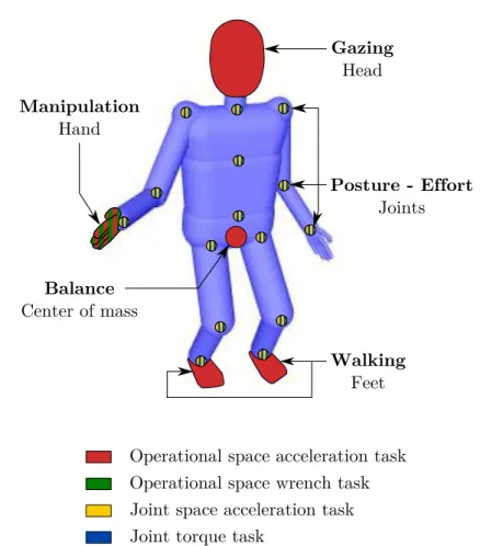
3.2 Tasks included in the manikin controller for simulating manual ac-tivities . . . 46
3.3 General method for motion capture replay . . . 49
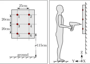
4.1 Geometric dimensions for the drilling activity . . . 60
4.2 Motion and force capture instrumentation for the drilling task. . . . 61
4.3 Human subject and manikin replay for the drilling task . . . 61
4.4 Time evolution of experimental and simulated ground contact forces in the drilling activity . . . 66
4.5 Temporal offset between the experimental and simulated ground con-tact forces . . . 67
4.6 Time evolution of the experimental and simulated positions of the CoP in the drilling activity . . . 68
4.7 Definition of the geometric parameters of the path tracking activity. 72 4.8 Motion and force capture instrumentation for the path tracking ac-tivity. . . 74
4.9 Human subject and manikin replay for the path tracking task . . . . 75
4.10 Variations of the position indicator for the path tracking activity depending on the geometric parameters . . . 78
4.11 Variations of the position indicator for the path tracking activity depending on the force and time parameters . . . 79
4.12 Variations of the torque indicator for the path tracking activity de-pending on the geometric parameters . . . 80
4.13 Variations of the torque indicator for the path tracking activity
de-pending on the force and time parameters . . . 81
4.14 Variations of the power indicator for the path tracking activity . . . 82
4.15 Kinematic structure of the simulated collaborative robot . . . 85
4.16 Simulation of a human-cobot activity. . . 86
4.17 Evolution of the right arm torque indicator in a co-manipulation activity, with and without fatigue consideration . . . 91
5.1 Flow chart of the method for the sensitivity analysis of ergonomic indicators . . . 104
5.2 Abstraction of the collaborative robot by a mass-spring-damper . . . 105
5.3 Scree plot for selecting relevant ergonomic indicators . . . 111
5.4 Ergonomic indicators identified as relevant based on their variance, for various activities . . . 115
5.5 Values of the most influential parameters associated with the extreme values of the ergonomic indicator . . . 116
5.6 Simulation of a trajectory tracking activity in different situations.. . 117
5.7 Discriminating Ergonomic indicators for each time step of a walking then reaching activity . . . 123
6.1 Genetic algorithm general scheme . . . 131
6.2 Framework for optimizing a cobot morphology . . . 132
6.3 Formation of the next parent population with the NSGA-II genetic algorithm . . . 134
6.4 Structure of the genome used to represent the morphology of a col-laborative robot. . . 137
6.5 Regular crossover operator. . . 138
6.6 Modified crossover operator . . . 139
6.7 Continuous mapping of the joint type . . . 142
6.8 Evolution of the objectives values in the Pareto front during the optimization of the cobot morphology . . . 149
6.9 Evolution of the objectives values in the population during the opti-mization of the cobot morphology. . . 150
6.10 Shortest robot of the Pareto front for the 10th and 220th generations 152 A.1 Definition of back and neck motion . . . 165
A.2 Definition of upper limb motion . . . 166
A.3 Definition of lower limb motion . . . 167
B.1 Kinematic structure of the manikin . . . 170
C.1 ABLE exoskeleton . . . 173
2.1 Specificities of standard methods for ergonomic assessment . . . 17
2.2 DHM software for generic applications . . . 21
2.3 DHM software for specific applications . . . 23
2.4 Detailed biomechanical models software . . . 26
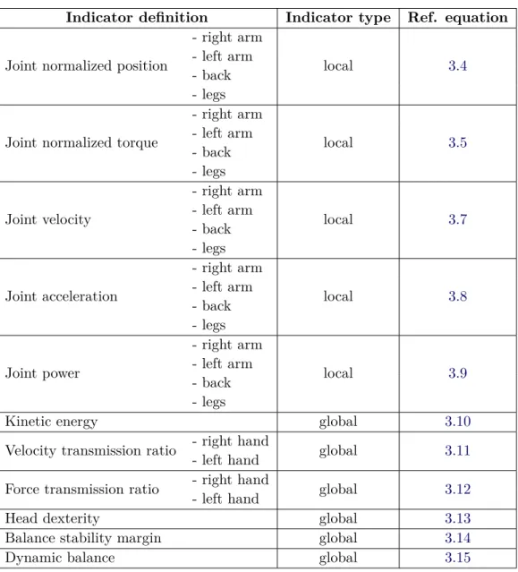
3.1 List of ergonomic indicators . . . 42
4.1 RMS errors between the experimental and simulated positions of the markers in the drilling activity . . . 62
4.2 Correlation between the experimental and simulated ground contact forces in the drilling activity. . . 64
4.3 RMS error between the experimental and simulated ground contact forces in the drilling activity. . . 65
4.4 Position error between the experimental and simulated CoP in the drilling activity . . . 67
4.5 Values of the geometric parameters of the path tracking activity . . 73
4.6 Values of the time and force parameters of the path tracking activity 73 4.7 Physical features of the human subjects for the path tracking activity 75 4.8 Correlation between the strenuousness and the ergonomic indicators for the path tracking activity . . . 77
4.9 Influence of the robot kinematic parameter on the ergonomic indica-tors during contact force exertion . . . 88
4.10 Influence of the robot kinematic parameter on the ergonomic indica-tors during free space motions . . . 88
4.11 Influence of the robot dynamic parameter on the ergonomic indica-tors during free space motions . . . 89
4.12 Influence of the robot control parameter on the ergonomic indicators during force exertion . . . 89
4.13 Influence of the robot control parameters on the ergonomic indicators during both force exertion and free space motions. . . 92
4.14 Influence of the robot dynamic parameter on the ergonomic indica-tors during both force exertion and free space motions. . . 92
5.1 Parameters minimum and maximum values for the sensitivity
anal-ysis of ergonomic indicators . . . 113
5.2 Sobol indices for the kinetic energy indicator in the walking sideways activity . . . 118
5.3 Sobol indices for the right arm joint acceleration indicator in the fast trajectory tracking activity . . . 119
5.4 Sobol indices for the right arm joint torque indicator in the pushing activity . . . 119
5.5 Sobol indices for the left arm joint torque indicator in the bending activity . . . 120
5.6 Sobol indices for all five relevant ergonomic indicators in the drilling activity . . . 126
6.1 Genetic algorithm parameters for the drilling activity. . . 147
6.2 Genome parameters for the drilling activity . . . 148
6.3 Comparison of robots performances at the beginning and at the end of the optimization.. . . 151
6.4 Comparison of the ergonomic indicators without assistance, and with the assistance of near-optimal cobots for the drilling job.. . . 153
A.1 Human joint limits . . . 168
A.2 Human joint torque capacities . . . 168
B.1 Joints description of the XDE-manikin . . . 169
C.1 Ergonomic indicators without assistance, with weight compensation and with a co-worker robot . . . 177
Introduction
Contents1.1 Work-related musculoskeletal disorders . . . . 2
1.1.1 Cost of work-related MSDs . . . 3
1.1.2 Risk factors for MSDs . . . 4
1.2 Collaborative robotics. . . . 4
1.2.1 Definition . . . 5
1.2.2 Functions of collaborative robots . . . 5
1.3 Human-oriented evaluation of collaborative robots . . . . . 8
1.3.1 Problematic . . . 8
1.3.2 Thesis contents . . . 9
1.3.3 Publications. . . 12
Among the features that characterize the human-being, one of the most distinc-tive is the use of tools, intended for increasing human abilities. Physical abilities can be improved, for instance, by a lever for amplifying forces, a wheelbarrow for carrying heavy loads, or a steam engine for generating thrust. Tools are also used for improving cognitive abilities (e.g. an abacus for performing mathematical oper-ations) or perceptive abilities (e.g. a telescope or a microscope for observing objects which can otherwise not be seen).
Robots are a kind of tool that have initially been thought for replacing humans at work. Indeed the word robot comes from the Czech words robota, meaning work, and robotník meaning worker. Since the second half of the twentieth century, robots have been increasingly used in industrial applications. For instance, pick and place robots allow fast and accurate positioning of various objects, such as electronic components on a circuit board. Palletizers are another example of widely used industrial robots. They have been developed for automatically placing products onto pallets, an activity which is tiring and time-consuming for a human-being.
Such industrial robots are fully automated and programmed to do repetitive tasks with very limited human intervention.
In some situations however, the human cognitive and perceptive abilities are needed to carry out the task. Tele-operated robots address this problem with a master-slave system. The slave robot copies the movement of the master system controlled by a human operator. This is particularly useful for situations in which the operator cannot enter the work environment, such as maintenance operations in nuclear core facilities. More recently co-manipulated systems have been developed, in which the robot and the operator physically interact for carrying out the task. Such systems combine the physical abilities of the robot with the reasoning abilities of the operator. Hence they are increasingly used for providing assistance to the operator in physically demanding and complex tasks. As such, co-manipulated sys-tems are a potential solution to the growing problem of work-related musculoskeletal disorders.
1.1
Work-related musculoskeletal disorders
Musculoskeletal disorders (MSDs) are injuries or pain that affect the body’s muscles, joints, tendons, ligaments or nerves. Examples of common MSDs are tendinitis, bursitis, carpal tunnel syndrome, and back pains (Fig. 1.1). They occur when biomechanical solicitations at work exceed the worker’s physical capacity, both in terms of intensity and frequency [Luttmann 2003, Aptel 2011], and result in pain, but also in joint stiffness, clumsiness and loss of force.
Wrist, Hand
Carpal tunnel syndrome Shoulder
Rotator cuff tendinitis
Knee Bursitis Elbow Epicondylitis Ankle Achilles tendinitis Back
Low back pain Neck
Tension neck syndrome
Figure 1.1: Most frequent work-related MSDs. Circle size qualitatively represents the global cost of the corresponding MSD, i.e. average unit cost multiplied by the number of reported cases (adapted from ARACT Ile de France1
).
1.1.1 Cost of work-related MSDs
Though working conditions have improved in developed countries, work-related MDSs remain a major health problem. They account for the majority of reported occupational diseases (59 % in Europe, 75 % in France in 2005) and affect almost 50 % of industrial workers [Schneider 2010]. In France, according to the CNAMTS (Caisse Nationale d’Assurance Maladie des Travailleurs Salariés), MSDs caused 8.4 M lost workdays in 2013, which represent a direct cost of 1.5 Be (medical ex-penses and workers’ compensation covered by companies contributions), plus pro-ductiveness loss due to turnover and hiring difficulties. In the US, the Bureau of Labor Statistics estimated the direct cost of MSDs at 20 B$ per year, and the total cost between 45 and 54 B$ per year [NRC 2001]. Hence reducing MSD is a high-stakes socio-economic issue.
Besides, the number of reported MSDs has been significantly growing in the last decades. In Europe, they increased by 32 % from 2002 to 2005. In France, despite a recent slowdown in the progression, the yearly number of reported MSDs has been multiplied by ten between 1993 and 2013 (Fig.1.2). The exact underlying causes of this significant increase are not well established. However, besides a better recog-nition of these diseases, a possible explanation can be found in the changes in work organization. On one hand, just-in-time, tight flow or zero inventory production systems require a rather constant workload. On the other end, due to partially automated productions and high economic stress, companies tend to demand in-creasing work rate and productiveness, therefore pushing their employees to their physical limits. Progression of MSDs in France 40000 2001 1999 1997 1995 1993 2003 2005 2007 2009 30000 20000 10000 0 2011 2013 50000 39874 37728 33682 30968 29379 28278 24334 23672 21126 15912 13394 11995 8972 7395 5856 4773 3963 3165 43359 42148 40613
Figure 1.2: Yearly number of reported occupational diseases corresponding to the French health insurance table 57 "Periarticular illness caused by work postures and movements"2
.
2http://www.risquesprofessionnels.ameli.fr/statistiques-et-analyse/
1.1.2 Risk factors for MSDs
The causes of MSDs are often multi-factorial and include different kinds of factors: • personal: age, gender...;
• organizational: working time, frequency and duration of breaks...; • psychosocial: job decision latitude, social support from co-workers...;
• biomechanical (see examples on Fig. 1.3): awkward postures, high forces, static postures, repetitive work (and to a lesser extent: vibration, tempera-ture, contact stress and gloves wearing).
The biomechanical factors represent the physical solicitations to which the worker is exposed. They are the major risk factors, especially when they are combined together. However their combination with other kinds of factors increases the risk of developing MSDs, since personal, organisational, and psychosocial factors affect a person’s physical capacity.
Figure 1.3: Examples of work situations that could cause MSDs (pictures from the INRS website3
). Left: awkward posture associated with significant force. Right: static work.
1.2
Collaborative robotics
Since MSDs result from strenuous biomechanical solicitations, replacing men by robots to accomplish hard tasks might be considered an option in order to decrease the number of MSDs. Thanks to the significant development of automation in industry during the last century, some human related limits have been overcome. However as of today, many hard tasks cannot be fully automatized (at all or at reasonable costs): because of their unpredictability and/or technicality, they still require human expertise (e.g. high standing and job lot automotive production, mass customization).
1.2.1 Definition
A solution to decrease MSDs in complex tasks is to assist the worker with a collab-orative robot, rather than replacing him. A collabcollab-orative robot enables the joint manipulation of objects with the worker (co-manipulation) and can thereby be used to alleviate the worker’s physical load. This new approach combines the qualities of both humans and robots: the worker brings his job expertise and decision-making skills whereas the robot brings its positioning accuracy and capacity to generate high forces.
Though the generic term for such devices is Intelligent Assist Devices (IADs) [Colgate 2003], they are often called cobots (portmanteau of collaborative robots). The word cobots was proposed by Colgate and Peshkin in 1996 to refer to wheeled robots using computer-controlled steering of wheels to guide motion in shared ma-nipulation [Colgate 1996]. Despite its very specific initial meaning, the word cobot is now often used to refer to any robot for direct physical interaction with a human operator, within a shared workspace.
Collaborative robots can be classified into three families: parallel, serial and orthotic co-manipulation. When the human manipulates the robot by its end-effector, the human-robot system forms a parallel kinematics system, therefore the co-manipulation is said to be parallel. When the human-robot interaction is distributed in multiple points, the manipulation is orthotic. Orthotic co-manipulators are also called exoskeletons. Finally serial co-manipulation refers to hand-held devices, since the human-robot system then forms a serial kinematic chain.
1.2.2 Functions of collaborative robots
Collaborative robots provide a variety of benefits such as weight compensation, inertia masking, strength amplification, and guidance via virtual surfaces and paths [Colgate 2003]. These functions aim at reducing two of the main biomechanical risk factors for MSDs:
• High forces: Part of the forces resulting from the interaction with the tool or environment are supported by the robot, therefore reducing the worker effort in power tasks. Moreover, by reducing or eliminating some external force disturbances, the robot decreases the control effort required from the worker in high precision tasks.
• Awkward postures: Posture improvement can be a consequence of reduced effort. The posture can also be modified by setting the user-robot interaction port away from the tool, thus requiring smaller gestures from the worker to reach the work area.
Others functions, such as amplification of force feedback and tremor filtering, can be provided to facilitate fine manipulation [Erden 2011]. However they do not directly address the problem of MSDs, and therefore will not be considered in this work.
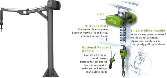
Weight compensation: Weight compensation is used in manual handling jobs. It consists in cancelling the vertical component of the load gravity wrench, and was first proposed by Powell in 1969 with the Tool Balancer [Powell 1969]. The load is hung up to a variable-length cable, and in current systems its vertical manipulation is power-assisted thanks to a force sensor set on the user handle (Fig.1.4).
Figure 1.4: Weight compensation systems enabling manual handling of heavy loads. Left: Free Standing Easy ArmTM, Gorbel. Right: iLiftTM, Stanley Assembly
Tech-nologies.
Inertia masking: Inertia masking consists in reducing the starting, stopping, and turning forces when manipulating a load, and ensuring that motions in all di-rections respond equally to human input. This function is used for manual shifting of heavy objects. Inertia masking can be achieved by the computer-controlled steer-ing of wheeled robots (based on virtual surfaces). The load is set on a trolley, which wheels orientation is automatically adapted depending on the force applied by the user. The inertia effects experienced by the user during speed or direction changes are therefore reduced. This function was proposed by Colgate and Peshkin in the
Scooter cobot (Fig. 1.5) [Peshkin 2001]. The iTrolley (Stanley Assembly
Tech-nologies), which is an addition to the iLift weight compensation system, is another example of inertia masking system. The inertial effects of the load are compensated by a servo-controlled trolley and a measure of the cable deviation from vertical.
Strength amplification: Strength amplification consists in controlling the robot so that the force it exerts on the manipulated tool (or environment) is an ampli-fied image of the force applied by the worker onto the robot. This function was first implemented during the Hardiman project (General Electrics) [Groshaw 1969]. The system was based on force feedback tele-operation: it consisted of two in-terlocked anthropomorphic manipulators, one (master) physically attached to the
Figure 1.5: Scooter cobot: virtual paths are implemented thanks to the computer-controlled steering of the three wheels, in order to reduce inertia effects in direction changes.
user, the other (slave) following the user motions while exerting amplified efforts on the environment. This concept was later modified in the Extender project by removing the master robot, the user thus directly interacting with the slave robot [Kazerooni 1993].
Today, exoskeletons probably are the most famous strength amplification sys-tems [Bogue 2009], e.g. HULC (Human Universal Load Carrier) (Ekso Bion-ics), or Hercule (RB3D, CEA-LIST). These two systems are designed to help the user carry heavy loads without limiting his/her displacements. However non-orthotic strength amplification systems also exist. For instance, the HookAssist (Kinea Design) designed for beef boning (Fig. 1.6 left) [Santos-Munne 2010], or the Cobot 7A.15 (RB3D, CEA-LIST, CETIM) which was first designed for tire retreading, but has now been adapted for various machining jobs (Fig. 1.6 right). Strength amplification has also been implemented on generic industrial manipula-tors [Lee 2006,Lamy 2011].
Figure 1.6: Collaborative robots providing strength amplification. Left: HookAssist (Kinea Design) for beef boning. Right: Cobot 7A.15 (RB3D, CEA-LIST, CETIM) for tire retreading or machining.
Guidance via virtual surfaces and paths: Motion guidance consists in limit-ing the end-effector degrees of freedom by hardware or software means, so that the tool can only perform specific motions [Book 1996]. The human technical gesture thus gains in speed and accuracy, while requiring less co-contraction effort. The cognitive load associated with the task is also reduced.
1.3
Human-oriented evaluation of collaborative robots
The afore-mentioned functions cover a wide range of applications, therefore more and more sectors are interested in collaborative robotics - or cobotics - to address the MSDs problem: automotive and aeronautics industries, food-processing industry... Each application, even within the same sector, involves specific features (gesture, force range, workspace organization...), which are as many constraints for both the worker and the cobot. Therefore the efficiency of a cobot regarding the reduction of MSDs risks is highly task-dependent. Yet, even when designing dedicated systems, the ergonomic benefit provided by the cobot is hardly ever quantitatively evaluated, because of the lack of relevant assessment tools.1.3.1 Problematic
The purpose of this work is to develop a methodology to quantitatively compare the ergonomic benefit provided by different collaborative robots when performing a given task. The word ergonomy refers here to biomechanical factors only. Other factors (see section 1.1.2) are not considered, even if they can be affected by the use of a cobot (e.g. worker’s perception of his work).
The proposed methodology relies on an evaluation carried out within a digital world, using a virtual manikin to simulate the worker. Indeed, the digital evaluation presents several major advantages over a physical evaluation. Firstly, the simulation enables easy access, through the manikin, to detailed biomechanical quantities, which cannot be measured on real humans, or only with heavy instrumentation (e.g. muscle or joint forces). Secondly, thanks to the simulation, the collaborative robot can easily and quickly be tested with many different morphologies of workers, without the need for a wide variety of real workers. Thirdly, a virtual - instead of a physical - mock-up of the robot is used for digital ergonomic assessments. Assessments of the cobot-worker system can thus easily be performed very early, and then all along, the design process. The cost of building a new prototype every time a parameter of the robot is tuned is removed: a virtual mock-up can be more easily modified. Therefore, when integrated in a design process, the simulation potentially decreases the overall development time and cost of a collaborative robot.
The methodology presented in this work focuses on collaborative robots dedi-cated to power tasks, i.e. tasks requiring significant effort. Precision tasks are not addressed. More specifically, only parallel co-manipulation robots which provide strength amplification are considered. Among the functions that can be used to
reduce MSDs risk in power tasks, strength amplification is particularly interesting, because it addresses a wide range of applications, and in particular jobs requiring hand-held tools (e.g. machining, boning...). On the contrary, weight compensa-tion and inertia masking are limited to material handling jobs. Due to this fo-cus on power tasks, serial co-manipulation are excluded from this work. Serial co-manipulation devices for MSDs reduction do exist (e.g. electric power screw-drivers), however these hand-held devices are not adapted to power tasks. When significant forces are involved, the cobot need powerful actuators which are usually heavy, hence a heavy structure. So if the worker is carrying the cobot, this one be-comes a cause of MSDs because of its weight. The same criticism applies to entirely wearable orthotic robots. Nevertheless, most parts of the methodology proposed in this work can still be extended to other kinds of collaborative robots (functions and/or structure).
1.3.2 Thesis contents
In this work, a novel approach for evaluating collaborative robots through simu-lation is proposed. This approach is based on the association of a framework for exhaustive measurement of biomechanical solicitations, with an analysis method for selecting relevant comparison criteria. The whole methodology is summarized in Fig.1.7. The organization of this thesis is detailed hereafter.
Chapter 2 first presents the requirements of an ergonomic evaluation for co-manipulation activities. Given these requirements, the various evaluation methods and digital human model (DHM) software tools that are currently used for er-gonomic evaluations are reviewed. However none of them fully match the expected requirements. The tools used for workstation design provide a few ergonomic indi-cators that are very rough and/or do not cover all kinds of manual activities. The tools used for biomechanical studies provide a high number of measurements which interpretation - both in terms of reliability and task-related relevance - requires specific biomechanical knowledge. Therefore, a novel approach situated in between the existing ones is proposed. This approach combines a framework for measuring numerous detailed ergonomic indicators, with an analysis method to identify the most relevant indicators for a given task.
The framework developed for measuring biomechanical solicitations during co-manipulation activities is presented in chapter 3. This measurement framework is based on a high level representation of the human body (no muscles), and con-sists of two components: a list of ergonomic indicators, and a simulation tool. Ergonomic indicators which match the requirements of collaborative robotics are defined. Such indicators account for the different biomechanical solicitations which occur during manual activities, performed with or without the assistance of a col-laborative robot. The proposed list contains sufficiently diverse indicators so as
C hapter 1. In tro duction Chapter 4 Validation Chapter 3
Motion capture and dynamic replay Ergonomic indicators for manual activities
Virtual human simulation of co-manipulation activities Tools
Worker performing a non-assisted activity
Task description
Relevant ergonomic indicators
Validated cobot Reference situation Chapter 5 Sensitivity analysis of ergonomic indicators Chapter 2
Review of ergonomic tools
Optimization of cobots morphology Chapter 6 Comparison of different cobots Differential ergonomic assessment
...
...
ApplicationsValidated workstation ... ... Validated cobot
re 1.7: Ov ervie w of the me th odology de ve lop ed for p erforming ergon omic as -nts of collab orativ e rob ots . Th ou gh this w ork fo cus es on collab orativ e rob ots ation , th e to ols an d me tho ds that are de ve lop ed can als o b e us ed -with sligh t ifi cation s -for a wide r ran ge of ap plic ation s, su ch as the ev aluation of w orks ta-s, or oth er kin d s of as sis tiv e de vic es .
to cover all kinds of manual activities as exhaustively as possible (excluding pre-cision tasks). The measurement of the proposed ergonomic indicators requires the simulation of the activity with a virtual manikin. Therefore a framework for the dy-namic simulation of co-manipulation activities is implemented. A virtual manikin is animated through standard optimization techniques in order to automatically perform all kinds of manual activities with the assistance of a collaborative robot. Any parallel co-manipulation robot for strength amplification can be used in the simulation. Finally a method for dynamically replaying pre-recorded motions with the virtual manikin is proposed. This method is developed mainly for validation purposes, detailed in the next chapter.
Chapter 4 presents a validation of the measurement framework presented in the previous chapter. Two motion capture based experiments are carried out in order to estimate the realism of the manikin model, and the consistency of the proposed ergonomic indicators. Then a fully automatic simulation is implemented on a sim-ple task in order to validate the reliability and usefulness of the manikin-robot simulation. The results obtained in all three experiments are mostly satisfying, and validate the methodology proposed for biomechanical measurements during co-manipulation activities. However, the results also highlight several limitations which may affect the validity of the measurements. These limitations, mostly re-lated to the manikin model and control, are discussed.
Chapter5presents a method for selecting relevant comparison criteria for a given task, among all the proposed ergonomic indicators. In order to facilitate the inter-pretation of the results when comparing different collaborative robots, the number of ergonomic indicators that are considered must be limited. Yet the remaining indicators must sufficiently account for the global ergonomic level of the task. The proposed method is based on the analysis of the sensitivity of the ergonomic in-dicators to the robot and task parameters. In order to conduct such an analysis, the indicators must be measured, for each new task, in many different conditions,
i.e. with the assistance of many different cobots. Therefore a framework for such
an evaluation is implemented. It is based on the simulation tool described in chap-ter3, associated with a dedicated representation of collaborative robots, and stan-dard methods for the design of experiments. The proposed method is validated on various simple tasks, and applied to an industrial drilling job.
Finally, chapter 6 presents an application of the proposed methodology to the optimization of the cobot morphology. The ergonomic indicators analysis method presented in chapter 5 is used to select relevant optimization criteria (objectives). Then the simulation framework presented in chapter3is linked to a multi-objective genetic algorithm software for the optimization. The genetic algorithm is used for exploring the space of robot morphologies, i.e. providing robot candidates to be evaluated. The simulation tool is used for numerically estimating the various
ob-jectives for each robot candidate. The proposed optimization framework is applied to optimize a cobot for a drilling job.
1.3.3 Publications
Beyond the specific application to the evaluation of collaborative robots, this work has a wider ambition. It aims at developing a generic tool for performing accurate ergonomic assessments of dynamic situations with very little input data, contrarily to existing tools which generally require much input data in order to perform accu-rate evaluations. The development of such a tool requires three main components: 1. Accurate and generic measurements of the biomechanical solicitations
expe-rienced by the manikin/worker.
2. A physically consistent dynamic simulation with an autonomous virtual manikin, in which scenarii can easily be created and automatically simulated.
3. A tool for automatically evaluating the relevance of the ergonomic measure-ments, in regard to each specific situation.
All these components are presented in this thesis, and have been published in three international conferences, listed hereafter:
P. Maurice, Y. Measson, V. Padois, and P. Bidaud. Experimental assessment of
the quality of ergonomic indicators for collaborative robotics computed using a dig-ital human model. 3rd Digdig-ital Human Modeling Symposium, 2014 (component 1,
chapters 3and 4)4.
P. Maurice, Y. Measson, V. Padois, and P. Bidaud. Assessment of physical
ex-posure to musculoskeletal risks in collaborative robotics using dynamic simulation.
CISM International Centre for Mechanical Sciences, Romansy 19 - Robot Design, Dynamics and Control. Vol 544 Pages 325-332, 2013 (component 2, chapter 4)5
.
P. Maurice, P. Schlehuber, V. and Padois, P. Bidaud, and Y. Measson. Automatic
selection of ergonomic indicators for the design of collaborative robots: a virtual-human in the loop approach. IEEE-RAS International Conference on Humanoid
Robots, 2014 (component 3, chapter 5)6
.
4https://hal.archives-ouvertes.fr/hal-00971319/document 5https://hal.archives-ouvertes.fr/hal-00720750/document 6https://hal.archives-ouvertes.fr/hal-01072228/document
Review of ergonomic tools
Contents2.1 Ergonomic assessment methods for workplace evaluation . 14
2.1.1 Observation-based methods . . . 15 2.1.2 Physical limit recommendations. . . 15 2.1.3 Standard . . . 15 2.1.4 Limitations . . . 16 2.2 Virtual manikins for workplace design . . . . 18
2.2.1 General features . . . 19 2.2.2 Common DHM software . . . 19 2.2.3 Manikin animation . . . 22 2.2.4 Conclusion . . . 24 2.3 Detailed biomechanical models . . . . 24
2.3.1 General features . . . 24 2.3.2 Common biomechanical models . . . 25 2.3.3 Model animation . . . 25 2.3.4 Conclusion . . . 27 2.4 Ergonomic assessment of robot-worker collaboration . . . . 28
2.4.1 State of the art . . . 28 2.4.2 Proposed approach . . . 29
The work presented in this thesis aims at developing a tool which enables the comparison, through simulation, of the ergonomic benefit provided by various col-laborative robots. Such a tool must match the specific requirements of colcol-laborative robots evaluation. These requirements can be divided in two families: those related to the evaluation metric, and those related to the simulation tool. The requirements related to the evaluation metric are the following:
• The activities that can be addressed by collaborative robotics are diverse, so the evaluation criteria must cover all kinds of manual activities.
• The evaluation of a collaborative robot must take the whole task execution into account, and not only the phases in which the robot is expected to assist the worker. Indeed, an ill-adapted robot can cause new MSDs, thus not improving (and possibly worsening) the overall ergonomic situation. The dynamic phases are especially important since the negative effects of the robot are likely to be more significant in those phases.
• All parts of the human body must be considered in the evaluation, and not only those initially affected by MSDs. An ill-adapted cobot may delocalized the MSDs risk to other body parts, instead of reducing the overall risk. • The interpretation of the results must be straightforward, because the tool
developed in this work is intended for robot designers rather than for biome-chanics specialists.
The goal of the simulation tool is to enable the estimation of the measurements included in the evaluation metric. Therefore the requirements related to the simu-lation tool are closely linked to those related to the evaluation metric:
• The simulation framework must ensure the physical consistency of all mea-surements, especially the dynamic ones.
• The motion of the manikin must be realistic, otherwise the results of the ergonomic assessment are not reliable.
• The motion of the manikin must be automatically generated, otherwise the development of each simulation is much more time consuming.
• The simulation tool must enable the simulation of co-manipulation activities,
i.e. of a virtual manikin physically interacting with a collaborative robot.
This chapter therefore reviews the existing ergonomic tools (evaluation meth-ods and simulation software), in order to check whether or not they match the requirements cited above. Then, the approach proposed in this work is detailed.
2.1
Ergonomic assessment methods for workplace
eval-uation
Due to the growing number of MSDs, and in order to improve the design of work-places, various methods have been developed to assess the biomechanical risks associated with an activity. These methods can be classified into two families: posture-based methods for risk evaluation, and physical limit recommendations [Li 1999,David 2005].
2.1.1 Observation-based methods
The first family of methods consists of posture-based methods, which require the observation of a worker performing the task. They are often grids or check-lists that assign a score to the activity for each one of the main MSDs factors: posture, effort, duration and frequency of the task, and sometimes for additional factors such as vibrations, temperature, or gloves-wearing. They result in a estimation of an absolute level of risk (e.g. acceptable, not recommended, unacceptable) indicating whether changes in the workplace organization should be investigated.
The most widely known methods are the Owako Working Posture Analysis System (OWAS) [Karhu 1981], the Rapid Upper Limb Assessment (RULA, Fig.2.1) [McAtamney 1993], the Rapid Entire Body Assessment (REBA) [Hignett 2000], the Occupational Repetitive Action index (OCRA) [Occhipinti 1998], the OSHA checklist [OSHA 1999], and the Strain Index [Moore 1995].
2.1.2 Physical limit recommendations
The second family of methods consists of equations or tables that give physical limits not to exceed in order to minimize the MSDs risk during manual handling operations. The most widely used are the NIOSH (National Institute for Occupa-tional Safety and Health) equation [Waters 1993], and the Liberty Mutual Manual Material Handling tables (or Snook and Ciriello tables) [Snook 1991].
The NIOSH equation provides a recommended weight limit for lifting tasks, based on the height and distance of the load to the body, the vertical displace-ment of the load, the upper body twisting angle, the frequency and duration of lifts, and the quality of grasp. The Liberty Mutual tables consider approximately the same factors, but they provide the population percentage able to perform lift-ing/lowering/pushing/pulling/carrying tasks, for various load weights.
2.1.3 Standard
Given the number of ergonomic assessment methods, the French standardization agency issued a document in order to guide designers. The french standard EN NF 1005 "Safety of machinery - Human physical performance" relies on several meth-ods to provide recommendations about MSDs risks evaluation for various manual activities [AFNOR 2008a]:
• 1005-2: manual handling of objects weighting more than 3 kg, displaced less than 2 m (NIOSH lifting equation),
• 1005-3: static pushing and pulling jobs,
• 1005-4: postural evaluation for tasks with no external load,
C hapter 2. Rev iew of ergonomic to ols 1 2 3 4 5 6 7+ 1 1 2 3 3 4 5 5 2 2 2 3 4 4 5 5 3 3 3 3 4 4 5 6 4 3 3 3 4 5 6 6 5 4 4 4 5 6 7 7 6 4 4 5 6 6 7 7 7 5 5 6 6 7 7 7 8+ 5 5 6 7 7 7 7 Table C SCORES Table A
RULA Employee Assessment Worksheet
Subject: Date: / /
Company: Department: Scorer:
Step 1a: Adjust…
Step 1: Locate Upper Arm Position
A. Arm & Wrist Analysis B. Neck, Trunk & Leg Analysis
20o+
Step 13: Add Muscle Use Score
Step 14: Add Force/load Score
Step 15: Find Column in Table C
+
=
+
Step 9: Locate Neck Position
Step 9a: Adjust…
If legs & feet supported and balanced: +1; If not: +2
If trunk is twisted: +1; If trunk is side-bending: +1 If neck is twisted: +1; If neck is side-bending: +1
Use values from steps 8,9,& 10 to locate Posture Score in Table B
If posture mainly static or; If action 4/minute or more: +1
If load less than 2 kg (intermittent): +0; If 2 kg to 10 kg (intermittent): +1; If 2 kg to 10 kg (static or repeated): +2; If more than 10 kg load or repeated or shocks: +3
= Force/load Score
= Final Neck, Trunk & Leg Score = Muscle Use Score = Posture B Score
= Final LegScore = Final Trunk Score
Table B
10o to 20o
0o to 10o
in extension
Complete this worksheet following the step-by-step procedure below. Keep a copy in the employee's personnel folder for future reference.
+1 +2 +3 +4 +1 +2 20o to 60o +3 +4 60o+ 0o to 10o 0o to 20o standing erect seated - 20o 1 also if trunk is well sup-ported while seated; 2 if not
Step 10: Locate Trunk Position
Step 10a: Adjust…
Step 11: Legs
Final Score= Step 2: Locate LowerArm Position
Final Lower Arm Score =
+
If wrist is bent from the midline: +1
Step 6: Add Muscle Use Score
Step 7: Add Force/load Score
If load less than 2 kg (intermittent): +0; If 2 kg to 10 kg (intermittent): +1; If 2 kg to 10 kg (static or repeated): +2; If more than 10 kg load or repeated or shocks: +3
=
The completed score from the Arm/wrist
analysis is used to find the row on Table C Final Wrist & Arm Score = Step 3: Locate Wrist Position
Step 3a: Adjust…
+1 +1 +1 +1 +1 +3 +1 +1 +2 +2 15o+ 0o to 15o +3 15o+ 0o to 15o
Step 2a: Adjust…
If arm is working across midline of the body: +1; If arm out to side of body: +1
Final Upper Arm Score = +20o to 45o > -20o +2 +1 +45o to 90o 90o+ +3 +4 +2
Final Wrist Score =
Wrist Twist Score =
Upper Lower
Wrist
Arm Arm
1 2 3 4 Wrist TwistWrist Twist Wrist Twist Wrist Twist
1 2 1 2 1 2 1 2 1 1 1 2 2 2 2 3 3 3 2 2 2 2 2 3 3 3 3 3 2 3 2 3 3 3 4 4 2 1 2 2 2 3 3 3 4 4 2 2 2 2 3 3 3 4 4 3 2 3 3 3 3 4 4 5 3 1 2 3 3 3 4 4 5 5 2 2 3 3 3 4 4 5 5 3 2 3 3 4 4 4 5 5 4 1 3 4 4 4 4 4 5 5 2 3 4 4 4 4 4 5 5 3 3 4 4 5 5 5 6 6 5 1 5 5 5 5 5 6 6 7 2 5 6 6 6 6 7 7 7 3 6 6 6 7 7 7 7 8 6 1 7 7 7 7 7 8 8 9 2 7 8 8 8 8 9 9 9 3 9 9 9 9 9 9 9 9 Upper Lower Arm Arm
Step 5: Look-up Posture Score in Table A Step 4: Wrist Twist
If wrist is twisted mainly in mid-range =1; If twist at or near end of twisting range = 2
+
Posture Score A =Force/load Score =
FINAL SCORE: 1 or 2 = Acceptable; 3 or 4 investigate further; 5 or 6 investigate further and change soon; 7 investigate and change immediately
If shoulder is raised: +1; If upper arm is abducted: +1; If arm is supported or person is leaning: -1
If posture mainly static (i.e. held for longer than 1 minute) or; If action repeatedly occurs 4 times per minute or more: +1
Step 8: Find Row in Table C
Muscle Use Score =
=Final Neck Score
The completed score from the Neck/Trunk & Leg analysis is used to find the column on Chart C
Step 12: Look-up Posture Score in Table B
e r o c S e r u t s o P k n u r T 1 2 3 4 5 6 s g e L Legs Legs Legs Legs Legs k c e N 1 2 1 2 1 2 1 2 1 2 1 2 1 1 3 2 3 3 4 5 5 6 6 7 7 2 2 3 2 3 4 5 5 5 6 7 7 7 3 3 3 3 4 4 5 5 6 6 7 7 7 4 5 5 5 6 6 7 7 7 7 7 8 8 5 7 7 7 7 7 8 8 8 8 8 8 8 6 8 8 8 8 8 8 8 9 9 9 9 9
Source: McAtamney, L. & Corlett, E.N. (1993) RULA: a survey method for the investigation of work-related upper limb disorders, Applied Ergonomics, 24(2) 91-99. © Professor Alan Hedge, Cornell University. Feb. 2001
-20o to +20o
0o
Use values from steps 1,2,3 & 4 to locate Posture Score in table A -60o to 100o +1 100o+ 0-60o +2 +2 re 2.1: F orm u se d to es timate the le ve l of MS Ds ris k ac cording to th e Rap id er Lim b As se ss me nt me tho d. Limitations ite th is wid e varie ty of ergon omic as se ss me nt me tho ds , all ha ve some fe ature s h mak e th em u n su itable for the ev aluation of a job p erforme d with a coll ab o-e rob ot. Th eir limitation s are de tail ed he re af te r.
Lack of precision regarding force consideration: Several methods, particu-larly the posture-based ones, are not very accurate regarding the force factor. It is calculated based on the magnitude (and possibly direction) of the external force, but it is not affected by the posture (e.g. RULA assessment form step 7 or 14 in Fig. 2.1). However, in order to accurately evaluate the effect of an external force on the musculoskeletal system, the repartition of the effort among joints - which depends on the posture - must be considered.
Specificity regarding applications: Among the afore-mentioned methods, most of them are not generic: they are specific either to a type of activity and/or to a body part (see Table 2.1, and section 2.1.3). But the activities which may be ad-dressed by collaborative robots are various and often complex, consisting of a mix and/or succession of several elementary tasks. Therefore the evaluation of the entire activity is very likely to require the use of several methods together. This raises two problems:
• The choice of the appropriate method to evaluate an elementary task is not always straightforward. There might be no method corresponding exactly to the features of the considered task. In that case, even if a closely-related method is used, this could lead to wrong results.
• The results of the afore-mentioned assessment methods are mostly not homo-geneous. Even when considering only posture-based methods, output scores cannot be compared from one method to another [Li 1999]. Therefore, if dif-ferent methods are used to evaluate different phases of the activity, no global score (i.e. for the whole activity) can be computed.
Posture-based risk assessment
Method Body part considered Jobs considered
OWAS Whole body Non-specific
RULA Upper limb Sedentary jobs
REBA Whole body Non-sedentary jobs
OCRA Upper limb Repetitive jobs
Strain Index Distal upper extremity Non-specific OSHA Check-list Upper limb Non-specific
Physiological limits recommendations
Method Posture considerations Jobs considered NIOSH Lifting equation Hands height Lifting jobs
Liberty Mutual tables Hands height Manual handling jobs Table 2.1: Specificities of standard methods for ergonomic assessment, regarding the body parts and the jobs considered.
Lack of dynamic consideration: The other, and the major, drawback of the existing observational methods is that they are static, meaning that dynamic phe-nomena are not taken into account. Posture-based methods usually only evaluate a static pose and just add a frequency and duration factor. Even in methods where motions are taken into account (e.g. in material handling evaluations), this consideration is strictly geometric (lifting/lowering... distance). The only methods considering dynamic phenomena are REBA and the Strain Index. However, though REBA is said to be for "dynamic postures evaluation", the dynamic factor is quite rough: it consists in modifying the final score if the "action causes rapid large changes in posture or an unstable base". The Strain Index qualitatively considers the speed of work, but it only applies to hands motions evaluation.
Yet it has been established that fast motions increase the risk of developing MSDs because of the efforts they generate in biological tissues [Marras 1993]. Be-sides, in collaborative robotics, evaluating the dynamic phases of the activity is even more important because the robot is never perfectly backdrivable. Some phenom-ena, especially inertial effects, can be hard to compensate, even with a dedicated control law. In such cases, manipulating the robot requires extra efforts from the worker. If too important, these efforts can cause new MSDs, and worsen the over-all ergonomic situation of the worker. For instance, collaborative robots providing strength amplification are generally powerful thus heavy: they are highly inertial so leaving dynamic stages out of the assessment can lead to an underestimation of the risk.
In order to overcome these limitations, some techniques rely on more advanced instrumentation, e.g. goniometers, accelerometers, and motion capture techniques to accurately measure continuous dynamic motions, force sensors and electromyo-graphy for effort measurement [Li 1999, David 2005]. However, these techniques require heavy instrumentation from the worker, and can hinder his gestures. Be-sides, as for basic observational methods, they require a physical prototype of the workplace, and can therefore not be used at an early stage of the design process.
2.2
Virtual manikins for workplace design
An alternative to physical evaluation is to carry out the evaluation within a digital world. Digital evaluation has been enabled by the development of digital mod-eling tools, which improved workstation design methods in the last twenty years [Claudon 2008]. Today several software providing digital human modeling and ani-mation tools can be interfaced with computer-aided design (CAD) software, thereby enabling the simulation of a human operator in a virtual environment (the virtual operator is also called virtual manikin). Despite the initial additional cost of the simulation due to the development time of the animation, the use of digital human model (DHM) software is widening. Indeed, the final design costs decrease when using the simulation, because modifications are easier and cheaper on the simulated
workstation [Chaffin 2007]. Such tools are now common enough, so that specific standards have been established [AFNOR 2008b].
2.2.1 General features
Digital human model software for workplace evaluation can be described as "exter-nal" macroscopic models: the human body is a rigid-body model, and each joint is controlled by a sole actuator (i.e. they do not include muscle models). Initially, they mainly aimed at checking geometric dimensions of the workspace [Chedmail 2002,
Regazzoni 2014]. Now, they have been enriched with further features so that they can be used for ergonomic assessment [Feyen 2000,Bossomaier 2010]:
• Anthropometric database: The human model is scalable in order to rep-resent the workers diversity (size, mass, male or female...).
• Geometric assessment: The collisions between the human model and the environment are detected. The operator’s field of vision and reach envelope are displayed.
• Ergonomic assessment: Several standard assessment methods are usually included, such as RULA, OWAS, the NIOSH lifting equation, the Liberty Mutual tables... Besides, some software include more detailed analysis, such as computation of joints static effort, energy expenditure, low-back load analysis, fatigue analysis. Though these analyses are biomechanically more meaningful than the standard assessment methods, they still do not consider dynamic phenomena in their computation, or only for very specific tasks.
2.2.2 Common DHM software
The main DHM software can be classified into two families: those for generic ap-plications, and those dedicated to specific applications.
2.2.2.1 DHM for generic applications
The most common DHM software for generic applications are listed below, and their main features are summarized in Table2.2.
• Jack: The development of Jack started in the mid 80s at the Centre for Human Modelling and Simulation of the University of Pennsylvania, and was funded by NASA and the US Army [Blanchonette 2010,Raschke 2004]. It is now distributed by Siemens PLM Software (Plano, TX, USA).
• DELMIA: DELMIA is an evolution of the Safework Pro DHM software, which was first developed at Ecole Polytechnique de Montreal in the 80s. It is now distributed by Dassault Systèmes (Vélizy-Villacoublay, France).
• Process Engineer: Ergoman - Process Engineer was developed in the 90s by DELTA Industrie Informatik GmbH (Fellbach, Germany), in collabora-tion with the Technische Universität Darmstadt [Schaub 1997]. It is now distributed by Dassault Systèmes.
• SAMMIE: SAMMIE (System for Aiding Man-Machine Interactive Evalua-tion) was first developed by the Universities of Nottingham and Loughborough at the end of the 70s [Porter 2004]. It is currently distributed by SAMMIE CAD Ltd (Loughborough, UK).
• HumanCAD: HumanCAD was initially developed as MANNEQUINPRO, and is currently distributed by NexGen Ergonomics Inc (Pointe Claire, Québec, Canada).
2.2.2.2 DHM for specific applications
The most common DHM software for specific applications are listed below, and their main features are summarized in Table2.3
• 3DSSPP: The development of 3DSSPP (3D Static Strength Prediction Pro-gram) started in the 90s at the Center for Ergonomics of the University of Michigan [Chaffin 1997]. It is not exactly a DHM software for workplace design, in the sense that no virtual environment is simulated. However it predicts static strength requirements for manual handling tasks such as lifts, presses, pushes, and pulls.
• RAMSIS: The development of RAMSIS (Realistic Anthropological Mathe-matical System for Interior comfort Simulation) started in 1987 at the Tech-nische Universität München, in collaboration with the Techmach company, and was funded by a consortium of automotive designers [Seidl 2004]. It is now distributed by Human Solutions GmbH (Kaiserslautern, Germany). It is dedicated to vehicle interior design (cars, trucks, planes...).
• BHMS: BHMS (Boeing Human Modeling System) has been developed by the Boeing company for aeronautic applications [Rice 2004]. It was initially dedicated to cockpit design, but can now be used for plane assembly and maintenance tasks.
• MAN3D: MAN3D was developed at the Laboratoire de Biomécanique et de Modélisation Humaine de l’IFSTTAR (Lyon, France), in collaboration with Renault, and aims at simulating vehicle ingress motions and driving postures. • IMMA: IMMA (Intelligently Moving Manikins) is a project of the
Fraunhofer-Chalmers Research Centre for Industrial Mathematics (Fraunhofer-Chalmers, Sweden) that started in 2009, carried out in collaboration with the vehicle industry in
Virtual manik ins for w ork place design 21 Manik in animation Forward kinematics X X X X X Inverse kinematics X X - X X Predefined behaviors X X - X X
Motion capture X X - under development
-Others Force-influenced - - - -posture prediction General features Reach envelope X X X X X Collision detection X X - X X Field of vision X X X X X Static force X X - - X calculation
Others - Center of mass / - -
-Base of support E rgonomic assessmen t RULA X X - X -OWAS X - - - -NIOSH lifting X X X X X equation Liberty Mutual X X - - -tables Others Fatigue analysis - - - -Low-back analysis Energy expenditure
Table 2.2: Main features of common DHM software for generic applications. Some of these features are not included in the basic version of the software but can be purchased as extra toolboxes.