UNIVERSITÉ DU QUÉBEC
THÈSE PRÉSENTÉE À
L'UNIVERSITÉ DU QUÉBEC
À
TROIS-RIVIÈRES
COMME EXIGENCE PARTIELLE
DU DOCTORAT EN SCIENCES DE L'ÉNERGIE ET DES MATÉRIAUX
PAR
SIYAD UBAlD
SIMULATION FOR INVESTIGATING THE MULTIPHYSICS PERFORMANCE OF A
CRYO-ADSORPTIVE HYDROGEN STORAGE RESERVOIR FILLED WITH MOF-5
FOR BULK STORAGE AND DISTRIBUTION APPLICATION
Université du Québec à Trois-Rivières
Service de la bibliothèque
Avertissement
L’auteur de ce mémoire ou de cette thèse a autorisé l’Université du Québec
à Trois-Rivières à diffuser, à des fins non lucratives, une copie de son
mémoire ou de sa thèse.
Cette diffusion n’entraîne pas une renonciation de la part de l’auteur à ses
droits de propriété intellectuelle, incluant le droit d’auteur, sur ce mémoire
ou cette thèse. Notamment, la reproduction ou la publication de la totalité
ou d’une partie importante de ce mémoire ou de cette thèse requiert son
autorisation.
Université du Québec à Trois-Rivières Service de la bibliothèque
Avertissement
L'auteur de ce mémoire ou de cette thèse a autorisé l'Université du Québec
à
Trois-Rivières à
diffuser, à
des fins non lucratives, une copie de son mémoire ou de sa
thèse. Cette diffusion n'entraîne pas une renonciation de la part de l'auteur à
ses
droits de propriété intellectuelle, incluant le droit d'auteur, sur ce mémoire ou
cette thèse. Notamment, la reproduction ou la publication de la totalité ou d'une
partie importante de ce mémoire ou de cette thèse requiert son autorisation.
UNIVERSITÉ DU QUÉBEC
À
TROIS-RIVIÈRES
Cette thèse a été dirigée par:
Richard Chahine, Ph. D.
Université du Québec à Trois-Rivières
Directeur de recherche, grade
Institution à laquelle se rattache l'évaluateur
Pierre Bénard, Ph. D.
Université du Québec à Trois-Rivières
Codirecteur de recherche, grade
Institution à laquelle se rattache l'évaluateur
Jury d'évaluation de la thèse:
Richard Chahine, Ph. D.
Université du Québec à Trois-Rivières
Prénom et nom, grade
Institution à laquelle se rattache l'évaluateur
Pierre Bénard, Ph. D.
Université du Québec à Trois-Rivières
Prénom et nom, grade
Institution à laquelle se rattache l'évaluateur
Jacques Goyette, Ph. D.
Université du Québec à Trois-Rivières
Prénom et nom, grade
Institution à laquelle se rattache l'évaluateur
Pascal Tessier, Ph. D.
Air Liquide
Prénom et nom, grade
Institution à laquelle se rattache l'évaluateur
Jinsheng Xiao, Ph. D.
Wuhan University, China
Prénom et nom, grade
Institution à laquelle se rattache l'évaluateur
Renju Zacharia, Ph. D.
Qatar University, Qatar
Prénom et nom, grade
Institution à laquelle se rattache l'évaluateur
Thèse soutenue le 21 octobre 2015
Table of Contents
RÉSUMÉ ••••.•.••...••••••••••••••••••••.•...•••••••••••••••••••••....•••••..•..•.•••••••••••••••••••••••••••••••••••••••••••....•• IV ABSTRACT .•••••...•..•.•••••••••••••••••••••••••••...•.•••••••••••••••.••••••••••••••••••..•..•..••...••••. VII FOREWORD ...•...•..••••••••.••••••••••••••••••••••...••.••••••••••••.•••.•••..•••••••••••••••••••••••••••.••••••••... IX ACKNOWLEDGEMENT •••.•...•.•.•••.••.•••.•.••••••••••••••••••.•...•••••••••....••...•••••••••••••.•.•••.•.•....••.•••.••••••x
LIST OF FIGURES •.••••••••••••••••••••..••.•.•..•.•...•..•••••••••••••••••...•.•...•••••••••••••••••.•••.••..••••••••••••.••.•••••••.• Xl LIST OF TABLES ... XV ACRONYMS •••••••••••••••••••.•.•...••.•••..••.••••••••••••••••••••••.•...•••••.•••...••.•...•••••••••••••••••••••••••••••••••..••.. XVI NOMENCLATURES ••••••••••..•....•...••••••••••••.•••••.••.••...•...•..•••••...••.•••..•.•••• XVII SECTION A ••••••••••••••••••••••••••••••••••••••...•...••••.••••••••••••••••••••••••••••••••••••••••.•••••••••••••••••••••••.... 1 CHAPTER 1 ... 2 INTRODUCTION ... 2 1.1 CONTEXT ... 21.2 OBJECTIVE OF THE THESIS ... 5
1.3 STRUCTURE OF THE THESIS ... 6
REFERENCES ... 7
CHAPTER 2 .•••••••••••••••••.•..•...•...•.•..••••.••••••••••••.•..•.••••••••••••..••.••.•....•••.•••••••••••.•.•••••••• 11
ADSORPTIVE HYDROGEN STORAGE SYSTEM MODEL DEVELOPMENT AND ITS VALIDATION ... 11
2.1 Basics of adsorption
...
.
...
..
....
..
...
.
...
.
...
.
...
..
...
...
.
.
...
.
....
..
..
...
.
11
2.2 Development of adsorptive system model for predicting the multiphysics
performance of
a hydrogen storage system ..
...
...
....
...
...
....
....
..
....
...
..
...
..
152.3 Validation of model with experimental data obtained [rom the test bench using
MOF-S as an adsorbent material
...
.
.
.
...
.
.
.
...
..
...
.
...
..
....
19
2.4 Validation of the model with experimental data obtainedfrom the test bench using
Maxsorb
TMactivated carbon as an adsorbent material ...
..
... 31
2.5 Conclusion
...
36References ...
.
...
.
.
....
.
...
.
.
.
.
.
.
...
.
...
.
...
.
.
..
....
....
....
.
.
.
.
..
....
.
.
.
...
...
36CHAPTER 3 ••••••••••••••••.••••...•••••••••••••.••••••••••••••••••••••••••••..•...•••.•..••.•.•..••••...•....••••••••••••••••••••••••••• 40
EFFECTS OF FLOWTHROUGH COOLING AND PARA-ORTHO CONVERSION ON THE PERFORMANCE OF A SUBSCALE-PROTOTYPE HYDROGEN STORAGE TANK FILLED WlTH MOF-5 ... 40
3.1 Background ...
...
...
403.2 Effect of flowthrough cooling
on
the performance of
a
subscale-prototype tank filled
with MOF-5 ...
...
....
.
.
...
.
...
.
...
...
.
..
..
...
.
...
.. 44
3.3 Effect ofpara-ortho conversion heat
on
the performance of
a subscale-prototype
storage system filled with MOF-5
...
483.4
Conclusion
...
56References
...
57CHAPTER 4 ••••••••••...•...••••••••••••••••••...•.••••••••...•.•...••••••••••••••••••••••••••••••••••••••• 60
MUL TIPHYSICS PERFORMANCE OF A BULK CRYO-ADSORPTIVE HYDROGEN STORAGE RESERVOIR FILLED WlTHMOF-5 ... 60
4.1 Thermal and storage performance of the bulk tank
...
... 61
4.2 Effect offlowthrough cooling together with para-ortho conversion
on
the storage
tank performance ...
...
..
...
...
...
694.3 Effect of the mass flow rate
on
the cooling time reduction during the flowthrough
cooling stage ...
...
.
.
.
.
.
.
.
.
....
.
.
.
.
.
...
.
....
....
...
.
.
.
.
.
.
.
.
.
.
...
.
.
.
.
.
...
...
.
.
.
.
.
...
.
.
.
.
.
...
.
.
.
.
.
...
.
.
.
.
.
...
.
.
...
.
.
...
.
...
.
..
714.4 Performance of the bulk tank during the dormancy stage
...
..
724.5 Conclusion ...
...
...
...
...
..
...
.
....
74Reference
...
75CHAPTER 5 ... 76
5.1 Adsorptive storage system model development and its validation ...
.
... 76
5.2 Effects of flowthrough cooling and para-ortho conversion on the performance of a
subscale-prototype hydrogen storage tank filled with MOF-5 ...
.
...
.
.
...
.
...
...
.
...
.
.
...
...
..
..
775.3 Multiphysics performance of a cryo-adsorptive bulk hydrogen storage reservoir
filled with
MOF-5 .................................... 795.4 Future
work
...
... ...
80
References ...
.
...
.
...
..
...
.
.
.
...
.
.
.
...
.
.
.
...
.
...
...
...
...
.
.
.
... ...
...
81SECTION B ... 82
ARTICLES ............................................ 82Article
-1 ... : .................. 83Article -
2 ......... 94Article - 3 ...
.
...
.
...
.
...
...
.
...
.
...
...
...
..
...
.
...
..
...
.
...
.
...
.
...
...
... ...
...
.
..
...
...
107SECTION C ... 117
ANNEXURE ... 117Résumé
Cette thèse présente l'évaluation multiphysique du comportement
thermique et de la capacité de stockage d'un réservoir d'hydrogène fonctionnant
par cryo-sorption de grand volume rempli d'un matériel adsorbant de type
métallo-organique, le MOF-5, pour les applications stationnaires qui requièrent un
grand volume d'hydrogène et pour des systèmes de distribution d'hydrogène.
Dans un premier temps, un modèle général du système de stockage d'adsorption
basé sur la mécanique des fluides numérique (MFN) est développé et implémenté
dans la plateforme MFN du logiciel multiphysique COMSOL. Afin de valider le
modèle développé, des expériences de stockage de l'hydrogène sont menées: de
l'hydrogène gazeux à 77 K est chargé dans prototype de stockage à petite échelle
(2,5 L) rempli de MOF-5 jusqu'à ce que la pression atteigne 9 MPa. La température
et la pression mesurées expérimentalement sont comparées avec la température
et la pression simulées, et nous observons un bon accord entre les résultats de
simulation et les résultats expérimentaux. La vérification de la cohérence du
modèle de stockage d'adsorption est également réalisée en comparant les
températures obtenues lors de la simulation avec ceux obtenus à partir des
mesures de banc d'essai à l'aide du charbon activé AX-2pM comme adsorbant.
Le modèle est ensuite adapté à l'étude des effets du refroidissement par
circulation continue sur les performances thermiques et la capacité de stockage
du réservoir prototype à petite échelle rempli de MOF-5. Les résultats de
simulation montrent une fois de plus un bon accord avec les résultats
expérimentaux. Dans le processus de refroidissement par circulation continue,
une partie de l'hydrogène rempli est adsorbée et le reste passe au travers le milieu
poreux et est récupéré. Les résultats expérimentaux et les simulations montrent
que la chaleur générée pendant le temps de charge est transportée hors du
réservoir pendant le refroidissement par circulation continue, ce qui entraîne une
diminution de la température du système de stockage. Le modèle est ensuite
utilisé pour étudier l'effet de la conversion endothermique
para-ortho
de
l'hydrogène sur le comportement thermique et la capacité de stockage du
réservoir prototype à petite échelle. Les résultats montrent que la conversion
endothermique permet de réduire la température du système et augmente ainsi
la capacité de stockage nette.
Le modèle CFD qui est utilisé pour simuler le refroidissement par circulation
continue et la conversion
para-ortho
est étendu afin d'étudier la performance
multiphysique d'un réservoir de stockage d'hydrogène de grande capacité (20 m
3)rempli de MOF-5. La pression maximale du réservoir est réglée à 4 MPa. Dans un
premier temps, la simulation est effectuée pour réduire la température initiale du
réservoir de 300 K à 80
K.
La réduction de la température initiale est obtenue par
des cydes de charge-décharge. Une fois que la température du réservoir atteint 80
K, le réservoir est rempli d'hydrogène à 77 K jusqu'à ce que la pression maximale
de 4 MPa soit atteinte. Après, on utilise le refroidissement par circulation continue
pour maintenir la température autour de 80
K.
Après -5.5 heures de
refroidissement en circulation continue, un seuil de viabilité de l'approche est
atteint lorsque la masse totale d'hydrogène stocké dans le réservoir (-275 kg)
devient égale à celle stockée dans un réservoir cryo-comprimé similaire avec de
l'hydrogène maintenu à 77 K et 4 MPa. Après 5.5 heures, le réservoir rempli de
MOF-5 utilisant le refroidissement par circulation continue contient nettement
plus d'hydrogène qu'un réservoir cryo-comprimé. La température du gaz
d'échappement d'hydrogène pendant le temps de refroidissement de recirculation
est également simulée; le résultat montre que l'énergie nécessaire pour refroidir
1 'hydrogène qui sort du système peut être réduite lorsque le refroidissement par
recirculation est en cours. En plus, on a étudié l'effet de la conversion para-ortho
ensemble avec le refroidissement par recirculation et l'effet du débit massique sur
la réduction du temps de refroidissement pendant l'étape de refroidissement de
recirculation. Enfin, la perte de la masse d'hydrogène dans la phase de dormance
de
10 jours est calculée. Le résultat montre que pour chaque jour, "'2.4 kg
d'hydrogène doivent être retirés du réservoir pour éviter une pression excessive
[
-Abstract
This thesis presents multiphysics performances such as thermal and storage
performance of a bulk cryo-adsorptive hydrogen storage reservoir filled with a
metal-organic framework adsorbent material, MOF-5, for bulk storage and
distribution applications. At first, a general adsorptive storage system
computational fluid dynamics (CFD) model is developed and it is implemented in
the CFD software COMSOL Multiphysics® platform. In order to validate the
developed model, hydrogen storage experiments are conducted: hydrogen gas at
77 K is charged into a subscale-prototype (2.5 L) storage tank filled with MOF-5
until a pressure of 9 MPa is reached. The measured temperature and pressure are
compared with simulated temperature and pressure, and we observe good
agreement between simulation and experimental results. The consistency
checking of the adsorptive storage system model is also carried out by comparing
temperatures obtained from the simulation with those obtained from the bench
test measurements using activated carbon (AX-2pM) as an adsorbent. After that,
the model is extended to study the effect of flowthrough cooling on the
performance of a subscale-prototype storage system filled with MOF-5. The
simulation results show once again good agreement with experimental results.
The flowthrough simulationjexperimental results show that the heat generated
during the charging time is transported out of the tank during the flowthrough
cooling stage, subsequentlythe temperature of the storage system is decreased. In
the next stage, the model is applied to investigate the effect of endothermic
para-ortho
hydrogen conversion on the performance of a subscale-prototype storage
tank. The results show that the endothermic conversion reduces the system
temperature that helps to fill more amount ofhydrogen gas in the reservoir.
The CFD model that is used to simulate the flowthrough cooling and
para-ortho
conversion is further extended to investigate the multiphysics performance
of a bulk (20 m"3) hydrogen storage reservoir filled with MOF-5. The maximum
pressure of the reservoir is set to be 4 MPa. Here, at first, simulation is performed
for reducing the initial temperature of the reservoir to 80 K from 300
K.
This initial
temperature reduction is achieved through charging-discharging cycles. Once the
temperature of the whole tank reaches 80 K, hydrogen at 77 K is filled in the
reservoir until the maximum pressure of 4 MPa is reached. After this, the model is
set to flowthrough cooling. In -5.5 hours of flowthrough cooling, the temperature
of the system is reduced significantly. While this time the reservoir stored -- 275
kg ofhydrogen, this storage amount is equal to the net storage amount in a similar
cryo-compressed tank with hydrogen maintained at 77 K and 4 MPa. Above 5.5
hours, flowthrough cooled cryo-adsorptive MOF-5 tank stores significantly more
hydrogen than a cryo-compressed storage tank. The temperature of the exhaust
hydrogen gas during the flowthrough cooling time is also simulated; the result
shows that the required energy for cooling the exhaust hydrogen can be reduced
when the flowthrough cooling is on progresses. Further, the effect of
para-ortho
conversion together with the flowthrough cooling and the effect of mass flow rate
on cooling time reduction during the flowthrough cooling stage are investigated.
Finally, the hydrogen mass loss du ring the 10 days of dormancy stage is calculated.
The result shows that, each day - 2.4 kilogram of hydrogen needs to be removed
from the reservoir for avoiding the risks arising due to excess pressure inside the
tank.
Foreword
The present thesis has been carried out as part of collaboration with Air Liquide
Company. The prime objective is to develop a CFD adsorptive storage system
model that is capable of predieting the multiphysies performance of the MOF-S
filled bulk tank. Hence, we developed a CFD model and validated it with
experimental data obtained
from
subscale-prototype MOF-S filled tank. The
validated model subsequently applied to the same volume tank and tested the
cooling performance of the storage system. Finally, CFD model is extended to
study the thermal and storage performance of the bulk tank. We hope that the
thesis will stimulate the possibility of using MOF-S in a large storage system for
bulk storage applications to replace the actual storage reservoirs in whieh
hydrogen is stored conventionally as compressed gas (CGH2) or cryogenie liquid
(LH2). The reservoirs presently used in hydrogen refuelling and
,
dispensing
stations suffers from technieal limitations such as low net volumetrie energy
density, high capital cost (for CGH2) and fuel-Ioss due to the boiling off of liquid
hydrogen (for LH2).
Acknowledgement
At the outset, 1 would like to express my deepest gratitude to my advisor, Professor
Richard Chahine, for his guidance, patience, and for providing me with an ideal
atmosphere for pursuing my research. 1 express my sincere gratitude to my
co-director, Professor Pierre Bénard, for his valuable support and insightful
suggestions. 1 would like to thank Professor Renju Zacharia and Professor Jinsheng
Xiao for extending their valuable help and for nourishing me with constructive
discussions throughout my PhD work. 1 would also like to thank Professor Jacques
Goyette, for his valuable suggestions and timely corrections which improved my
articles and thesis. 1 would like to thank Dr. Maha Bhouri, who helped me in the
beginning for acquiring the basics of CFD modeling which proved to be crucial in
this thesis.
M~thanks to Dr. Marc-Andre Richard and Dr. Ege Dundar for providing
me useful discussions regarding to adsorption models. 1 also thank to Mr. Follivi
Kloutse for supplying the data regarding specific heat capacity and isosteric heat
of MOF-S. 1 wish to thank Eng. Daniel Cossement, Francis Lafontaine, Marie-eve
Marchand and Dr. Ahmed Hourri, those who helped me to get the experimental
data for validating my CFD model. 1 would like to acknowledge the administrative
support of Lucie Bellemare and Diane Robert. 1 cherish the friendships and good
humour of aIl the people in IRH. FinaIly, my heartfelt thanks to my parents and
brothers who had always supported me and encouraged me to pursue my work
with great zeal.
List of Figures
Figure 2.1: Difference between absolute adsorption (na) and excess adsorption
(nex)
...
12
Figure 2.2: Schematic representation of storagejflowthrough experimental test
bench ... 19
Figure 2.3: Fitted modified D-A parameters using experimental data for MOF-5 .
... 23
Figure 2.4: Isosteric heat as a function of absolute adsorption ... 24
Figure 2.5: Geometry of the tank with monitoring points ... 25
Figure 2.6: Excess adsorption of hydrogen on MOF-5 measured at 77 K using the
test bench compared with the lab-scale measurements and data reported
previously ... 26
Figure 2.7: Temperature evolution du ring model validation with experiment in
which 77 K hydrogen is charged into a 2.5 L cryo-sorptive MOF-5 tank. Model
ca1culations are performed using experimentally measured
temperature-dependent specifie heats and isosteric heat..
...
28
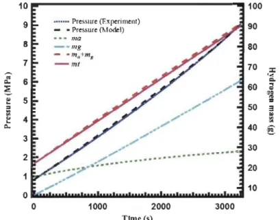
Figure 2.8: Pressure and mass evolution when 77 K hydrogen is charged into a 2.5
L cryo-sorptive MOF-5 tank ... 29
Figure 2.9: Heat source contributions and their influence on bed temperature
evolutions as 77 K hydrogen is charged at a rate of 15 SLPM into 2.5 L
cryo-sorptive tank filled with MOF-5. Arrows point toward the axis corresponding to
the data ... 30
Figure 2.10: P&ID of the test bench and the monitoring points of the tank. ... 31
Figure 2.11: Comparison between the temperatures at points Tl, T2 and T4 of
experimental validation and simulations at room temperature. An entire
chargingjdischarging cycle is shown here ...
33
Figure 2.12: Comparison between the temperatures at points Tl, T2, T3 and T6 of
experimental validation and simulations at cryogenie temperature. Only the
charging stage is shown here ...
34
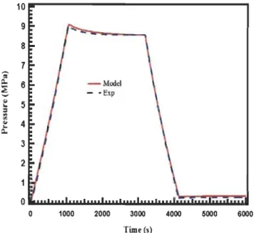
Figure 2.13: Experimental and simulation results for the pressure in the tank at
room temperature ... 35
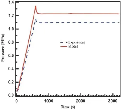
Figure 2.14: Experimental and simulation results for the pressure in the tank at
cryogenie temperature ... 35
Figure 3.1: Comparison of the experimental pressure with that obtained from the
simulation during a flowthrough run ... 45
Figure 3.2: Comparison ofthe experimental temperature with that obtained from
the simulation during a flowthrough run ...
.46
Figure 3.3: Comparison of the average bed temperatures obtained from
flowthrough simulations with those obtained when only a LN2 cooling bath was
used ...
47
Figure
3.4: The amount of hydrogen stored in the system obtained from
flowthrough simulations with those obtained when only a LN2 cooling bath was
used. The amount of hydrogen stored during flowthrough experiments are also
compared with that obtained from simulation ...
.48
Figure 3.5: Equilibrium fraction of
para
hydrogen as function oftemperature and
enthalpy of
para-ortho
hydrogen conversion ... 50
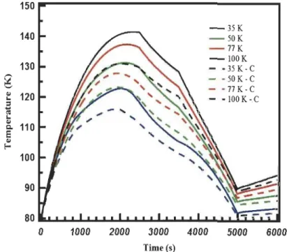
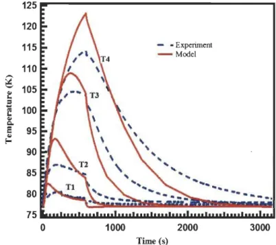
Figure 3.6: Temperature profiles at T 4 in the tank with (dashed lines) and without
(solid lines) taking into account the
para-ortho
conversion at 4 inlet temperatures .
... 53
Figure 3.7: Pressure profiles at T4 in the tank with (dashed lines) and without
(solid lines) taking into account the
ortho-para
conversion at 4 inlet temperatures .
... 53
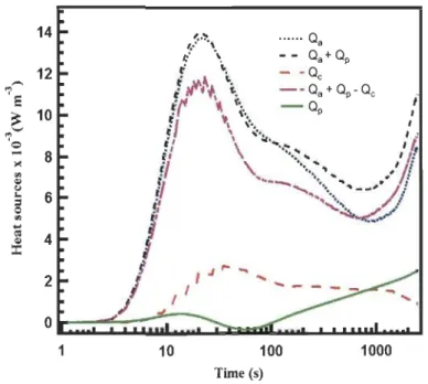
Figure 3.8: Heat sources profiles in the system at the point T4 ... 54
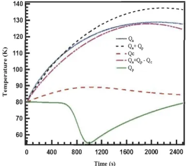
Figure 3.9: Temperature profiles at the point T4 when different heat source terms
are considered separately ... 55
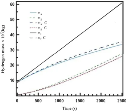
Figure 3.10: Hydrogen mass balance in the system with and without conversion .
... 56
Figure 4.1: Storage reservoir and its 2d-axisysmmetrical representation ... 60
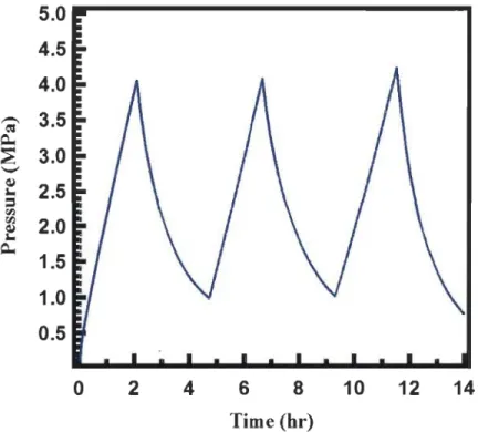
Figure 4.2: Pressure of the tank du ring the chargingjdischarging cycles ... 62
Figure 4.3: Temperature of the tank during the chargingjdischarging cycles ... 63
Figure 4.4: Pictorial representation of tank's temperature profile during the
chargingj discharging cycles ... 64
Figure 4.5: Average bed temperature, pressure and outlet temperature du ring the
whole chargingjflowthrough stage ... 65
Figure 4.6: Evolution of the temperature inside the 20 m
3bulk storage tank
containing MOF-5. (a) at the onset of charging,
(b)
after charging hydrogen at a
rate of 10000 SLPM, (c) during flowthrough for 30 hours and (d) du ring idling for
30 hours (without flowthrough) ... 66
Figure 4.7: Stored mass of hydrogen during the whole chargingjflowthrough
stage ...
.
... 68
Figure 4.8: Average temperature and pressure in the system when
para-ortho
conversion together with flowthrough cooling and flowthrough cooling alone
scenario ... 70
Figure 4
.
9: Effect of the mass flow rate on the temperature reduction during the
flowthrough stage ... 71
Figure 4.10: Hydrogen loss duringthe dormancy stage ... 73
List of Tables
Table 2.1: Volume calibration of different parts of storagejflowthrough test
bench ...
.
... 21
Table 2.2: Modified D-A model parameters ofMOF-5 ... 23
Table 2.3: Densities and porosities of MOF-5 ... 24
Table 2.4: Modified D-A model parameters ofAX-2pM ... .32
Table 2.5: Material properties ofAX-21™ ...
.
... 32
BET
BPR
BPV
CFD
DOE
D-A
D-R
EOS
LN2
MFC
MOF
NI
NIST
PT
SLPM
TMFC
TMFR
Acronyms
Brunauer-Emmett-Teller
Back Pressure Regulator
Back Pressure Valve
Computational Fluid Dynamics
Department of Energy of United States of America
Dubinin-Astakhov
Dubinin-Radushkevich
Equation of State
Liquid Nitrogen
Mass Flow Controller
Metal Organic Framework
National Instruments
National institute for Standard and Technology
Pressure Transducer
Standards Litre per Minute
Thermal Mass Flow Controller
Thermal Mass Flow Reader
Cps
}ih
h
w
k
keqks
MH2
ma
na nmaxP
Po
Tf
Q
Qp
Nomenclatures
Specifie heat capa city ofhydrogen gas, J kg-
1K
-
l
Specifie heat capa city of adsorbent, J kg-
1K
-l
Particle diameter, mm
Enthalpy, kJ kg-
1Heat transfer coefficient ofwater, W m-
ZK1
Permeability, m
ZEquivalent thermal conductivity, W m-1K
-1Thermal conductivity of adsorbent, W m-
1K1
Thermal conductivity ofhydrogen gas, W m-1K
-1Molecular mass of hydrogen, kg moP
Mass of adsorbed hydrogen, kg
Mass of gas phase hydrogen, kg
Total mas s, kg
Absolute adsorption amount/unit mass of adsorbent, mol kg-
1Limiting adsorption (per unit mass of adsorbent),
corresponding to the maximum filling of the entire volume
of adsorption space, mol kg-
1Pressure, Pa
Pseudo-saturation pressure, Pa
Fluid temperature, K
Heat source term, W m-
3Adsorption heat source, W m-
3Heat source due to pressure-volume work, W m-
3qst
Isosteric heat of adsorption,
J
mol
-
1R
Universal gas constant,
J
mol-lK-l
Sm
Mass source term, kg m-
3 S-1T
Temperature, K
U
Darcy velocity, m
S-1a
Enthalpie factor,
J
mol-
1f3
Entropie factor,
J
mol-l K-l
y
Ratio of specifie heat capacities
J1
Dynamic viscosity, Pa s
pb
Bulk density, kg m
-
3pg
Density ofhydrogen gas, kg m-
3ps
Skeleton density of adsorbent, kg m
-
3Eb
Bed porosity
Et
Total porosity
1.1 Context
Chapter 1
Introduction
Energy is a pre-requisite for economic development. Every sector of
economy, namely agriculture, industry, transport, commercial, and domestic,
needs inputs of energy. The growing consumption of energy has turned this world
increasingly dependent on fossil fuels such as coal, oil and gas. Increased use of
fossil fuels contributes to various environmental problems [1-3]. Hydrogen has
been identified as a potential energy carrier for the future mainly due to the
possibility of producing it from renewable sources and its non-polluting nature
[4-6]. However, there are many technical challenges that remain to be solved
before hydrogen can be introduced in a significant way into our energy system [7,
8]. Among them, hydrogen storage is a key challenge in developing a resilient
hydrogen economy. Compressed hydrogen storage is one of the few commercially
available hydrogen storage technologies. It is relatively simple and the filling of a
tank can be completed in a short period oftime [9]. However, low volumetric and
gravimetric densities are the major disadvantages of the compressed storage
method. Hydrogen is stored in the form of liquid hydrogen (LH2) is another
commercially available hydrogen storage technology [10, 11]. Due to its higher
density, liquid hydrogen requires much lesser volume for the same quantity of
hydrogen than in the compressed storage method. However, the high energy
consumption associated with liquefaction processes and continuous boil-off
during storage are the major disadvantages of the liquid hydrogen storage method
[12]. To overcome these storage issues, many alternative storage methods are
being extensively researched. Among the various approaches for hydrogen
storage, hydrogen storage via physisorption on porous materials has attracted
great attention due to the fast kinetics of the sorbent materials at low
temperatures and moderate pressure, large surface area, complete reversibility of
the storage process, etc. [13-15]. Among these porous materials, the mieroporous
material MOF-5 has been entieed as one of the promising materials for adsorptive
hydrogen storage due to its large surface area, high gravimetrie hydrogen capacity
at low temperature and affordable material cost [16-18]. Hydrogen molecules
interact with the MOF-5 via the weak Van der Waals force whieh results in low
isosteric heat of adsorption in the range of 4-7 kJ mol-
1at room temperature.
Because of the weakness of the gas-surface interactions, hydrogen uptake in
MOF-5 is relatively low (-1
wt
%)
at room temperature [15, 16]. Therefore, in order to
achieve the desired hydrogen uptake in MOF-5, it is necessary to use cryogenie
temperatures [19].
Even though MOF-5 can meet the storage density necessary for vehicular
hydrogen storage applications purely on the basis of its adsorption capacity, it is
not evident that any realistic hydrogen storage system built using the MOF-5 can
readily meet aIl required system performance targets [20]. This is because the
overaIl performance of a storage system depends not only on MOF-5's hydrogen
storage density but also on the storage and thermal behavior of the entire storage
system. Since thermal effects in a cryo-adsorptive storage system play a
predominant role in designing an efficient adsorption based system, proper
thermal management throughout the charging-discharging process is necessary
[21]. During the hydrogen charging process, the heat generated due to adsorption
and pressure work must be removed from the storage system to maintain the
cryogenie condition of the MOF-5 fiIled system [22]. However, the heat removal
from powdered MOF-5 filled storage system is difficult due to the po or thermal
conductivity ofpowdered MOF-5 [23,24]. To enhance the heat removal from the
MOF-5 bed, approaches such as the addition of expanded natural graphite material
to the MOF-5 and inclusion of conducting material in storage system have been
previously studied[23, 24, 25]. Either way, the net volumetrie hydrogen density of
the storage system is reduced due to the addition of non-adsorbing heat transfer
materials. Alternative heat removal methods are the implementation of the
flowthrough cooling and the charge-discharge cycles in the storage system.
Flowthrough cooling is the circulation of cold hydrogen through the adsorbent
bed, where the adsorptive heat from the bed is removed convectively by
continuous flowing of cold hydrogen gas [26]. A flowthrough system consists of a
loop of hydrogen gas through whieh the cold gas is introduced into the storage
system and any non-adsorbed hot gas is recirculated back into a refrigeration unit,
where the hot gas is cooled and reintroduced into the storage vessel. Since
hydrogen desorption from the adsorbent bed is an endothermic process,
charge-discharge cycles or adsorption-desorption cycles can be considered as a cooling
option for cooling the storage system. On the other hand, a hydrogen storage
system can experience the cooling effect if the
para
hydrogen to
ortho
hydrogen
conversion takes place in the storage system. Molecular hydrogen has two phases
of nuclear spin orientation:
para
hydrogen (nuclear spin is anti-parallel, triplet
state) and
ortho
hydrogen (nuclear spin is parallel, singlet state). At room
temperature, normal hydrogen is at thermodynamic equilibrium, whieh has 75
%
ortho
and 25
%
para
fractions. Below the room temperature, the composition of
para-ortho
fraction present in the hydrogen is defined as equilibrium hydrogen.
temperature decreases to 20
K.
The conversion of
para
to
ortho
and
ortho to para
are endothermic and exothermic reactions, respectively [27]. Currently, the
method for storage system filling uses either pre-cooled hydrogen at liquid
nitrogen temperature or cryo-compressed supercritieal hydrogen [28]. In such
cases, if the cryogenie hydrogen is not already at equilibrium
ortho-para
composition, depending upon the temperature increment owing to the heat leak
in the tank, a significant amount ofhydrogen would be lost during the storage time
due to heat release du ring the conversion. A method to avoid this storage loss is
to naturally or catalytieally convert normal hydrogen to the
para
form after the
cooling. If
para
hydrogen enters the storage tank, the temperature of the tank will
be reduced due to the endothermic
para
to
ortho
conversion. Although hydrogen
storage research focuses mainly on the vehieular storage tanks, research on the
larger bulk counterparts, whieh are used at central hydrogen production facilities,
transport terminaIs and end-use locations are gaining attention. However, unlike
the vehicular tanks, the pilot-scale design and experimentation of bulk-hydrogen
storage tank filled with MOF-S to evaluation of its multiphysies performance is
cumbersome, expensive and practieally difficult. A convenient approach is
therefore to predict such bulk tank's thermal and storage performance using a
numerieal model that couples heat and mass transfer with the adsorption kinetics.
1.2 Objective
of the thesis
The objective of the work presented in this thesis is to understand the thermal and
storage performance of a bulk (20 m
3)hydrogen storage reservoir filled with
MOF-S. In order to investigate the performance of the storage reservoir using a
multiphysies approach, initially, a general computational fluid dynamies (CFD)
obtained from the test bench equipped with a subscale-prototype (2.5 L)
cryo-adsorptive tank filled with MOF-5. The validated model is extended by applying
the flowthrough cooling to study its effects on the multiphysics performance of the
storage system. In order to compare flowthrough simulation results with bench
test results, a series of flowthrough experiments are performed. The original
validated model is then extended to study the effect of
para-ortho
conversion on
the performance of the storage system. Here, we assume that MOF-5 has enough
catalytic activities for causing rapid
para-ortho
conversion. FinaIly, the CFD model
that accounts for flowthrough cooling,
para-ortho
conversion and
charge-discharge cycle is scaled to study the performance of the bulk storage reservoir.
For aIl CFD simulations in this thesis, COMSOL Multiphysics
®
is used as a platform
to implement the model.
1.3 Structure of the thesis
The thesis is divided into three sections. Section A consists of five
chapters including introduction, three working chapters and a general summary
followed by future outlook. Context, objective and structure of the thesis are
presented in chapter
1.
Chapter 2 covers the basics of adsorption, development of
adsorptive storage system computational fluid dynamics model and model
validation using subscale-prototype storage tank filled with MOF-5. Chapter 3
deals with the results from the effect of flowthrough cooling and
para-ortho
conversion on the thermal and storage performance of the subscale-prototype
tank filled with MOF-5. Chapter 4 discusses the multiphysics performance of the
bulk hydrogen storage reservoir filled with MOF-5. The general summary of the
presented in the section B of the thesis. Section C of the thesis presents the method
ofthe model implementation in COMSOL Multiphysics® platform.
References
[1] Chiari L, Zecca A. Constraints of fossil fuels depletion on global warming
projections. Energy Policy 2011; 39:5026-5034.
[2] Ward JD, Nel WP. Comment on fossil-fuel constraints on global warming by
A. Zecca and
L.
Chiari [Energy Policy 38 (2010) 1-3]. Energy Policy 2011;
39:7464-7466.
[3] Abbasi T, Abbasi SA. Decarbonization of fossil fuels as a strategy to control
global warming. Renew sust energ rev 2011; 15:1828-1834.
[4] Dutta S. A review on production, storage ofhydrogen and its utilization as
an energy resource. J Ind Eng Chem 2014; 20:1148-1156.
[5] Nicoletti G. The hydrogen option for energy: a review of technical,
environmental and economic aspects. Int J Hydrogen Energy 1995;
20:759-765.
[6] Satyapal S, Petrovic J,
Read C, Thomas G, Ordaz G. The U.S. department of
energy's national hydrogen storage project: Progress towards meeting
hydrogen-powered vehicle requirements. Catal Today 2007; 120:246-256.
[7] Ehteshami SMM, Chan SH. The role of hydrogen and fuel cells to store
renewable energy in the future energy network-potentials and challenges.
Energy Policy 2014; 73:103-109.
[8] Mazloomi
K,
Gomes
C.
Hydrogen as an energy carrier: Prospects and
challenges. Renew sust energ rev 2012; 16:3024-3033.
[9] Zhang
J,
Fisher TS, Ramachandran PV, Gore JP, Mudawar
1.
A review ofheat
transfer issues in hydrogen storage technologies. J Heat Transfer 2005,
127: 1391-1399.
[10] Klell M, Kindermann H, Jogl C. Thermodynamics of gaseous and liquid
hydrogen storage. Proceedings international hydrogen energy congress
and exhibition IHEC; July 13-15,2007, Istanbul, Turkey.
[11] Zhou
L.
Progress and problems in hydrogen storage methods. Renew sust
energ rev 2005; 9:395-408.
[12] Jena P. Materials for hydrogen storage: past, present, and future. J Phys
Chem Lett 2011; 2:206-211.
[13] Zhao D, Yuan D, Zhou H-C. The current status ofhydrogen storage in
metal-organic frameworks, Energy Environ Sci 2008; 1:222-235.
[14] Sillar K, Hofmann A, Sauer J. Ab initio study ofhydrogen adsorption in
MOF-5. J Am Chem Soc 2009; 131: 4143-4150.
[15] Yang J. Hydrogen storage in metal organic frameworks, Thesis, Technische
Universiteit Delft; 2012, Netherlands.
[16] Serhiy Luzan. Materials for hydrogen storage and synthesis of new
materials by hydrogenation, Thesis, Umea University; 2012, Sweden.
[17] Kaye SS, Dailly A, Yaghi OM, Long JR. Impact of preparation and handling
on the hydrogen storage properties of Zn40 (1, 4-benzenedicarboxylateh
(MOF-5). J Am Chem Soc 2007; 129:14176-14177.
[18]
Li
J,
Cheng S, Zhao
Q,
Long P, Dong J. Synthesis and hydrogen-storage
behaviour of metal-organic framework MOF-5. Int J hydrogen energy
2009; 34:1377-1382.
[19] Rosi NL, Eckert J, Eddaoudi M, Vodak DT, Kim J, O'Keeffe M, Yaghi OM.
Hydrogen storage in microporous metal-organic frameworks. Science
2003; 300:1127-1129.
[20] Schmitz B, U Müller, Trukhan N, Schubert M, Férey G, Hirscher M. Heat of
adsorption for hydrogen in microporous high-surface-area materials.
Chem Phys Chem 2008; 9:2181-2184.
[21] Collins DJ, Zhou He. Hydrogen storage in metal-organic frameworks. J
Mater Chem 2007; 17:3154-3160.
[22] Hardy BJ, Anton DL. Hierarchical methodology for modeling hydrogen
storage systems. Part II: Detailed models. Int J Hydrogen energy 2009; 34:
2992-3004.
[23] Chakraborty A, Kumar S. Thermal management and desorption modeling
of a cryo-adsorbent hydrogen storage system. Int J Hydrogen Energy 2013;
38:3973-3986.
[24] Purewal J, Liu D, Sudik A, Veenstra M, Yang J, Maurer S, Müller U, Siegel DJ.
Improved hydrogen storage and thermal conductivity in high-density
MOF-5 Composites. J Phys Chem C 2012; 116:20199-20212.
[25] Liu D, Purewal
H,
Yang J, Sudik A, Maurer S, Mueller U, Ni J, Siegel DJ.
MOF-5 composites exhibiting improved thermal conductivity. Int J Hydrogen
energy 2012; 37: 6109-6117.
[26] Schuetz W, Michl F, Polifke W, Paggiaro
R.
Storage system for storing a
medium and method for loading a storage system with a storage medium
and emptying the same therefrom. US patent. US 2008/0020250 Al, Jan.
[27]
Ahluwalia RK, Hua TQ, Peng JK, Papadias D, Kumar
R.
System level analysis
of hydrogen storage options. Presentation, DOE Hydrogen Program
Review; May
9-13,2011,
Washington De, USA.
[28]
Ahluwalia RK, Peng JK. Automotive hydrogen storage system using
cryo-adsorption on activated carbon. Int J Hydrogen Energy
2009;
Chapter 2
Adsorptive hydrogen storage system model development and its
validation
This chapter discusses the basics of adsorption, the development of
computational fluid dynamics (CFD) adsorptive hydrogen storage system model
and the model validation with experimental results.
2.1 Basics of adsorption
Adsorption is the preferential adhesion of a chemical species from agas, liquid or
dissolved solid to a solid surface
.
This results in increased concentration of
chemical species close to the surface of the solid relative to the bulk of the solid
[1]. The solid surface that adsorbing the chemical species is called an adsorbent,
while the adsorbed chemical species are referred to as the adsorbate. On the basis
of the forces of attraction between adsorbent and adsorbate, adsorption is
classified as physisorption or chemisorption. Physisorption occurs mainly due to
the weak Van der Waals force of attraction between the adsorbent and the
adsorbate, while chemisorption occurs when the adsorbate is held on an
adsorbent surface by stronger chemical forces that are specifie for each adsorbent
and adsorbate.
2.1.1 Absolute and Excess adsorption
The absolute amount adsorbed, na is defined as the quantity of adsorbate
contained in the adsorption volume, V
a
the space where the density of the
adsorbate is higher than that of the bulk gas. It is given by [2]:
where,
ntotis the total amount of adsorbate introduced into the measuring system
containing the adsorbent, m
s
is the mass of adsorbent,
Po
is
the density of the bulk
gas, and
Vv. sysis the total void volume of the adsorption system (including the pore
volume of the adsorbent, the interstitial space, and any additional empty space).
The total void volume can be measured by helium probing. However, Va cannot be
measured separately. Consequently, the absolute adsorption cannot be measured
directly. However, the excess adsorption which is the additional amount of
adsorbate present in the adsorption volume can be measured directly:
ntot
V.
nex
=
ms -Pg
v,sys(2
.
2)
In terms of absolute adsorption variables, the excess adsorption is thus given by:
(2.3)
The measured excess adsorption data can be converted into absolute adsorption
by fitting the experimental excess data to an adsorption model isotherm.
Porous adsorbent
n
=
Boundary between
v
,
and V. , V •• V. + V"Figure 2.1: Difference between absolute adsorption (na) and excess adsorption
(nex)
[3].
Figure 2.1 shows the pictorial representation ofthe difference between absolute
adsorption (na) and excess adsorption (ne
x
). It shows that the absolute adsorption
is calculated by subtracting the amount of gas phase hydrogen present in the gas
phase volume from the total amount ofhydrogen present in the adsorptive storage
system whereas the excess adsorption is estimated by subtracting the amount of
gas phase hydrogen present in the adsorption volume from absolute adsorption.
2.1.2 Adsorption models
The adsorption isotherm is a curve which shows the variation of adsorption with
pressure at a given constant temperature. The adsorption model is a mathematical
representation of excess or absolute adsorption isotherms and it is required for
predicting the thermal and storage performance of the adsorptive hydrogen
storage system. A series of adsorption models such as Langmuir, Freundlich,
Brunauer-Emmett-Teller (BET), Toth, MPTA, Ono-Kondo, Dubinin-Radushkevich
(D-R), Dubinin-Astakhov (D-A), modified Dubinin-Astakhov, etc. have been
suggested and studied [4-6]. Among these, the modified Dubinin-Astakhov (D-A)
model is one of the most widely used adsorption models for adsorptive hydrogen
storage system model [7-9].
2.1.2.1 Modified Dubinin and Astakhov (D-A) model
The theory of volume filling micropores (TVFM) for analyzing the gas adsorption
isotherms on microporous materials has been proposed by
Dubinin-Radushkevich (D-R) [10]. On the basis ofTVFM theory, Dubinin and Dubinin-Radushkevich
derived a temperature invariant adsorption isotherm mode!.
It
is given by:
(2.4)
where,
naand
nmaxrepresents the amount of gas adsorbed per unit mass of
adsorbent and the limiting adsorption, respectively. The terms
A
and
Eden ote
The adsorption potential,
A,
is given by:
A
=
RTln(~)
(2.5)
where,
R
is the gas constant,
P
is the equilibrium pressure at temperature
T,
and
Po
is the saturation vapour pressure in subcritical adsorption (for supercritieal
adsorption
Po
is termed as pseudo-saturation pressure). After combined the
equations (2.4) and (2.5), the obtained linear form of the D-R equation is widely
used for linearizing the gas adsorption isotherm, and the micropore volume can
be obtained from the intercept of the D-R plot. However, sorne isotherms may give
rise to curved D-R plots due to the presence of wider micropores and broad pore
size that leads to inaccuracies in the determination of mieropore volume [11].
Dubinin-Astakhov (D-A) equation which is similar in form to the D-R equation, can
linearize the adsorption data more effectively due to an additional parameter,
k,
in the equation [11]. The isotherm is given by:
(2.6)
The parameter
k
is generally close to a small integer. The assumption of
temperature invariance in the D-R and D-A models leads to a temperature
independent characteristic free energy of adsorption,
E.However, the assumption
of temperature invariance may not be valid for very large temperature and
pressure ranges. It was found that
Ecould vary linearly with temperature [12].
Therefore, Richard et
al
proposed the following form of the characteristie free
energy of adsorption [2].
E
=
a
+
f3T
(2.7)
the terms
a
and
f3
in reference [2] are interpreted as the enthalpie and entropie
factors of the characteristie free energy.
By combining Eq. (2.4), (2.5), (2.6) and (2.7), the excess adsorption is given by:
(2.8)
The modified Dubinin-Astakhov model has been successfully adapted to describe
supercritical hydrogen adsorption in activated carbons and zeolites [2]. Recently,
this model has also been used to predict the hydrogen adsorption isotherm of
MOF-5 [7, 9]. The main disadvantage of the modified D-A model is that, at low
pressure, it does not reduce to Henry's law and at high temperature (above 200
K),
the model results negative excess adsorption data. Other than the expression
for the excess adsorption, the modified D-A model also provided an analytical
expression for the isosteric heat (q
s
t)
of adsorption [2].
(2.9)
2.2 Development of adsorptive system model for predicting the
muItiphysics performance of a hydrogen storage system
General heat and mass transfer equations together with the modified D-A model
is needed for developingthe computational fluid dynamics model of the hydrogen
adsorptive storage system.
2.2.1 Mass and momentum balance equations
The Darcy's equation together with the continuity equation is used for solving the
mass and the momentum balance equations in the adsorptive storage system
model. The Darcy's equation is based on Darcy's law, which states that the velocity
field is determined by the pressure gradient, the fluid viscosity and the structure
of the porous medium. Darcy's equation is given by:
--+ " \1
U
=
--vp
where,
ü
is the velocity of the fluid,
k
is the permeability of the porous medium,
Il
is the dynamic viscosity of the fluid and
Vp
is the pressure gradient. The combined
form of Darcy's equation and the continuity equation is given by:
(2.11)
In Eq. (2.11),
p
and
Ebare the density of the hydrogen gas flowing through the
adsorbent bed and bed porosity, respectively. The bed porosity,
Ebis the fraction
of the porous bed where hydrogen is present in the gaseous state. The bed porosity
is calculated by using the total porosity,
Etand the micro porosity,
Em;of the porous
bed [13]. In the porous bed, total porosity is the fraction of the bed where
hydrogen is present in the gasjadsorbed phases and micro porosity is the fraction
of the bed where hydrogen is present in the adsorbed phase. The following
correlations are used to deduce the total, micro and bed porosities of the
adsorbent bed in the tank.
Total porosity,
Et=
1-
Pb(2.12)
Ps
VaxMadsorbent
(2.13)
Vbed
Micro porosity,
Em;=
Bed porosity,
Eb=
Et-Em;(2.14)
where,
Pb, ps, Va, Madsorbentand
Vbedare bed density, skeleton density, adsorption
volume obtained from the modified D
-
A model, the mass of the adsorbent and the
volume of the adsorbent bed, respectively. The dynamic viscosity,
Il
of the
hydrogen gas is obtained from NIST standard reference database [14]. The
permeability,
k
of the Eq. (2.11) is determined from the diameter of the adsorbent
particles,
D
pand bed porosity,
Ebusing the relation [15].
In Eq. (2.11), Sm is the mass source term or the term which refers to the mass
generation rate per unit volume of the adsorbent that includes only the micropore
volume of the adsorbent.
S
m=
-Pb
M
H2ijt ana(2.16)
where, Pb, MH2 and
na
are the adsorbent bed density, molar mass of hydrogen gas
and absolute adsorption, respectively. The negative sign of the Sm implies that
desorption increases the amount of gaseous hydrogen. In Eq. (2.16),
na
is the
absolute adsorption obtained using the modified Dubinin-Astakhov (D-A)
adsorption model. In this model, the absolute adsorption is related to the state
variables, temperature T and pressure P using Eq. (2.16) [2].
(2.17)
where, R is the universal gas constant. The term m is the heterogeneity parameter
of the adsorbent material. The quantity,
nmaxrepresents the limiting absolute
adsorption corresponding to the limit
p~po,where po is the pseudo-saturation
pressure. The terms
a
and
f3
are enthalpy and entropie contributions to the free
energy of adsorption.
2.2.2 Energy conservation equation
To describe the energy conservation of the storage system, we use the standard
energy balance equation for hydrogen gas flowing through the adsorbent bed [7]:
(2.18)
the first and second term in the left hand side ofthe Eq. (2.18) represent enthalpy
and convection, respectively. The first and second terms of the right hand side
represent the conduction and the heat sources, respectively.
In Eq. (2.18), the equivalent volumetrie heat capa city of the adsorbent-gas system
is given by:
(2.19)
where,
pg
and
pb
are the densities of the hydrogen gas and the adsorbent material,
Cpg, Cpa
and
Cpsare specifie heat capacities of the hydrogen gas, the adsorbent-gas
mixture and the porous material, respectively. The heat capacity of the
adsorbent-gas system is written as a volumetrie average of the adsorbent-gas and the solid phases; the
solid phase includes the contribution of the adsorbed phase of hydrogen. In the
model, the specifie heat capacity of adsorbed gas is assumed to be the same as that
for the adsorbed phase. Le.,
Cpa ~Cpg.The equivalent conductivity of the
adsorbent-gas system in Eq. (2.18) is the net conductivity of the medium including that of the
adsorbent
ks and of the gas kg, weighed using the effective porosity. The equivalent
thermal conductivity is obtained using the mixing rule [16]:
(2.20)
The heat source term Q
in Eq
.
(2.18) is the sum of the contributions from the
adsorption heat Qa,
and heat produced by pressure-volume work Qp
.
The heat of
adsorption Qa,
is given by [8]:
(2.21)
where,
qstis the isosterie heat of adsorption, whieh is given by the modified D-A
model as [2]:
(2.22)
The heat generated due to pressure-volume work is given by the following
expression [8]:
where, Ur and
Uzare the components of velocity field along the radial and axial
direction.
2.3 Validation ofmodel with experimental data obtained from the
test bench using MOF-5 as an adsorbent material
A detailed description of the test bench,
the experimentation, the parameters used
for simulation, the geometry and monitoring points, the initial and boundary
conditions, and the results and discussions are presented in this section.
2.3.1 Test bench
The schematic of the bench-scale test system used to probe hydrogen charging and
flowthrough is shown in the Figure 2.2.
- Charging IiM
- Disclwging line
- Flow-through lint
,.fe al&au Flow Control*' MfR -Ibn Flow R • . , BPR • 81Ck Prtllun ReguI.tor PT-PresSUtt Tnnsduc., PR • Prn:sw. r.gulator TC • Thonnocooplo TovtntlvKuum
![Figure 3.5: Equilibrium fraction of para hydrogen as function oftemperature and enthalpy of para-ortho hydrogen conversion [17, 21]](https://thumb-eu.123doks.com/thumbv2/123doknet/14644541.735780/72.918.235.708.155.538/equilibrium-fraction-hydrogen-function-oftemperature-enthalpy-hydrogen-conversion.webp)