HAL Id: cea-02072723
https://hal-cea.archives-ouvertes.fr/cea-02072723
Submitted on 27 Mar 2019HAL is a multi-disciplinary open access archive for the deposit and dissemination of sci-entific research documents, whether they are pub-lished or not. The documents may come from teaching and research institutions in France or abroad, or from public or private research centers.
L’archive ouverte pluridisciplinaire HAL, est destinée au dépôt et à la diffusion de documents scientifiques de niveau recherche, publiés ou non, émanant des établissements d’enseignement et de recherche français ou étrangers, des laboratoires publics ou privés.
Using Shape Diversity on the Way to Structure-Function
Designs for Magnetic Micropropellers
Felix Bachmann, Klaas Bente, Agnese Codutti, Damien Faivre
To cite this version:
Felix Bachmann, Klaas Bente, Agnese Codutti, Damien Faivre. Using Shape Diversity on the Way to Structure-Function Designs for Magnetic Micropropellers. Physical Review Applied, American Physical Society, 2019, 11, pp.034039. �10.1103/PhysRevApplied.11.034039�. �cea-02072723�
1
Using Shape Diversity on the way to new Structure-Function Designs for
Magnetic Micropropellers
Felix Bachmann1, Klaas Bente1,2, Agnese Codutti1,3, Damien Faivre1,4* 1
Department of Biomaterials, Max Planck Institute of Colloids and Interfaces, Science Park Golm, 14424 Potsdam, Germany
2
Department of Nondestructive Testing, Bundesanstalt für Materialforschung und -prüfung, Unter den Eichen 87, 12205 Berlin, Germany
3
Department of Theory & Bio-Systems, Max Planck Institute of Colloids and Interfaces, Science Park Golm, 14424 Potsdam, Germany
4
CEA/CNRS/ Aix-Marseille Université, UMR7265 Institut de biosciences et biotechnologies, Laboratoire de Bioénergétique Cellulaire, 13108 Saint Paul lez Durance, France
Keywords: magnetism; microswimmers; reversal; frequency; swarm control; sorting
Abstract
Synthetic microswimmers mimicking biological movements at the microscale have been developed in recent years. Actuating helical magnetic materials with a homogeneous rotating magnetic field is one of the most widespread techniques for propulsion at the microscale, partly because the actuation strategy revolves around a simple linear relationship between the actuating field frequency and the propeller velocity. However, the full control of the swimmers’ motion has remained a challenge. Increasing the controllability of micropropellers is crucial to achieve complex actuation schemes that in turn are directly relevant for numerous applications. The simplicity of the linear relationship though limits the possibilities and flexibilities of swarm control. Using a pool of randomly-shaped magnetic microswimmers, we show that the complexity of shape can advantageously be translated into enhanced control. In particular, directional reversal of sorted micropropellers is controlled by the frequency of the actuating field. This directionality change is linked to the balance between magnetic and hydrodynamic forces. We further show an example how this behavior can experimentally lead to simple and effective sorting of individual swimmers from a group. The ability of these propellers to reverse swimming direction solely by frequency increases the control possibilities and is an example for propeller
2
designs, where the complexity needed for many applications is embedded directly in the propeller geometry rather than external factors such as actuation sequences.
I. Introduction
Microswimmers are envisioned for a multitude of applications ranging from solving environmental problems to being used for micro surgery [1-4]. Precise, versatile and non-invasive controllability is necessary to cover this broad scope of applications. These requirements are mostly matched by magnetic microswimmers. The fuel-free actuation by weak and homogeneous magnetic fields indeed allows remote controlling in many environments, the synthesis via nanofabrication makes them accessible even on a sub-micrometer scale [5-8]. In addition, the ability to functionalize their surface and the limited toxicity of the mostly iron-based propellers makes them appealing for medical applications [2,9]. Many of the current magnetic microswimmers use a helical shape with a fixed magnetic moment to rotate in an externally applied magnetic field, which enables stable propulsion. In this case, a simple linear relationship between the frequency of the actuating magnetic field and the velocity of micropropellers is used to precisely control the propeller [6,10-13]. This leaves the sign of the swimming direction of the propeller to be determined by the rotation direction of the applied magnetic field, which limits the versatility of their actuation capability: when controlling two or more geometrically identical propellers, it is not possible to let them swim in a common propulsion mode respectively in the same direction and, if needed, in opposite directions, simply because they identically react to the same rotation and / or rotation reversal of the field such that they eventually all swim always in the same direction. This does not change even by using the non-linear propeller behavior after the so called stepout frequency.
Joining and splitting of swarms of microswimmers in 3D plays however an important role for multi targeting tasks from micro-manipulation to self-organization and drug delivery. With the helical swimmers, this is only possible with complex actuation sequences [14] that have remained theoretical. Recent studies have now shown that non-linear propelling behaviors can be obtained for particular devices [15-18]. The general theory describing linear and non-linear cases depicts a change of the propeller’s axis of rotation as a function of the externally applied frequency for
3
many geometries [19]. So far, this behavior was only appreciated as a non-swimming (tumbling) and a swimming (wobbling) regime [15,17].
Here, we take advantage of a synthetic route to random-shaped micropropellers [9,20] to test new actuation schemes in this context. Screening a pool of randomly shaped micropropellers, we select those reversing their swimming direction based on the applied actuation frequency. Comparing this frequency-induced reversal with recent progresses in their theoretical description, we make an argument for expanding the degree of controllability of micropropellers. We in particular demonstrate the isolation of a single propeller from a swarm. This structure function relationship can lead to a new direction in designing magnetic micropropellers, where controllability is not embedded into actuation sequences but is already included in the geometry of the microswimmer.
II. Experimental Details
The magnetic microswimmers used here are randomly shaped microparticles that were synthesized previously [9]. Their general swimming capability was shown elsewhere [9,21]. They consist of iron(III)-nanaoparticles (20-40nm, NanoArc®, Alfa Aesar) that were connected via hydrothermal carbonization [22] to rigid structures with a magnetic moment fixed to their body [9]. Stored in a dilute suspension in deionized water, some propellers are filled into a glass capillary (0.2x2x50 mm) by capillary forces and the open ends are sealed with petroleum jelly to hinder evaporation and unwanted flows of the fluid. The capillary is fixed on an objective slide, which is, in turn, put on the stage of a custom made 3D-Helmholtz-Coil setup [23]. The capillary hangs up side down on the objective slide and is illuminated from the top by a LED-light source (either 400 nm or 635 nm, CoolLED Ltd.). Below the capillary, a 60x Plan Apochromat 1.20 WI Nikon® objective is placed in the optical path, which is led by a mirror system to high-speed cameras (Andor Zyla 5.5 sCMOS with a maximum resolution of 2560 x 2160 or an Optronis CR3000x2 with 1710 x 1696 pixels respectively). The sedimented propellers are brought to bulk fluid far away from surfaces by a rotating magnetic field 𝐵(𝜔, 𝑡) = (𝐵0sin(𝜔, 𝑡) , 𝐵0cos(𝜔, 𝑡) , 0) with the rotational angular frequency 𝜔 = 2 𝜋 𝑓. Subsequently, the axis of the rotating magnetic field is changed to be along the y-direction
4
(𝐵(𝜔, 𝑡) = (𝐵0sin(𝜔, 𝑡) , 0, 𝐵0 cos (𝜔, 𝑡))) to measure the velocity along this axis in the bulk fluid. The magnetic field strength is typically chosen to be between 1 and 3 mT and the frequency between 1 and 150 Hz depending on the characteristics observed during the measurement. Testing different frequencies (usually in 10 Hz steps) shows candidates for propellers with frequency dependent swimming direction. Such propellers are then brought in approximately the same orientation by applying a constant magnetic field along the x-direction, until the rotating field starts. The rotating magnetic field is applied for 10 s for each frequency and the propulsion of the propeller is imaged and recorded. After another constant field, the rotational frequency is increased in 1 Hz steps. The propeller velocity in dependence of the applied external frequency is determined from the propeller position along the axis of rotation. More details can be found in the supplemental material [24].
III. Results and Discussion
A. Direction reversal and correlation with propeller orientation
Randomly shaped magnetic micropropellers were observed in an inverted custom-designed optical microscope [9,23] and are actuated in water far away from surfaces by a rotating magnetic field 𝐵(𝜔, 𝑡) = [𝐵0sin(𝜔, 𝑡) , 0, 𝐵0cos(𝜔, 𝑡)]′. Some of them show a behavior we call frequency-induced reversal of swimming direction (FIRSD). In other words, the propeller swims in two opposing directions for two different field frequencies of the external actuating magnetic field, while no other parameter is changed. This stands in contrast to direction inversions used before, where the magnetic field rotation needed to be inverted to reverse the swimming direction. The velocity-frequency-relationship of propellers exhibiting FIRSD is presented in Figure 1 (A and
D) for two exemplary propellers. An inverse radon-transformation provides 3D-reconstructions
of the propeller shapes from the recorded 2D images using the projections of the rotating propellers (Figure 1 B and E, more information in SM [24], Fig. S7 and S8) [25,26]. Figure 1 C
and F show shape specific velocity landscapes that reflect all coulpling possibilities of the
respective propellers because more than one possibility can be obtained for a given shape due to the variety of different magnetic properties possible (cf. SM VI. [24]). Additionally, microscope image snapshots of the propeller configuration to the horizontal axis of rotation are put in the
5
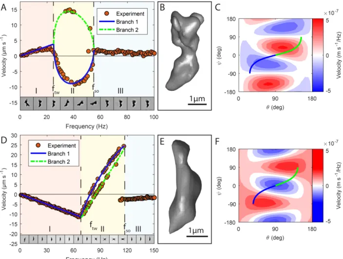
according frequency regime at the bottom. A theoretical fit (Appendix, [27]) is added to the experimental results of the frequency-dependent velocity measurements in Figure 1 A and D. Typically, the curves exhibit a linear regime at low frequencies where the propellers rotate around their short axis (tumbling, region I in Figure 1; propeller 1: f = 0 - 25 Hz; propeller 2: f = 0 - 68 Hz). At a transition frequency ftw, the behavior changes, and the propellers tilt their long axis towards the horizontal axis of rotation of the actuating field (wobbling, cf. Figure 2 A) (propeller 1: ≈ 25 Hz; propeller 2: ≈ 68 Hz). In this frequency regime (region II in Figure 1), the fit as well as the experimental data imply the existence of two solution branches (blue solid line and green dashed line). These correspond to different orientations of the propeller during its actuation in an external rotating field. First, we focus on one branch (solid blue) and will discuss the implications of the branching in the next section. The change in the axis of rotation with respect to the propeller geometries alters the rotation-translation coupling of the propellers at each frequency step. In general, this leads to a non-linear relationship between the actuating field frequency and the propeller velocity. Here, the sign of the coupling and therefore the velocity changes with frequency: both propellers slow down after ftw and eventually reverse their swimming direction (propeller 1: ≈ 27 Hz; propeller 2: ≈ 77 Hz). Due to the different orientation of the propeller towards the axis of rotation, the behavior deviates from the single linear behavior seen for other magnetic micropropellers [6,11,12,28]: while still turning in the same sense of rotation, the swimming direction reverses. Finally, the velocity breaks down at the frequency fso (propeller 1: ≈ 55 Hz; propeller 2: ≈ 117 Hz), reminiscent to what is seen for the behavior after the step out frequency of linear propellers. Here, the propellers, with their magnetic moment m fixed in their geometry cannot follow the frequency of the magnetic field rotation anymore and apparently return to a rotation around their short axis (microscope images panel A and D, asynchronous regime, region III in Figure 1). The maximum velocities (Table I) for propeller 1 for the two opposing swimming directions are v = 3 µm s-1 at f = 22 Hz and v = -9 µm s-1 at f = 41 Hz. Propeller 2 swims at v = -11 µm s-1 for f = 66 Hz and up to 24 µm s-1 for f = 117 Hz. The respective minimal and maximal dimensionless velocity U = 1000·v/(l·f) of the two propellers are also shown in Table I, where f is the frequency of the actuating external field and l the characteristic length of a propeller. The lowest and highest dimensionless speeds for propeller 1 are about 36 and -52 respectively, for propeller 2, they are 51 and -41. In summary, both propellers reorient themselves depending on the frequency and are able to effectively swim in two opposing directions by only changing the applied external frequency of the magnetic field.
6
Figure 1. Velocity-frequency-relationship. The measured velocity (red dots) dependent on the
applied frequency of the actuating magnetic field is shown in a panel A and D for propeller 1 and 2 respectively. The theoretic fit on those data points is shown in blue (solid line) and green (dashed line), which also describes the observed branching (corresponding to different propeller configuration at the respective frequencies). The 3D-reconstruction of the propellers is depicted in panel B and E. To visualize the change in propeller configuration to the horizontal axis of rotation dependent on the frequency, microscope images are shown in the measured frequency regime for one respective branch (Panel A and D on the bottom). The most left image corresponds to the orientation for a constant field in between the measurements. Both propellers show a reversal of the velocity direction in the first branch (blue), when increasing the frequency: after a linear tumble regime (I, swimming in one direction) until ftw, a non-linear wobbling regime (II happens up to the step-out frequency fso (III). During the wobbling, the long axis of the propeller starts to tilt more and more towards the horizontal axis of rotation and at a certain frequency, the propeller velocity reverses its sign – the propeller swims in the opposing direction.The respective velocity landscapes are shown in C and F as contour plots (red for positive velocities, blue for negative ones and white for zero). They reflect the velocity possibilities (in m s-1/1 Hz) of the respective propeller shape. The green and blue lines are again the branches, since the propellers are restricted to certain rotation axes for increasing frequency. The rotational similarity of propeller 2 is reflected in its velocity landscape. As a result, the branches pass similar values for increasing frequency (in contrast to propeller 1).
7
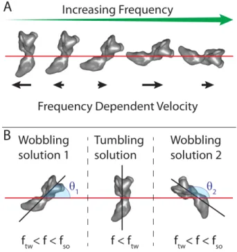
Figure 2. Frequency dependent axis of rotation (A). The orientation of a propeller towards its
axis of rotation (red horizontal line) changes with increasing frequency for some geometries to balance the magnetic and hydrodynamic torques. As a result the coupling and therefore the velocity changes with frequency, which can lead to an inversion of the propulsion direction.
Branching schematic (B). Coming from the tumbling configuration at low frequencies (middle),
two wobbling configurations are possible for higher frequencies between the transition frequency ftw and the step-out frequency fso. Here the two possibilities of Propeller 1 are depicted (cf. SM, movie S7 and S8 [24]): the first wobbling solution with an angle of 𝜃1 between the long axis of the propeller and the axis of rotation (red horizontal line) and the second solution/configuration (right side) with 𝜃2 = 180° − 𝜃1.
Table I. Propeller/Measurement characteristics.
Property Propeller 1 Propeller 2
Magnetic field B0 (mT) 2 1
Propeller length l (µm) 4.34 4.13
Propeller diameter d (µm) 1.59 1.28
Approx. magnetic momenta) m (A m²) 1.08·10-14 3.84·10-14
Magnetic Saturationb) m/msat 0.003 0.02
ftw (Hz) 25 68 fso (Hz) 55 117 vmin (µm s-1) -9 -11 vmax (µm s-1) 3 15c) 24 Umin -52 -41 Umax 36 51
8 98c) a)
Calculation from cylindrical approximation [16,29]; b) with saturation magnetization of maghemite [30]; c) Second branch values
B. Torque balance determines propeller reorientation and branching
The reorientation of the propeller with changing frequency can be explained by a balance of the acting magnetic and hydrodynamic torques [16,17] and was recently expanded to arbitrarily shaped particles [19]. When applied to our system, this leads to the following qualitative physical description: at low frequencies, the magnetic moment of the propeller is in the plane of the rotating magnetic field but lags behind with a constant angle/phase as result of the torque balance. With increasing frequency this phase is increasing too. This results in a linear regime (region I in Fig. 1, tumbling). Depending on the geometry of the propeller and the associated magnetic moment, a certain transition frequency ftw exists, where it is favorable to change the propeller orientation and to not rotate around the (hydrodynamically worse) short propeller axis anymore [17]. At this point, the magnetic moment is moved out of the magnetic field plane (non-linear regime, region II in Fig. 1, wobbling), the hydrodynamic drag is decreased by rotating around an axis with lower hydrodynamic viscous drag and the torque balance is restored. This balance (synchronous regime, region I+II in Fig. 1) can only be maintained up to a certain step-out frequency fso, where neither the phase-lag can be increased, nor the hydrodynamic drag can be decreased by reconfiguration – the propeller can no longer follow the magnetic field and the velocity breaks down (asynchronous regime, region III in Fig. 1) [17]. A detailed theoretical description of this process using the rotational mobility matrix F and coupling mobility matrix G together with the Euler angles 𝜙, θ and ψ to calculate swimming velocities can be found elsewhere [19] but is additionally shortly summarized in the SM section I. and II [24]. Fig. 1 E and F illustrate the geometrical possibilities given through F and G and how the magnetic moment orientation restricts the propellers on certain orientations and rotation axes.
Looking back at the measured data in Fig. 1 between ftw and fso, another mutual but unequally spread feature occurs, with some measuring points not following the general curve (also called branching). This branching, which was theoretically predicted [19], is not necessary for the above described frequency-induced reversal of swimming direction, but can offer further possibilities but also challenges (SM [24]). Branching is explained by the fact that two solutions are possible
9
between the two characteristic frequencies ftw and fso for the according Euler angles when applying a frequency above ftw: 𝜃1 corresponds to the blue solid line in Fig. 1 A/C and D/F and 𝜃2 = 180° − 𝜃1 to the green dashed line. These two configurations can be seen in the supplemental movie S7 [24]. Figure 2 B schematically illustrates the two possible solutions at frequencies above ftw when originating from a rotation around the short propeller axis for frequencies below ftw. The two different solutions can result in two rather different velocity responses (propeller 1) dependent on the geometry (velocity landscape in Fig. 1 C) and the associated magnetic moment (line plots in Fig. 1 C and [19]). Alternatively, propeller 2 shows a configuration where they are very similar (rather symmetric velocity landscape in Fig. 1 F). It is noteworthy that even identical velocity-responses were predicted for the two orientations ([19], point symmetric velocity landscape around tumble configuration), which would avoid non-unique velocities responses in this frequency regime. This complex behavior can be envisioned to obtain up to three different velocity responses (e.g. negative, positive, zero) for a narrow regime of the applied frequencies by providing the right initial conditions.
C. Changing propeller direction by varying the applied field strength
An additional alternative to achieve a reversal of the swimming direction is to change the strength of the applied magnetic field instead of its frequency as shown for propeller 1 at three different field strengths (0.5, 1 and 2 mT, Figure 3 A). The magnetic torque determining the propeller configuration scales linearly with magnetic moment of the propeller but also with the applied magnetic field strength (τm= B × m). Therefore the characteristic frequency-velocity curves scale with the applied magnetic field as can be seen in the inset of Figure 3, where the frequencies and the velocities of the three measurements at the different magnetic fields are normalized on the respective magnetic field – the curves fall onto each other. This can be used to reverse the swimming direction by only changing the applied magnetic field strength at a constant frequency as illustrated in the theoretical plot of the propeller velocity as function of the applied magnetic field strength and frequency (Figure 3 B). This can be achieved because the different regimes (and therefore different swimming directions) can either be reached by changing the applied frequency (horizontally) or the magnetic field strength (vertically). Exemplarily, the propeller has a velocity v ≈ -5 µm s-1
at an external frequency of 20 Hz and a field of 1 mT. At the same frequency but at 2 mT, the velocity of the same propeller is v ≈ 2.5 µm s-1.
11
Figure 3. Scaling with the magnetic field.
A: Velocity-frequency dependence of propeller 1 at three different magnetic field strength (0.5, 1
and 2 mT). Depending on the magnetic field, the propeller can swim in opposing directions for the same frequency, e.g. at f = 20 Hz for 1 mT (blue diamonds) and 2 mT (red dots). This is possible since the frequency characteristics scale with the strength of the magnetic field. In the inset the three curves are normalized on the respective field strength and therefore fall onto each other. B: Theoretical velocity as function of the applied magnetic field strength and frequency. The characteristic frequencies (ftw and fso, dashed lines) and therefore the propeller behavior scales linearly with the magnetic field strength. The three measurements at 0.5, 1 and 2 mT are depicted through the yellow, blue and red lines, respectively. Additionally, microscope images of the propeller configuration are shown to illustrate the three different regions and the two arrows indicate the respective swimming direction: the linear regime (I), the wobble regime (II) and the regime after the step-out frequency (III, not included in theory, set to 0).
D. Implication of FIRSD for swarm control
The rather basic question is why this behavior offers any benefit when comparing it to a simple reversal of the sense of rotation of the external field that would also lead to a reversal of the swimming direction. The differences between both methods can be best seen, when considering multiple microswimmers actuated by the same external field. Future applications will include tasks like isolating one specific propeller from a swarm of microswimmers. Using previous methods, this is rather complicated but possible by applying a sequence of different actuating field frequencies and directions and using e.g. the step-out behavior after the linear frequency-velocity relationship. However, this currently has mostly remained theoretical or was performed on or close to surfaces in quasi 2D [14,31,32]. A propeller with frequency-induced reversal of swimming direction allows direct targeting of this propeller at a certain frequency. Such a behavior is shown for a swarm of randomly shaped micropropellers in Figure 4 A and movie S11 [24] in 3D far away from surfaces: at a frequency of 20 Hz, the whole swarm swims in one direction (here left) until the frequency is increased to 40 Hz where all but one propellers continue swimming in the initial direction, the final one reversing its swimming direction. This proof-of-principle motivates a more sophisticated and reliable way, which is schematically depicted in Figure 4 B: four geometrically identical propellers that show FIRSD only differ in the modulus of their magnetic moment, for example swimmers prepared by 3D printing with varying amount of magnetic materials. While at low frequencies, the propeller with the smallest magnetic moment (and therefore the smallest characteristic frequencies) still swims in the same direction as the rest of the swarm, applying a frequency that is characteristic for this propeller
12
directly reverses its swimming direction, while the rest of the swarm still moves in the original direction (with slightly different velocity). The individual addressed propeller is separated from the rest. This behavior might be expanded to more propellers in the swarm so that for different propeller-specific frequencies, they reverse their swimming behavior compared to the rest of the propellers. This allows joint movement for certain frequencies, agglomeration in a certain point and splitting into groups for other frequencies. Alternatively, this method can be used to collect propellers with a certain desired behavior at selected actuation frequencies from the pool of synthesized randomly particles, sperating them locally.
Figure 4. Propeller isolation for randomly shaped propellers (A). Tracks of a group of
randomly shaped propellers. They swim all to the left for the initially applied magnetic field frequency of f1 = 20 Hz. The arrows mark the location when the frequency is increased to f2 = 40 Hz. One propeller (green track) shows a reversal of swimming direction at this frequency and swims in the opposing direction, while the rest of the swarm propellers are still in their linear regime and continue to swim to the left. This allows a joint propulsion for one frequency and an isolation of a single propeller for another as can be seen in the supplemental movie S11[24]. The according v-f-diagram is schematically shown on the left. Propeller selection schematic for
13
propellers that only differ in their magnetic moment modulus (increases from 1 to 4). At a frequency f1 all propellers swim in the same direction. At frequency f2 the propeller with the smallest magnetic moment (green, 1) has already changed its axis of rotation and has a negative velocity, while the rest of the swarm continues swimming in the original direction (positive velocity). At frequency f3 all propellers except for the one with the highest magnetic moment (blue, 4) have reversed their swimming direction. At frequency f4 all propellers swim in the opposing direction compared to f1. This offers new possibilities for controlling swarms of propellers and single propellers at the same time.
IV. Conclusion
We showed that it is possible to reverse the swimming direction of magnetic micropropellers by only changing the applied actuating frequency. This behavior offers an alternative to the traditional reversing of the actuating magnetic field and enables simple execution of previously more complicated tasks as it can help shifting the complexity of actuation to the details of the propeller geometry. In swarm control, a group of (non-identical) propellers swims together at a certain frequency. Although the common linear micropropellers are easily reversed with by a rotating field turning in the opposite direction and therefore offer great possibilities to globally manipulate swarms of microswimmers, they need a sequence of at least two magnetic field steps to join or separate subgroups of those propellers [14,32,33]. FIRSD-propellers are usually able to do those basic tasks in one step (SM section VII. [24]). For more complicated applications with longer actuation sequences and more tasks a factor of 2 can rapidly add up. Although FIRSD will not be the optimal solution to all future challenges, they offer new avenues to master them. Recently, there have been other microswimmer systems enabling direction reversal. Gomez-Solano et al. reported on thermally induced direction and motility change of self-propelled colloids, mimicking the run-and-reverse behavior of some bacteria [34]. However, the dependency on the surrounding fuel and the activation through laser light makes in-vivo applications hard to realize. Khalil et al. produced two tailed-microbots that showed frequency dependent back and forth movement through flagellar propulsion [35]. These microbots are still several hundreds of micrometer and might face micromechanical problems when scaling them down, similar to the theoretically proposed equivalent for joint helices [36]. An interesting system was presented by Garci Torres et al. with frequency induced reversal based on an interplay of magnetic, hydrodynamic and gravitational interactions [37]. However, their system is a self-assembled swimmer that requires nearby surfaces to break symmetry and is thereofore rather complemental than alternative to our propellers swimming far away from surfaces. Our
14
proposed system uses penetrable remote control through weak homogenous magnetic fields together with the intrinsic rich interplay between a fixed geometry and magnetism in magnetic micropropellers. This enables a defined change of axis of rotation in dependence of the applied external frequency or magnetic field strength and can therefore be envisioned as an alternative to the common field reversal in some applications. However, there will always be a trade-off between a certain functionality or application a propeller can be used for and its effective propulsion. This is the case for the here reported propellers: more efficient, constant stable propulsion over a large frequency regime is traded with the ability to control the sign of the swimming direction and the propeller speed by applying the right frequency beyond the usual linear relationship. This feature is currently under-used but can add to the controllability of the propellers apart from the currently considered options (field orientation/shape deformation/soft magnetic materials). Especially with the current urgent need of automatization for the control of microrobots [3,38], this offers a simple and continuous method to change the swimming behavior drastically by only changing one parameter (frequency) in the system. Path and time optimization algorithms can benefit from micropropellers with frequency-induced reversal of swimming direction, since it facilitates addressing single propellers in a swarm of microswimmers. In this context, it is to keep in mind that with actual practical applications, the requirements on the magnetic fields will increase and set limits to available frequencies and field strengths that could drastically differ from the conditions currently used in labs (e.g. by magnetic coil systems big enough for human limbs). FIRSD and in general non-linear propellers can therefore be of some advantage for certain challenges. Another challenging task in this regard is to implement a feedback control/visualization of the microswimmers to make automatization possible in the first place. There have been studies using the fields of magnetic resonance imaging (MRI) to power magnetic microswimmers [39,40]. And with magnetic particle imaging (MPI) [41] another visualization method is on the horizon that might facilitate this for medical applications. In those systems, the magnetic fields possibilities are limited in the sense that they are optimized for the imaging rather than the propulsion. It will therefore be necessary to provide the needed complexity and flexibility for navigation in biological environments by introducing different actuation modes like reversing the swimming direction and changing speed rather by the design of the magnetic micropropellers than by the limited accessible magnetic fields.
15
For expanding the range of possible new applications, it is crucial to acquire a more substantial knowledge about arbitrary shaped propellers to be able to systematically design micropropellers for specific tasks. Analytically, a direct link between shape and swimming behavior is missing, but with more experimental studies and simulations, this connection will become clearer (a few remarks on this are in SM VI. [24]). Additionally to the two examples shown here, more propellers with frequency-induced reversal of propeller direction were found during the measurements (SM movies [24]). While it might not be a surprise that random shaped micropropellers show deviations from the linear frequency-velocity relationship, those are often very small and negligible [21]. With this, we can already formulate some basic requirements for FIRSD (cf. SM [24]): (i) the magnetic moment of such propellers has to be parallel and perpendicular to the principle axis of rotation [19]; (ii) the coupling matrix has to have non-vanishing elements of opposite sign for at least two directions which are determined by the frequency dependend axis of rotations. However, looking at more non-linear cases and their mobility matrices might enable us to draw a clearer map, which geometric features give contributions to such coupling and therefore to the reversal in swimming direction.
Recent progress in material synthesis, especially in 3D printing, already provides tools to potentially realize the production of experimentally found propeller geometries and therefore access to those new actuation strategies, without relying on filtering more randomly shaped propellers. Additionally, 3D printing may provide the possibility to structurally search the geometrical requirements for FIRSD. However, not every detail of the observed behavior is currently fully understood. In particular, the Euler angles, which describe the frequency-dependent orientation of the propellers, become time frequency-dependent after fso and even though some suggestions have been proposed [17] to describe the interactions in this regime, it cannot explain the here measured experimental data. The option for future applications to be able to design propellers with distinct geometry that actively makes use of the changing axis of rotation or even the observed branching, by actively determining it, can be beneficial. They could either swim in opposing direction, use the non-linear regime to increase or decrease the effective coupling and therefore speed up or slow down the velocity, or simply overcome certain setup limitations in regard of the magnetic field. This will therefore help to facilitate and speed up envisioned tasks and is a step towards user and application-friendly micropropellers.
16
Apendix
A. Estimation of rotational drag coefficients and magnetic moment
The magnitude of the magnetic moment and its angle towards the long axis of the chosen propeller coordinate system can be estimated with the experimentally measured characteristic frequencies ftw and fso(or the according angular velocities ωtw and ωso) from the relevant drag or friction coefficients [16,17]. Therefore an approximation of the propellers of either a cylinder [16,29] or an ellipsoid [17] is needed, to analytically calculate the rotational drag coefficients. We chose to follow Ortega and de la Torre [29] and Ghosh et al. [16] since the cylindrical approximation seemed rather fitting for our propeller shapes (cf. microscope images and the 3D-reconstruction of the exemplary propellers in Fig. 1). The according drag coefficients for rotations around the short (γs) and long (γl) cylinder axis are as follows:
𝛾𝑆 = 𝜋𝜋𝑙 3 3 (ln 𝑝+𝐶𝑟⊥ ) (1) 𝛾𝑙 =𝜋𝜋𝑙 3(1+𝐶𝑟∥) 0.96 𝑝2 (2) with 𝐶𝑟⊥ = −0.662 +0.917𝑝 −0.100𝑝2 (3) 𝐶𝑟∥ =0.677𝑝 −0.183𝑝2 (4) where η = 8.9·10-4
Pa s is the viscosity of water at 25°C and p = l/d the ratio of the cylinder length l and its diameter d. Then the component of the magnetic moment fixed in the propeller along the long axis of the cylindrical approximation is
𝑚∥ =𝜔𝑡𝑡𝐵0𝛾𝑠 (5)
and along the short axis
𝑚⊥ = 𝛾𝑙/𝐵0� 𝜔𝑠𝑠2 − 𝜔𝑡𝑡2 . (6)
17 𝑚 = �𝑚∥ 2 + 𝑚
⊥ 2 (7)
Φ = arctan 𝑚⊥/𝑚∥ (8)
Details on the reference frame of the cylindrical approximations and the azimuthal angle can be found in the supplemental material ([24], Figure S5). The values for the magnitude of the calculated magnetic moments of propeller 1 and 2 based on this approximation are shown in Table S1, together with the quantities required for the calculation (magnetic field strength B0, characteristic propeller length l and diameter d, characteristic frequencies ftw and fso). The magnetic moment can additionally be compared with the magnetization saturation of the respective propeller assuming the same volume of ordered material ([24], Table S1). To calculate the relative magnetization of the propellers the saturation magnetization of maghemite [30] is needed (Ms = 380 kA m-1):
𝑚𝑠𝑠𝑡 = 𝜋𝜋 𝑑
2
4 𝑀𝑠. (9)
The relatively low magnetization values of 0.3 % and 2 % for propeller 1 and propeller 2 respectively can be explained since the random shaped propellers consist of unordered maghemite nanoparticles.
B. Theoretical framework for arbitrarily shaped magnetic micropropellers
Below the step-out frequency fso, it is possible to describe the orientation of a propeller by the Euler angles 𝜙, θ and ψ [42]. Their dependency on the frequency is determined by the propeller shape and the orientation of the magnetic moment with respect to this shape. The propeller geometry determines the mobility matrices: the rotational mobility matrix F, the translational mobility matrix ε and the coupling mobility matrix G [19]. A so called center of hydrodynamic mobility can be found for every propeller geometry, where F is diagonal and G is symmetric, [19] similar to the center of hydrodynamic reaction described by Happel and Brenner [43]. Together with the magnetic moment (magnitude, orientation) and the magnetic field strength, F determines the Euler angles and therefore the orientation of the propeller, depending on the applied frequency (cf. next paragraph on mobility matrices and lit. [19]), whereas G couples the
18
forced rotation to an effective translation of the propeller. According to Morozov et al., [19] the resulting velocity 𝑣 = 𝑣(𝐼)+ 𝑣(𝐼𝐼) along the axis of rotation can be written as the sum of the velocities coming from the diagonal and off-diagonal elements of G, 𝑣𝐼 and 𝑣𝐼𝐼 respectively: 𝑣(𝐼)
𝜔𝑙 = 𝐶ℎ1sin2𝜓 sin2𝜃 + 𝐶ℎ2cos2𝜓 sin2𝜃 + 𝐶ℎ3cos2𝜃 (10) 𝑣(𝐼𝐼)
𝜔𝑙 = 𝐶ℎ12sin 2𝜓 sin2𝜃 + 𝐶ℎ13sin 𝜓 𝑠𝑠𝑠 𝜃 + 𝐶ℎ23cos 𝜓 sin 2𝜃 (11) with the length l of the propeller, the frequency of the external field 𝜔 = 2𝜋𝑓 and 𝐶ℎ𝑖 = 𝐺𝑖𝑖/𝐹𝑖 and 𝐶ℎ𝑖𝑖 = 1
2𝑙 (𝐺𝑖𝑖/𝐹𝑖 + 𝐺𝑖𝑖/𝐹𝑖) when 𝑠 ≠ 𝑗.
The advantage of the cylindrical approximation is that it also simplifies the calculation of the frequency-dependent Euler angles (see next paragraph). The transverse rotational isotropy of the propellers [19] basically implies a similar magnitude of the rotational mobility coefficients in the non-elongated directions, as it is given for a approximated cylinder: 𝐹1 = 𝐹2 < 𝐹3. Therefore, using this approximation leaves only the elements of the mobility coupling matrix 𝐺𝑖𝑖 as unknown parameters (cf. Eq.(10-11)), which are used as fitting parameters on the experimental data. However, the more ideal way would be to have access to the geometrical parameters G and
F (e.g. through simulation of the reconstructed shape) and only use the magnetic moment and the
characteristic frequencies as fit parameters, which is work in progress. The fits were done with the NonlinearModelFit function of Mathematica [27].
Mobility matrices and Euler angles
The mobility matrices, determined by the geometry of the propeller, relate forces (𝓕) and torques (L) with velocities (U) and roation rates (𝜴) for the low Reynolds number:
�𝑈𝛺� = �𝐺𝜀† 𝐺𝐹� �ℱ𝜋� (12) They have the following form in the center of hydrodynamic mobility [19], which axes were chosen here to be along the long and short axis of the approximated cylinder:
19 �𝐹0 𝐹1 02 00 0 0 𝐹3 � (13) �𝐺𝐺1112 𝐺𝐺1222 𝐺𝐺1323 𝐺13 𝐺23 𝐺33 � (14)
With the Euler angles 𝜙, θ and ψ describing the orientation of the propeller in the lab system (cf. Fig. S3.) [42] and the two angles α and Φ that describe the orientation of the magnetic moment in the propeller, the transverse rotational isotropy solution is accessible for the cylindrical approximation. F⊥ = F1 = F2 < F3 = F∥ then applies for the three diagonal elements of F, with F1 and F2 being the inverse rotational drag coefficients (γs-1) of the cylinder rotating around the short axis and F3 the inverse rotational drag coefficient around the long axis (γl-1), respectively. In this case, the solution for the frequency dependent Euler angles can be given for the two synchronous regimes: tumbling solution before ωtw [19]:
𝜃 =𝜋2, 𝜓 = −𝛼, 𝜙� = −Φ + arccos 𝜔� (15) wobbling solution between ωtw and ωso [19]:
𝜃1 = arcsincos Φ𝜔� , 𝜓1 = −𝛼 − arcsincos 𝜃sin Φ𝐹1𝜔� 𝐹∥⊥ , 𝜙�1 = 0 (16) 𝜃2 = 𝜋 − 𝜃1, 𝜓2 = −2 𝛼 − 𝜓1 , 𝜙�2 = 0 (17) with 𝜔� = 𝜔
𝑚 𝐵0𝐹⊥ and 𝜙 = 𝜙� − 𝜔𝑡.
The second values for the wobbling solution correspond to the second branch solution. Together with Eqn. (10) and (11), the frequency dependent velocity for the transverse rotational isotropic approximations is accessible [19].
Acknowledgements
The authors thank Prof. Stefan Klumpp for discussion, Dr. Mathieu Bennet and Klaus Bienert for technical advice and support.
20
Funding: This work was funded by Deutsche Forschungsgemeinschaft within the Priority
Program 1726 on microswimmers (grant No. FA 835/7-1) and the Max-Planck Gesellschaft. A.C. is supported by the IMPRS on Multiscale Biosystems.
21
References
[1] J. Liu, S. Z. Qiao, Q. H. Hu, and G. Q. Lu, Magnetic nanocomposites with mesoporous structures: synthesis and applications, Small 7, 425 (2011).
[2] M. Colombo, S. Carregal-Romero, M. F. Casula, L. Gutierrez, M. P. Morales, I. B. Bohm, J. T. Heverhagen, D. Prosperi, and W. J. Parak, Biological applications of magnetic nanoparticles, Chem. Soc. Rev. 41, 4306 (2012).
[3] F. Qiu and B. J. Nelson, Magnetic Helical Micro-and Nanorobots: Toward Their Biomedical Applications, Engineering 1, 21 (2015).
[4] C. Bechinger, R. Di Leonardo, H. Lowen, C. Reichhardt, G. Volpe, and G. Volpe, Active Particles in Complex and Crowded Environments, Rev. Mod. Phys. 88, 045006 (2016).
[5] A. Ghosh and P. Fischer, Controlled propulsion of artificial magnetic nanostructured propellers, Nano Lett 9, 2243 (2009).
[6] S. Tottori, L. Zhang, F. Qiu, K. K. Krawczyk, A. Franco-Obregon, and B. J. Nelson, Magnetic helical micromachines: fabrication, controlled swimming, and cargo transport, Adv. Mater. 24, 811 (2012). [7] D. Schamel, A. G. Mark, J. G. Gibbs, C. Miksch, K. I. Morozov, A. M. Leshansky, and P. Fischer, Nanopropellers and their actuation in complex viscoelastic media, ACS Nano 8, 8794 (2014).
[8] T. Li, J. Li, H. Zhang, X. Chang, W. Song, Y. Hu, G. Shao, E. Sandraz, G. Zhang, L. Li, and J. Wang, Magnetically Propelled Fish-Like Nanoswimmers, Small 12, 6098 (2016).
[9] P. J. Vach, N. Brun, M. Bennet, L. Bertinetti, M. Widdrat, J. Baumgartner, S. Klumpp, P. Fratzl, and D. Faivre, Selecting for function: solution synthesis of magnetic nanopropellers, Nano Lett. 13, 5373 (2013).
[10] P. Fischer and A. Ghosh, Magnetically actuated propulsion at low Reynolds numbers: towards nanoscale control, Nanoscale 3, 557 (2011).
[11] W. Gao, X. Feng, A. Pei, C. R. Kane, R. Tam, C. Hennessy, and J. Wang, Bioinspired helical microswimmers based on vascular plants, Nano Lett. 14, 305 (2014).
[12] J. Li, S. Sattayasamitsathit, R. Dong, W. Gao, R. Tam, X. Feng, S. Ai, and J. Wang, Template electrosynthesis of tailored-made helical nanoswimmers, Nanoscale 6, 9415 (2014).
[13] H. C. Fu, M. Jabbarzadeh, and F. Meshkati, Magnetization directions and geometries of helical microswimmers for linear velocity-frequency response, Phys. Rev. E: Stat., Nonlinear, Soft Matter Phys. 91, 043011 (2015).
[14] P. J. Vach, S. Klumpp, and D. Faivre, Steering magnetic micropropellers along independent trajectories, J. Phys. D: Appl. Phys. 49, 065003 (2016).
[15] A. Ghosh, D. Paria, H. J. Singh, P. L. Venugopalan, and A. Ghosh, Dynamical configurations and bistability of helical nanostructures under external torque, Phys. Rev. E: Stat., Nonlinear, Soft Matter Phys. 86, 031401 (2012).
[16] A. Ghosh, P. Mandal, S. Karmakar, and A. Ghosh, Analytical theory and stability analysis of an elongated nanoscale object under external torque, Phys. Chem. Chem. Phys. 15, 10817 (2013).
[17] K. I. Morozov and A. M. Leshansky, The chiral magnetic nanomotors, Nanoscale 6, 1580 (2014). [18] U. K. Cheang, F. Meshkati, D. Kim, M. J. Kim, and H. C. Fu, Minimal geometric requirements for micropropulsion via magnetic rotation, Phys. Rev. E: Stat., Nonlinear, Soft Matter Phys. 90, 033007 (2014).
[19] K. I. Morozov, Y. Mirzae, O. Kenneth, and A. M. Leshansky, Dynamics of arbitrary shaped propellers driven by a rotating magnetic field, Phys. Rev. Fluids 2, 044202 (2017).
[20] Z. B. Zhang, H. F. Duan, S. H. Li, and Y. J. Lin, Assembly of Magnetic Nanospheres into One-Dimensional Nanostructured Carbon Hybrid Materials, Langmuir 26, 6676 (2010).
[21] P. J. Vach, P. Fratzl, S. Klumpp, and D. Faivre, Fast Magnetic Micropropellers with Random Shapes, Nano Lett. 15, 7064 (2015).
22
[22] Z. Zhang, H. Duan, S. Li, and Y. Lin, Assembly of magnetic nanospheres into one-dimensional nanostructured carbon hybrid materials, Langmuir 26, 6676 (2010).
[23] M. Bennet, A. McCarthy, D. Fix, M. R. Edwards, F. Repp, P. Vach, J. W. Dunlop, M. Sitti, G. S. Buller, S. Klumpp, and D. Faivre, Influence of magnetic fields on magneto-aerotaxis, PLoS One 9, e101150 (2014).
[24] See Supplemental Material at [...] for measurement details, further discussion of implications and more examples of FIRSD-propellers including video material showing this behavior.
[25] A. C. Kak and M. Slaney, Principles of computerized tomographic imaging (IEEE Press, New York, 1988).
[26] J. Radon, Berichte über die Verhandlungen der Königlich-Sächsischen Gesellschaft der Wissenschaften zu Leipzig, Mathematisch-Physische Klasse, 262 (1917).
[27] Mathematica, (Wolfram Research, Inc.) (2017).
[28] L. Zhang, J. J. Abbott, L. Dong, K. E. Peyer, B. E. Kratochvil, H. Zhang, C. Bergeles, and B. J. Nelson, Characterizing the swimming properties of artificial bacterial flagella, Nano Lett. 9, 3663 (2009).
[29] A. Ortega and J. G. de la Torre, Hydrodynamic properties of rodlike and disklike particles in dilute solution, J. Chem. Phys. 119, 9914 (2003).
[30] C. J. Serna and M. P. Morales, Maghemite (γ-Fe2O3): A Versatile Magnetic Colloidal Material (Springer US, Boston, MA, 2004), Surface and Colloid Science.
[31] A. W. Mahoney, N. D. Nelson, K. E. Peyer, B. J. Nelson, and J. J. Abbott, Behavior of rotating magnetic microrobots above the step-out frequency with application to control of multi-microrobot systems, Appl. Phys. Lett. 104, 144101 (2014).
[32] X. Wang, C. Hu, L. Schurz, C. De Marco, X. Chen, S. Pané, and B. J. Nelson, Surface-Chemistry-Mediated Control of Individual Magnetic Helical Microswimmers in a Swarm, ACS Nano (2018). [33] T. A. Howell, B. Osting, and J. J. Abbott, Sorting Rotating Micromachines by Variations in Their Magnetic Properties, Phys. Rev. Appl. 9, 054021 (2018).
[34] J. R. Gomez-Solano, S. Samin, C. Lozano, P. Ruedas-Batuecas, R. van Roij, and C. Bechinger, Tuning the motility and directionality of self-propelled colloids, Sci. Rep. 7, 14891 (2017).
[35] I. S. M. Khalil, A. F. Tabak, Y. Hamed, M. E. Mitwally, M. Tawakol, A. Klingner, and M. Sitti, Swimming Back and Forth Using Planar Flagellar Propulsion at Low Reynolds Numbers, Adv. Sci. 5, 1700461 (2017).
[36] P. Katsamba and E. Lauga, Micro-Tug-of-War: A Selective Control Mechanism for Magnetic Swimmers, Phys. Rev. Appl. 5, 064019 (2016).
[37] J. García-Torres, C. Calero, F. Sagués, I. Pagonabarraga, and P. Tierno, Magnetically tunable bidirectional locomotion of a self-assembled nanorod-sphere propeller, Nat. Commun. 9, 1663 (2018). [38] M. Medina-Sanchez and O. G. Schmidt, Medical microbots need better imaging and control, Nature 545, 406 (2017).
[39] G. Kosa, P. Jakab, G. Szekely, and N. Hata, MRI driven magnetic microswimmers, Biomed. Microdevices 14, 165 (2012).
[40] N. Kumar, V. Verma, and L. Behera, Magnetic navigation and tracking of multiple ferromagnetic microrobots inside an arterial phantom setup for MRI guided drug therapy, Biocybern. Biomed. Eng. 37, 347 (2017).
[41] K. Bente, M. Weber, M. Graeser, T. F. Sattel, M. Erbe, and T. M. Buzug, Electronic field free line rotation and relaxation deconvolution in magnetic particle imaging, IEEE Trans. Med. Imaging 34, 644 (2015).
[42] L. D. a. L. Landau, E. M. , Mechanik (Akademie-Verlag GmbH, Berlin, 1970), Vol. 7.
[43] J. Happel and H. Brenner, Low Reynolds number hydrodynamics : with special applications to
particulate media (M. Nijhoff ; Distributed by Kluwer Boston, The Hague ; Boston Hingham, MA, USA,