HAL Id: tel-01419298
https://tel.archives-ouvertes.fr/tel-01419298v2
Submitted on 26 Jan 2017HAL is a multi-disciplinary open access
archive for the deposit and dissemination of sci-entific research documents, whether they are pub-lished or not. The documents may come from teaching and research institutions in France or abroad, or from public or private research centers.
L’archive ouverte pluridisciplinaire HAL, est destinée au dépôt et à la diffusion de documents scientifiques de niveau recherche, publiés ou non, émanant des établissements d’enseignement et de recherche français ou étrangers, des laboratoires publics ou privés.
components : formalisation and tools
Oleksandra Kulankhina
To cite this version:
Oleksandra Kulankhina. A framework for rigorous development of distributed components : formal-isation and tools. Other [cs.OH]. Université Côte d’Azur, 2016. English. �NNT : 2016AZUR4077�. �tel-01419298v2�
UNIVERSIT´E DE NICE-SOPHIA ANTIPOLIS ´
Ecole Doctorale STIC
Sciences et Technologies de l’Information et de la Communication
TH`
ESE
pour l’obtention du titre de
Docteur en Sciences
Mention Informatique
pr´esent´ee et soutenue par
Oleksandra Kulankhina
A framework for rigorous
development of distributed components:
formalisation and tools
Th`ese dirig´ee par Eric Madelaine
Soutenue le 14 Octobre 2016
Jury
Rapporteurs Radu Mateescu Inria Grenoble - Rhˆone-Alpes
Frantiˇsek Pl´aˇsil Charles University, Prague
Examinateurs Fr´ed´eric Mallet Universit´e Nice Sophia Antipolis
Ludovic Henrio CNRS
Simon Bliudze EPFL, Lausanne
Directeur de th`ese Eric Madelaine Inria Sophia Antipolis
iii
R´esum´e
Dans cette th`ese, nous proposons une approche rigoureuse pour la conception et le d´eveloppement de syst`emes `a base de composants hi´erarchiques distribu´es. L’id´ee de base du travail pr´esent´e est de combiner les techniques de conception de logiciels dirig´ees par les mod`eles, bien connues des programmeurs, avec des m´ethodes de v´erification formelles puissantes, capables d’assurer les propri´et´es fonctionnelles d’un syst`eme distribu´e et de d´etecter les erreurs d`es le stade de la conception.
Tout d’abord, nous introduisons un formalisme graphique bas´e sur UML pour l’architecture et le comportement des composants hi´erarchiques de mod´elisation. Deuxi`emement, nous sp´ecifions formellement un ensemble de contraintes qui assurent la correction de la composition des composants, en mettant l’accent sur la s´eparation entre les aspects fonctionnels et non-fonctionnels. Troisi`emement, nous expliquons comment nos mod`eles graphiques peuvent ˆetre traduits automatiquement dans le formalisme d’entr´ee d’un model-checker. Nous nous concentrons ensuite sur le codage des fonctionnalit´es avanc´ees de composants distribu´es, comme communications de 1 vers N, la reconfiguration et les communications asynchrones bas´ees sur les appel de proc´edures distants.
Enfin, nous mettons en œuvre cette approche dans une plateforme int´egr´ee orient´e mod`ele qui comprend un ensemble d’´editeurs graphiques, un module de validation de la d´ecision correcte de l’architecture statique, un module traduisant le mod`ele conceptuel dans une entr´ee pour la plateforme de v´erification CADP, et enfin un g´en´erateur de code ex´ecutable
Abstract
In this thesis we introduce an approach for rigorous design and development of distributed hierarchical component-based systems. The core idea of the presented work is to combine the well-known among the programmers techniques for model-driven software design and the powerful formal verification methods able to ensure the functional properties of a distributed system and to detect errors at the early design stage.
First, we introduce a UML-based graphical formalism for modelling architecture and behaviour of hierarchical components. Second, we formally specify a set of con-straints that ensure the correct components composition with a focus on separation between the functional and non-functional aspects. Third, we explain how the graph-ical models can be automatgraph-ically translated into an input for a model-checker. For this aim, we rely on a formally specified intermediate structure encoding the se-mantics of components behaviour as a network of synchronised parametrised label transition systems. We focus here on encoding the advanced features of distributed components such as one-to-many communications, reconfiguration, and asynchronous communications based on request-reply.
Finally, we implement the approach in an integrated model-driven environment which comprises a set of graphical editors, an architecture static correctness validation plug-in, a plug-in translating the conceptual model into an input for a verification toolsuite CADP, and a generator of the implementation code.
Acknowledgements
First of all, I would like to thank my advisors Eric Madelaine and Ludovic Henrio for giving me the opportunity to do a PhD, for all the discussions that we had, for all their ideas, and for the time they spent on working with me. I would like to thank Radu Mateescu and Frantisek Plasil who kindly agreed to review this dissertation. I would like to thank Frederic Mallet, Simon Bliudze, and Rabea Ameur-Boulifa for doing the honour to be the members of the jury for my defence.
I would like to thank Justine Rochas for the enormous support and help, for keeping the great atmosphere in our office, for all those hundreds of things she has done for me. I cannot imagine this PhD and my life in France without her.
I would like to thank Fabrice Huet for the constant support, for a lot of advice he gave me in any kind of situation, and for the help. I would like to thank Sophie, Christel, Vincenzo, Fabien, Francoise, and all the members of Oasis and Scale team. I would like to thank Iyad who welcomed me in the team. I would like to thank Alexandra for being so kind to me and for introducing me to the project. Also, I would like to thank all the engineers and interns with whom I worked on the VerCors platform. I would like to thank Julien De Antoni for his help with the implementation. I would like to thank the professors of Kharkiv National University of V.N. Karazin, and especially Iryna Zaretska for giving me a solid background in mathematics and informatics which allowed me to become a PhD Candidate.
I would like to thank my boyfriend Hlib Mykhailenko for the enormous support and his ability to find in any situation the right words that encouraged me. I would like to thank Yurii Guznienkov for introducing me to the world of computer science, it is 100% thanks to him that I have chosen the field about which I am so passionate. I would like to thank all other members of my family and my friends for the support. Last but not least, I would like to thank my mother Iryna Didorchuk. Neither this dissertation no other achievements in my life would be possible without her love and support.
Table of Contents
List of Figures xi
List of Listings xiii
List of Tables xv
1 Introduction 1
1.1 Motivation and objectives . . . 1
1.2 Contribution . . . 7
1.3 Outline . . . 10
2 Context 13 2.1 The Grid Component Model . . . 14
2.1.1 GCM overview . . . 14
2.1.2 GCM/ADL . . . 17
2.1.3 GCM/ProActive . . . 18
2.2 Parameterised networks of synchronised automata . . . 24
2.2.1 Term algebra and notations . . . 24
2.2.2 The pNets model . . . 25
2.2.3 Observation and flow of information . . . 27
2.2.4 Adequacy of pNets for modelling GCM components . . . 28
2.3 CADP . . . 29
2.4 The Fiacre specification language . . . 32
2.5 Model-Driven Engineering . . . 33
2.5.1 Unified Modelling Language . . . 34
2.5.2 Eclipse Modeling Framework . . . 35
2.5.3 Obeo Designer . . . 36
2.6 VerCors . . . 37
3 An overview of the VerCors platform 41
3.1 The core functionalities of VerCors . . . 41
3.2 Diagrams for architecture and behaviour specification . . . 44
3.2.1 An illustrative example . . . 44
3.2.2 Architecture specification . . . 45
3.2.3 Behaviour specification . . . 48
3.3 The architecture of VerCors . . . 51
3.4 Discussion . . . 55
4 Well-formed component architecture 59 4.1 Formalisation of component structure . . . 60
4.2 Auxiliary functions . . . 61
4.3 Interceptors . . . 63
4.4 Well-formed component architecture . . . 65
4.4.1 Core . . . 65
4.4.2 Non-functional aspects . . . 68
4.4.3 Collective communications . . . 70
4.4.4 Additional rules . . . 71
4.5 Properties . . . 71
4.6 Architecture static analysis in VerCors . . . 74
4.7 Discussion and Related work . . . 74
5 Verification and execution of distributed components 79 5.1 From application design to pNets . . . 80
5.1.1 Semantics of primitive components . . . 81
5.1.2 Semantics of composite components . . . 92
5.1.3 Implementation . . . 100
5.2 From pNets to CADP . . . 108
5.2.1 Preparing the input: generating Fiacre, EXP and auxiliary scripts108 5.2.2 Model-checking with CADP . . . 112
5.3 Code generation and execution . . . 115
5.3.1 ADL generation . . . 116
5.3.2 Java generation . . . 118
5.3.3 Code execution . . . 123
5.4 Discussion . . . 124
5.4.1 On the verification . . . 124
TABLE OF CONTENTS ix
6 Advanced features 127
6.1 Non-functional components and interceptors . . . 129
6.1.1 From application design to pNets . . . 129
6.1.2 Implementing pNet generation and integration with CADP . . 134
6.1.3 Code generation . . . 134
6.2 Component attributes and attribute controllers . . . 135
6.2.1 Graphical specification . . . 136
6.2.2 From application design to pNets . . . 137
6.2.3 Implementing pNet generation and integration with CADP . . 138
6.2.4 Code generation . . . 139
6.3 Reconfigurable multicast interfaces . . . 140
6.3.1 Graphical specification . . . 141
6.3.2 From application design to pNets . . . 142
6.3.3 Implementing pNet generation and integration with CADP . . 155
6.3.4 Code generation . . . 157
6.4 Reconfiguring multicasts from NF components . . . 157
6.4.1 Graphical specification . . . 157
6.4.2 From application design to pNets . . . 158
6.4.3 Implementing pNet generation and integration with CADP . . 158
6.4.4 Code generation . . . 159 6.5 Examples . . . 161 6.5.1 Composite pattern . . . 161 6.5.2 Springoo . . . 171 6.6 Discussion . . . 173 7 Related work 177 7.1 The SOFA 2 project . . . 178
7.2 The BIP Component Framework . . . 181
7.3 Rebeca formal modelling language and development tools . . . 183
7.4 ABS . . . 188
7.5 Other frameworks . . . 191
7.5.1 Component models and tools . . . 192
7.5.2 Verification platforms . . . 196
7.6 Summary . . . 200
7.6.1 On the verification tools . . . 200
8 Conclusion 203
8.1 Summary . . . 203
8.2 Perspectives . . . 206
8.2.1 Modelling and analysis of parameterised architectures . . . 206
8.2.2 Modelling and analysis of multi-threaded components . . . 207
8.2.3 Modelling and analysis of reconfigurable systems . . . 208
8.2.4 Extending the pNet generator . . . 210
8.2.5 Properties specification and visualising the results of model-checking . . . 211
8.2.6 Static analysis and type-checking of state machines . . . 211
8.2.7 Other ideas of the future work . . . 213
A Extended Abstract in French 215 A.1 Introduction . . . 215
A.2 R´esum´e des d´eveloppements . . . 221
List of Figures
2.1 A GCM application . . . 15
2.2 Request-reply by futures . . . 19
2.3 Request treatment by GCM/ProActive components . . . 20
2.4 UML class diagram . . . 35
2.5 UML state machine diagram . . . 35
2.6 EMF example . . . 36
3.1 VerCors workflow . . . 42
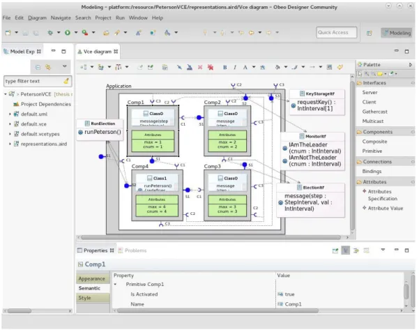
3.2 Screenshot of VerCors . . . 43
3.3 VerCors component diagram . . . 46
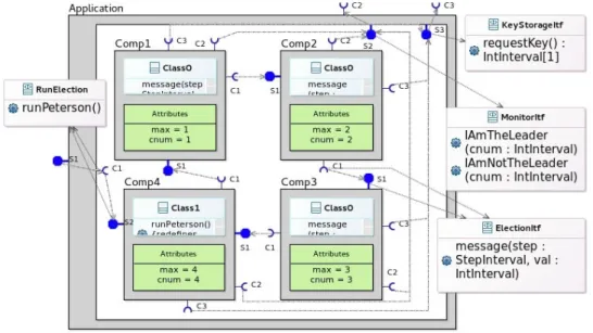
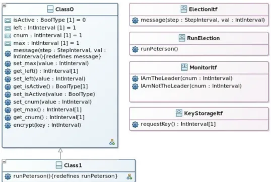
3.4 A component diagram of Peterson’s leader election use-case example . 48 3.5 VerCors class diagram . . . 49
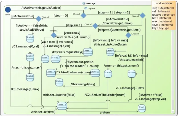
3.6 State machine diagram . . . 51
3.7 Scenario state machine . . . 51
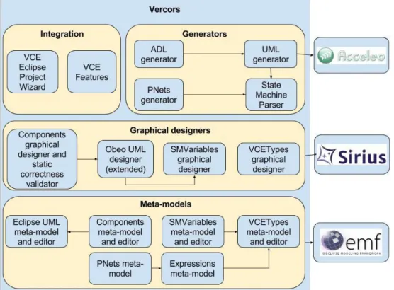
3.8 Architecture of VerCors . . . 52
4.1 Internal interfaces of a membrane . . . 63
4.2 An input chain of interceptors . . . 64
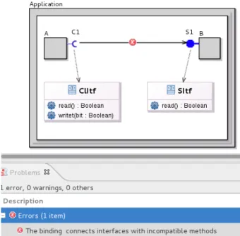
4.3 Examples of architecture constraint violations . . . 73
4.4 Architecture static correctness validation in VerCors . . . 75
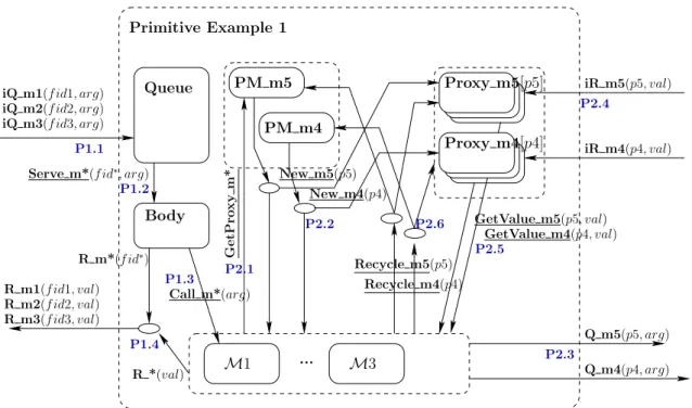
5.1 An example of a primitive component . . . 82
5.2 pNet for the PrimExample component from Figure 5.1 . . . 83
5.3 Graphical representation of the behaviour of the Body . . . 88
5.4 pLTSs for the Future Proxies and Proxy Managers . . . 89
5.5 A state machine and its translation to a pLTS . . . 91
5.6 An example of a composite component . . . 93
5.7 pNet for the composite component from Figure 5.6 . . . 94
5.8 Auxiliary processes proxy and delegate of composite components . . . 96
5.9 pNets meta-model (simplified) . . . 102
5.10 Construction of a pNet of a primitive component . . . 105
5.11 Construction of a pNet of a composite component . . . 107
5.12 Fiacre code of a body . . . 109
5.13 The workflow of implementation code generation . . . 116
5.14 A primitive with an attached UML class . . . 121
5.15 A simple state machine . . . 122
5.16 Code execution . . . 123
6.1 Bindings in a membrane . . . 130
6.2 pNet of a component with a componentised membrane . . . 131
6.3 Graphical specification of a component attribute . . . 136
6.4 An attribute controller pLTS . . . 137
6.5 A primitive component with a multicast Interface . . . 141
6.6 A composite component with multicast internal and external interfaces 141 6.7 A Group Manager . . . 143
6.8 A Group Proxy for a method of a primitive component . . . 144
6.9 pNet model for Figure 6.5 . . . 144
6.10 Dynamic Connector for a Multicast Interface . . . 145
6.11 The Proxy of a multicast interface inside a composite component . . 149
6.12 pNets for the Composite component with multicast internal and ex-ternal interfaces . . . 150
6.13 A multicast of a sub-component sends an external request . . . 154
6.14 A Group Manager for a void method . . . 155
6.15 Modelling binding reconfiguration . . . 158
6.16 VerCors model of the composite pattern . . . 163
6.17 The class diagram of the composite pattern . . . 164
6.18 addSubcomp method . . . 165
6.19 addAnyUnbound method . . . 166
6.20 Scenario for the composite pattern application . . . 167
6.21 Springoo application modelled in VerCors . . . 172
7.1 The BIP design flow [2] . . . 181
List of Listings
2.1 ADL example . . . 18
2.2 A Java class of a GCM/ProActive primitive . . . 22
2.3 A GCM/ProActive component construction and access . . . 23
2.4 An example of synchronization vectors in .exp . . . 30
2.5 A Fiacre process . . . 33
5.1 An example of SVL script . . . 111
5.2 An example of a JAXB-based class . . . 116
5.3 An XML file generated by JAXB . . . 116
5.4 An Acceleo template translating VerCors record type into a Java class 118 5.5 Java code of a record type generated by VerCors . . . 119
5.6 Generated Java code of a primitive component . . . 120
5.7 Generated Java code of a state machine . . . 122
6.1 Generated ADL file of a composite with a componentised membrane . 135 6.2 A Java class implementing the behaviour of a primitive component with an attribute . . . 139
6.3 An ADL specification of a component attribute . . . 139
6.4 An ADL attribute which stores reconfigurable interfaces . . . 160
6.5 Java code of a component-controller . . . 160
List of Tables
4.1 The formalization of GCM architecture . . . 61
4.2 Auxiliary functions . . . 62
4.3 Interceptor predicates . . . 66
4.4 Core predicates . . . 66
4.5 Non-functional predicates . . . 68
5.2 Server and client-side synchronisation vectors for primitive components 85 5.3 Server and client-side synchronisation vectors of a pNet of a composite component . . . 97
5.4 Binding synchronisation vectors of a pNet of a composite component 98 5.5 Behaviour graph files (all with Queue size of 3) . . . 112
6.1 Attribute controller synchronisation vectors for primitive components 138 6.2 Synchronisation vectors for multicast client interfaces in primitive com-ponents . . . 147
6.3 Synchronisation vectors for multicast interfaces in composite components151 6.4 Binding synchronisation vectors for multicast interface . . . 153
7.1 Verification tools . . . 201
Chapter 1
Introduction
Contents
1.1 Motivation and objectives . . . 1 1.2 Contribution . . . 7 1.3 Outline . . . 10
1.1
Motivation and objectives
In recent years the amount of data to be processed has grown exponentially, present-ing new challenges to the software developers and scientists. It is often too large to be processed on a single machine. Distributed computing is the approach able to support the efficiency of large applications operating on big data. According to it, a program can be split into several interacting parts which are executed on differ-ent computational nodes. Programming such systems is a difficult task because the developer has to ensure not only the correctness of the behaviour of each individual module but also the correctness and consistency of their composition. The collabora-tion of several processes distributed over multiple machines and the synchronisacollabora-tion between them make the computational logic more complex. In this thesis we target checking the correctness of the computational logic of distributed applications.
Programming distributed components
A popular approach for the development of large-scale distributed applications is the component-oriented programming where a software system is split into separate modules (components) with well-defined interfaces which they use for interacting with each other. The approach enforces a clear design of the applications and provides
a solid basis for safe and modular development of complex systems. There exists a variety of component models [1, 2, 3] defining how an application should be designed, implemented, and deployed. They often use different vocabularies but in general, all of them rely the notions of components, interfaces (sometimes called ports), and
bindings (sometimes called connectors). A component can be seen as a block of a
software which provides some functionality. Components use interfaces as the com-munication points to expose their services and to access the services of each other. The bindings are used to establish the communications between the interfaces. One of the advantages of the component-oriented approach is the re-usability of components: when the developer writes a new program, he can re-use some existing components as he knows statically their provided and required functionalities. In addition to the flat composition, some models allow for the development of hierarchical systems, i.e. a component can ”wrap” other components. In this case, the former is called a parent component or a container, and the latter are its sub-components. Such an approach allows the programmer to hide the complexity of the internal implementation of a part of the system.
Even with the help of the component-oriented programming, the development of large-scale distributed applications is challenging for three main reasons. First, such software systems often rely on asynchronous requests. This means that when a component sends a request to another component, the sender does not have to block its execution waiting for the reply. As a result, two components can execute their services in parallel. This increases the efficiency of the application because serving requests in parallel can be much faster than the sequential processing and because the computational resources of the sender do not stay idle while waiting for the result of a remote method invocation. On the other hand, the asynchrony makes the development of distributed systems more complicated. The reason is that the behaviour of such components is not easy to predict at the programming stage as it is impossible to know when exactly the result of a remote computation will arrive and when it can be used.
Another challenge is presented by the evolution of a distributed system at run-time: in order to adapt to the current task or to the changes in the environment, an application often needs to be reconfigured during its execution. This may include, for instance, adding or removing components depending on the system workload. The programmer has to take care of all possible configurations of a software application and to make sure that for each of them the system will behave correctly. Manag-ing a reconfigurable system becomes even more complex in the case of hierarchical applications because the changes applied to a parent component can often affect its
1.1. MOTIVATION AND OBJECTIVES 3
content.
Finally, when programming a distributed system, it is not always easy to keep separated the functional and non-functional aspects while allowing them to commu-nicate. The former is responsible for the business logic of an application: it defines how the system behaves within the given problem domain. The latter controls the application: it measures the necessary performance metrics that are often based on the functional behaviour, plans and executes the reconfiguration. It takes care of the security aspect and the other aspects not related to the application logic. The non-functional part should not depend on the concrete system domain: whenever the software is overloaded, a new computational node should be added no matter whether it processes bank transfers, multiplies matrices, or renders a game graphics. Implementing separately the functional and non-functional parts is important for the safety and re-usability of the software components; it allows for clear definition of the objective of each part. The fact that components have well-defined provided and required interfaces, makes programming systems with strong separation of concerns easier. Moreover, sometimes the separation of concerns is enforced by a component model: some component models define functional and non-functional components and interfaces. The issue is that the two different parts of an application are often influenced by each other and often have to interact with each other, and the developer has to program these communicating parts so that they are still clearly separated.
We have defined a set of challenges that the developer of a distributed application has to face. We can see that there is a need to help the programmer to address them by providing techniques and tools which can assist in the design, analysis, and implementation of distributed system.
The Grid Component Model
Among all the existing component models, we focus on the Grid Component Model (GCM) [4] because its has the following features.
First, it allows for specifying distributed hierarchical components: at the leaves of hierarchy it has so-called primitive components which encapsulate some business code and represent the units of distribution. Then components are assembled hierarchically using compote components.
Second, the reference implementation of GCM provided by the GCM/ProAc-tive [5] middleware allows for programming loosely-coupled components that com-municate only via asynchronous requests with futures. More precisely, whenever a component sends a remote request, it creates a future object which is a placeholder for the reply. As opposed to the synchronous communications, the sender continues
its execution as long as it does not require the result of the remote method invoca-tion. When the result is needed, the sender either uses the value that was received by the future object, or waits till it is computed. Such communications are still asyn-chronous in the sense that the requester does not get blocked immediately after a remote method call, but they are much easier to control than the fully asynchronous message-passing. The communications based on futures increase the level of par-allelism as the sender can continue its execution while its remote request is being processed by another component. The absence of the shared memory makes compo-nents loosely-coupled: each component has its own local memory and thus only it is responsible for its own state and execution. This makes the model well-adapted to the distributed setting. Moreover, the usage of futures is transparent in GCM/ProActive: the programmer does not need to use any specific instructions for manipulating the futures.
The third advantage of GCM is its reconfiguration capabilities. A GCM component can be added or removed, started or stopped, and the bindings between components can be modified at run-time.
Another strong point of GCM is that it enforces separation of concerns: it de-fines the notions of functional and functional interfaces and functional and non-functional components which can have hierarchical structure. In addition, GCM provides techniques for modelling not only one-to-one but also one-to-many and
many-to-one communication styles which are widely used in the distributed systems.
Model-driven software engineering
A number of techniques which leverage the documentation, the development, and the maintainance of the large complex software are provided by the model-driven-engineering [6] approach which has become a de-facto standard for the development of industrial projects. In particular, it allows the programmer to design a model of the future application before writing its code, and thus, to plan in advance the structure and the behaviour of each component involved in the system. There exist dozens of textual and graphical notations developed in the industry and academia for the specification of the application design from various viewpoints. One of the most popular graphical languages for obejct and component-oriented systems is the Unified Modelling Language (UML) [7]. It allows for designing a software application as a set of diagrams that describe its architecture, behaviour, the interactions with the user, etc. The diagrams can be used not only for documenting the project but also as an input for the code generation. Indeed, there exist a number of tools [8, 9, 10] which partially translate a software model into executable code so that the programmer
1.1. MOTIVATION AND OBJECTIVES 5
does not need to write it from scratch. In addition, the diagrams can be statically analysed to check the absence of errors that could occur in the implementation code. The earlier an error is detected, the lower the cost of its correction. Model-driven engineering became popular in the industry also because it facilitates the maintenance of large applications. Whenever a new functionality has to be added, instead of modifying directly the implementation code, the developer can, first, introduce it in the design of the application in order to see its impact on the rest of the system.
Formal methods
A set of powerful techniques for the specification and analysis of complex software is based on formal methods. They allow one to model a system as a composition of mathematical entities and to prove certain properties on it. There exist a number of approaches [11] that differ in the underlying mathematical model, in the level of automation (some techniques are fully automatic, the others require guidance from the user), and in the addressed aspects of the input model (e.g. the timed behaviour, the safe composition of components, the interactions between concurrent processes). One technique for fully automatic and exhaustive analysis of a system behaviour is provided by model-checking. It relies on building a model of an application behaviour and on exploring its state-space in order to verify the formula which models the desired property of the input model. It can be, for instance, the reachability of a particular behaviour, or the absence of a deadlock. One of the advantages of model-checking is that it performs the exhaustive analysis of the input model which allows identifying the erroneous ”rare” scenarios that are not always covered by the software tests. The success of the approach is highlighted by its application to the large-scale projects developed by the leading modern companies and institutes such as for instance, the web-services of Amazon [12], the spacecraft controllers of NASA [13], and the flight control systems of Airbus [14].
However, model-checking can be only applied to an abstraction of the real system, encoded in a finite state manner. Such an abstraction can be obtained by analysis of the source code, but this can be costly. We prefer to associate the formal methods with the model-driven engineering approach: starting from a high-level model of an application, we can generate an abstract state-space for model-checking and some executable code. If needed, the generated code can be refined to get the final detailed implementation.
Formal methods allow one to detect a huge variety of errors in a software system at the design stage but their use in the industry is still very low. There are two key reasons for that. First, the application of such techniques can be enormously costly:
for instance, sometimes the generated state-space of a model-checked system is so huge that it is just impossible to verify it exhaustively. To address this challenge, the formal method community is working on the techniques for the state-space reduction such as partial order reduction [15], symmetry reduction [16], etc. Another reason why the formal methods are not widely used by the software engineers is the complexity of their practical usage. Mastering formal methods often requires significant background in mathematics and professional trainings. This second issue is addressed in this dissertation.
Objectives and positioning
This work aims at including systematic verification of behavioural properties in the industrial development process of component-based distributed applications. For this purpose we want to provide the developers of distributed component-based systems with a set of model-driven tools supporting rigorous design and implementation of safe applications. Our tools should guide the user through all crucial phases of component software development: from application design specification to verification of the modelled architecture and of the properties of its behaviour as well as automated code generation. More precisely, we want to:
• design a user-friendly language for the specification of hierarchical asynchronous component-based systems with reconfiguration capabilities;
• help the developers to ensure formally that the application design is statically correct and that the functional components of the modelled system are properly separated from the non-functional ones;
• develop an approach to automatically translate the user-defined specification into an input for a powerful model-checker in order to verify the properties of the modelled application;
• develop an approach to automatically translate the designed application into executable code;
• integrate all these techniques into a single framework for modelling, verification, and code generation for distributed component-based systems.
GCM features a complex programming model, and includes many advanced mech-anisms. Its operational semantics has been well-defined and formalised in previous works of the Oasis team [17], and the middleware implementation respects the model
1.2. CONTRIBUTION 7
and the semantics. However, we need a behavioural semantics (not the classical operational one) in order to allow for model-checking temporal properties. The chal-lenge here is to define this semantics in a way that respects closely the semantics of GCM/ProActive components and the middleware implementation, ensuring that the properties proven by the model-checker will be respected by the generated code.
In this thesis we target modelling and verification of distributed hierarchical component-based systems with strong separation between functional and non-functional concerns, reconfiguration capabilities, and communications based on futures. The originality of this work lies in the combination of all these features. In fact, there ex-ist a number of component models supported by development platforms that feature some of these elements. For instance, the BIP [2] component model allows specifi-cation of hierarchical asynchronous systems but does not provide the reconfiguration capabilities. The components of Rebeca [18] are asynchronous and highly dynamical but not hierarchical. The components of SOFA 2 [1] provide all the targeted fea-tures except that the non-functional part of a component can be only flat and the future-based communications are not supported. We present a deeper overview and comparison of the component models and tools related to the work presented in this thesis in Chapter 7.
1.2
Contribution
Overall, this work aims at integrating in a single framework techniques for modelling, analysis, and generation of hierarchical distributed component-based systems with asynchronous communications and reconfiguration capabilities. We would like to provide software developers with a single platform where one can model a distributed application in a user-friendly and easy-to-learn graphical language, analyse the con-ceptual model by applying powerful formal verification techniques, and generate the implementation code. We try to automatise as much as possible the analysis of con-ceptual models and code construction because we would like our framework to be used by non-experts in formal methods. We describe below the main contributions of this thesis.
Graphical specification language. We introduce a graphical language for the specification of the architecture and behaviour of component-based distributed sys-tems. The language allows expressing complex hierarchical structures comprising both business logic components (functional components) and components responsi-ble for the control and management of an application (non-functional components).
At the same time, the specifications of the two aspects are graphically separated from each other. The notations of our language extensively reuse UML elements [7] which are well-known among programmers. This makes the graphical formalism user-friendly and easy-to-learn. Several formalisms for GCM components have already been discussed in [19, 20], but none of them has been properly integrated in a soft-ware platform. Based on the previous works, in this thesis we present the first version of the specification approach for coherent and complete definition of GCM compo-nent architecture and behaviour. It integrates a domain-specific language designed for GCM components with the UML meta-model.
Formalisation of component architecture and static correctness rules. We provide a formal model for component architectures including a flexible set of con-structs for the definition of the non-functional part of an application which has never been formalised before. The business logic and control parts of a modelled system are strongly separated. Based on the architecture formalisation, we define a number of predicates insuring the static correctness of the component composition. After validation of these rules, we guarantee that the application possesses a number of properties which are necessary prerequisite for the correct execution and the recon-figurability of the system. Those properties include uniqueness of naming, separation of concerns, and communication determinacy. The properties will be also crucial during the analysis phase and the executable code generation.
Generation of behavioural models. We formalise a set of semantic rules for the transformation of the designed conceptual models into a semantic formalism allowing us to specify the details of the application behaviour and communications between components. The behavioural models are generated in terms of parameterised net-works of synchronised automata [21]. They encode future-based communications, hierarchical components, some aspects of architecture reconfiguration, and one-to-many communications. We also show how the generated structures can be automat-ically transformed into an input for a model-checker (we use the model-checker of CADP [22]) in order to verify the requirements of the designed application expressed as logical properties. Prior to this work, the approach presented in this thesis has been partially manually tested on several use-cases [23, 24]. However, this is the first work where the fully automatic translation of the graphical models into an input for a model checker is implemented as a software. The fully automatised process has also been tested on several use-case examples, and some of them are included in this dissertation.
1.2. CONTRIBUTION 9
Generation of executable code. Once the conceptual model has been proven statically correct, and its functional properties have been model-checked, we generate the executable code of the designed application. The produced code includes an XML-based file encoding the system architecture and a set of Java classes implementing the behaviour of the components. This way, we are able to run distributed applications that are proven safe. In this thesis we will explain how the generation process is organised and demonstrate several experiments of running an application produced by our framework.
Integration of graphical designer, model-checker, and execution platform. Finally, we implement and integrate the front-end graphical designer with a model-checker, and an execution middleware in a single model-driven Eclipse-based frame-work called VerCors. Using the front-end editor, the user can design the conceptual model of his application in our graphical specification language. Then, he can check that the defined architecture is statically correct with respect to the properties we formalised. Next, VerCors fully automatically generates a behavioural model of the designed application and transforms it into an input for a model-checker. As we will show in this thesis, the model-checker can verify a number of properties on the pro-duced structure. This includes both generic properties (e.g. absence of deadlocks) and application-specific properties (e.g. reachability of a particular system state, in-evitability, etc). This work does not focus on the assistance to property specification but we provide a number of examples of properties verified for our use-case models. Finally, the platform automatically produces the implementation code of the designed system which can be executed in a distributed environment1.
The work presented in this thesis is included in the following publications2:
• Ludovic Henrio, Oleksandra Kulankhina, Dongqian Liu, Eric Madelaine; ”Ver-ifying the correct composition of distributed components: Formalisation and Tool” FOCLASA, Sep 2014, Rome, Italy. The paper presents the formalisation of component architecture and static correctness properties.
• Tatiana Aubonnet, Ludovic Henrio, Soumia Kessal, Oleksandra Kulankhina, Fr´ed´eric Lemoine, Eric Madelaine, Cristian Ruz, No¨emie Simoni; ”Management
1
I encoded most of the functionalities of the VerCors platform; I coordinated the work of the students and engineers who helped me with several specific tasks; Regarding the re-used code, I integrated an existing UML editor into the front-end of VerCors; I integrated and enhanced a part of a generator of the executable code (about 40%) from the previous versions of the platform.
2
I am the main author of the publications at FOCLASA’14 and FASE’16. All the authors have equal contribution to the paper in the JISA journal. Regarding the paper submitted to the JLamp journal, I contributed to the correction and refinement of the presented formalisation, I implemented the software constructing the behavioural models according to the formalised rules.
of service composition based on self-controlled components”; Journal of Internet Services and Applications, Springer, 2015, 6 (15), pp.17. In this paper we use the VerCors platform in order to model and generate a service-oriented distributed application.
• Ludovic Henrio, Oleksandra Kulankhina, Siqi Li, Eric Madelaine; ”Integrated environment for verifying and running distributed components”; Fundamental Approaches to Software Engineering (FASE), Apr 2016, Eindhoven, Nether-lands; Springer, Lecture Notes in Computer Science, 9633, pp.66-83, 2016, Fun-damental Approaches to Software Engineering. The paper provides a general overview of the graphical formalism, behaviour generation, and executable code generation processes presented in this thesis.
• Rab´ea Ameur-Boulifa, Ludovic Henrio, Oleksandra Kulankhina, Eric Made-laine, Alexandra Savu; ”Behavioural Semantics for Asynchronous Components” (submitted to JLamp). The paper introduces detailed formalisation of the gen-eration of the behavioural models for GCM components.
1.3
Outline
The thesis is organised as follows:
Chapter 2 presents the technical background this work is based on. We describe the main component model we rely on: GCM (Grid Component Model) with its reference implementation in the GCM/ProActive middleware. We introduce the for-malism which we use for encoding component behaviour and the verification platform which we use for checking. Then, we introduce the basic notions of model-driven engineering and the tools we used for the implementation of the VerCors platform. Finally, we make a short overview of the history of VerCors and discuss what are the contributions of this thesis with respect to the previous versions of the platform.
Chapter 3 makes an overview of the version of VerCors implemented in this the-sis. We discuss its core functionalities from the user point of view, the graphical formalisms of the front-end designer, and the implementation architecture.
Chapter 4 presents the formalisation of component architecture and static cor-rectness predicates. We introduce the notion of component well-formedness and a set
1.3. OUTLINE 11
of properties insured by the validation of the predicates. We also explain how the static correctness check was implemented in VerCors. Finally, we discuss applicability of the provided architecture formalisation and predicates to the component models other than GCM, and their relation to the similar previous studies.
Chapter 5 describes the core contribution of this thesis: the semantic rules defining the construction of the behavioural models and the generation of the implementation code. We start by explaining the transformation of the specification of GCM-based architecture and behaviour conceptual models into an intermediate structure encod-ing system behaviour at a low lever (in terms of networks of parameterised automata). Then, we discuss how the generation process is implemented in VerCors, and how the constructed structures are transformed into an input for the model-checker of CADP. We also present the generation of the executable code of an application designed and verified in VerCors.
Chapter 6 extends the graphical formalism, the generation of the behavioural mod-els and of the executable code with the constructs necessary for modelling, verify-ing, and running component-based systems with advanced features. They include the non-functional components, attribute controllers, and reconfigurable one-to-many communications.
Chapter 7 presents the related works. We discuss the state-of-the-art frameworks for modelling and verification of distributed component-based systems, and we posi-tion our work with respect to the other studies. Then, we make an overview of several verification platforms and we explain why we chose the model-checker of CADP for our work.
Chapter 2
Context
Contents
2.1 The Grid Component Model . . . 14 2.1.1 GCM overview . . . 14 2.1.2 GCM/ADL . . . 17 2.1.3 GCM/ProActive . . . 18 2.2 Parameterised networks of synchronised automata . . . 24 2.2.1 Term algebra and notations . . . 24 2.2.2 The pNets model . . . 25 2.2.3 Observation and flow of information . . . 27 2.2.4 Adequacy of pNets for modelling GCM components . . . . 28 2.3 CADP . . . 29 2.4 The Fiacre specification language . . . 32 2.5 Model-Driven Engineering . . . 33 2.5.1 Unified Modelling Language . . . 34 2.5.2 Eclipse Modeling Framework . . . 35 2.5.3 Obeo Designer . . . 36 2.6 VerCors . . . 37
This chapter discusses the background required for reading this thesis. We start by an overview of the component model this work relies on and its reference imple-mentation. Second, we present an intermediate formalism that we use in order to encode the components behaviour at low level. Then, we introduce the verification
toolbox that we apply to model-check the functional properties of the component-based systems. In order to apply the model-checker we rely on an intermediate text language for the behaviour specification; the language is also discussed in this chap-ter. Next, we introduce the model-driven engineering paradigm which will be used in this thesis for tools implementation. Finally, we make a short overview of the history of the VerCors platform and compare this work to its previous versions.
2.1
The Grid Component Model
The approach presented in this work relies on the Grid Component Model (GCM). GCM was designed by the CoreGrid European network of Excellence [4] as an ex-tension of the Fractal model [25] dedicated to distributed systems, including a set of control capabilities. The framework targets the design, implementation, execution, and deployment of hierarchical reconfigurable large-scale component-based applica-tions. In this section, first, we provide an overview of GCM. Then, we describe an XML-based language for the GCM architecture specification. Finally, we introduce the ProActive middleware providing an implementation of GCM components based on Active Objects.
2.1.1
GCM overview
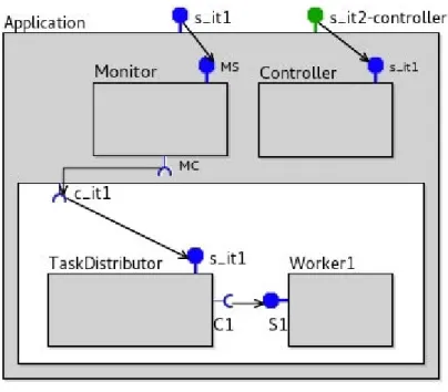
A GCM-based application consists of components, interfaces and bindings. We de-scribe each of the elements below and illustrate them in Figure 2.1. We do not explain the graphical notations here as they will be presented in details in Section 3.2.
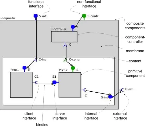
Hierarchical components. There exist two types of components in GCM depend-ing on the level of observation: primitive and composite components, we will call them ”primitives” and ”composites” correspondingly. A composite encompasses inner com-ponents which are called sub-comcom-ponents. A composite (Application in Figure 2.1) is separated into two parts: a membrane (the grey part) containing all the subcompo-nents dealing with the application management and control, and a content (the white part) which comprises the subcomponents implementing the business logic. Another component type - primitive (TaskDistributor, Worker1 in Figure 2.1) - could be seen as a black-box view on a component that encapsulates the implementation code and provides some functionality. Each primitive also has a componentised membrane responsible for control and management. A primitive can comprise attributes of prim-itive type that will be accessible from outside of the component. Each component is characterised by a name and a set of interfaces.
2.1. THE GRID COMPONENT MODEL 15
Figure 2.1 – A GCM application
Interfaces. The GCM interfaces are the communication points for the components. The communication between components is performed in the form of method invo-cation. An interface able to invoke methods and to receive the invocation results is called a client interface (e.g. C1), and interfaces that accept method invocations and send back the results are called server interfaces (e.g. S1). The interfaces that call or serve methods implementing the business logic are called functional while the ones dealing with the application control are called non-functional. The interfaces that communicate are connected by bindings (the black arrow from C1 to S1). An interface accessible from outside of a component is said to be external. An internal interface is reachable only from inside of a component.
Collective communications. In order to facilitate parallel programming, GCM defines the cardinality of an interface which can be singleton, multicast or gathercast. A singleton is the simplest interface used for one-to-one communications. A client singleton can be connected to only one target interface at each time in order to ensure the deterministic behaviour. However, a singleton server interface can be bound to several client interfaces, but a request from each client is processed separately. A
multicast provides an abstraction mechanism for the one-to-N communications. It is
a client interface that transforms a single method invocation into several requests and sends them to multiple target interfaces at the same time. If the method is supposed to return a result, the replies from the target components are collected in a single
structure and given back to the caller. An abstraction for N-to-one communication is provided by the gathercast interfaces. A gathercast is a server interface that can receive calls from several clients at the same time, the calls are assembled in a single request that is processed by the gathercast interface owner.
The separation of concerns. The functional part of a GCM application can be separated from the control part thanks to the separation of a composite component into a membrane and a content and to the usage of functional and non-functional interfaces. This separation ensures, as much as possible, the independence of the business code from the management code.
The functional aspect. The GCM was design to support wide range of non-functional capabilities which can be implemented thanks to the three core elements: predefined controllers, non-functional components, and reconfiguration mechanisms. The GCM specification describes a set of predefined entities used for an application management including:
• A Lifecycle controller is included in every component and serves to stop and start a component.
• A Attribute controller is used to configure the values of the component at-tributes.
• A Binding controller is used to bind or unbind singleton interfaces.
• Multicast and gathercast controllers are used to reconfigure (bind/unbind) mul-ticast and gathercast interfaces.
• Content and membrane controllers are used to add subcomponents in a content or a membrane correspondingly.
Additionally, the user can define his custom component-controllers (also referred as non-functional components) and place them in the membrane of the managed com-ponent (e.g. Controller in Figure 2.1). The comcom-ponent-controllers can be primitives or composites; they have access to the predefined controllers (Lifecycle controller, Binding controller, etc.) and to the host component. The programmer can make a component-controller accessible from outside of the composite through non-functional interfaces, or use interfaces and bindings in order to reach the content subcomponents from the component-controller. In fact, specification of the non-functional part of a composite is as flexible as the design of the business logic.
2.1. THE GRID COMPONENT MODEL 17
Thanks to the set of features described above, a GCM application architecture can evolve at runtime; this includes binding reconfiguration, component start and stop, adding or removing subcomponents at different levels of hierarchy. The recon-figuration capabilities provide a mechanism for application adaptation: a system can analyse the current state and change its structure depending on the current needs as demonstrated in [26].
Interceptors. Sometimes, the information should be shared between the functional part and the controllers of the application. Interceptors are specific components inside the membrane that can intercept the flow of functional calls in order to trigger reaction from the non-functional aspects. For example, in the application from Figure 2.1, the Monitor component monitors the number of requests sent to the TaskDistributor and forwards the information to the Controller. Then, the controller can, for exam-ple, add more workers to the system if the amount of requests is greater than a given threshold. Monitor illustrates very well what is an interceptor. Several interceptors can sequentially intercept the same functional call. The interceptors are discussed in details in Section 4.3.
2.1.2
GCM/ADL
A GCM-based application architecture can be specified in an XML-based format called architecture description language (ADL). Listing 2.1 demonstrates an ADL file of the application depicted on the Figure 2.1. Its root element definition represents the root component of the modelled system and in our example corresponds to a composite. The specification of a composite includes the external functional interfaces (line 2), the subcomponents of the content (lines 3-14), the bindings of the content (lines 22-23) and the description of the membrane (lines 15-21) which includes the non-functional part. The definition of a primitive is demonstrated by lines 3-11. It is very similar to a composite except that instead of components nested in a content it has a reference to implementation class (line 6). The specification of a functional interface should include a reference to all interceptors that monitor its calls if there are any. The component attributes reachable from outside should be declared in ADL (lines 7-9). The definition of subcomponents can be alternatively given in a separate ADL file and referenced from the root component. Lines 2, 4-7 include references to Java classes and interfaces which will be detailed in the next section.
1<definition name=”Application”>
2 <interface name=”s it1” role=”server” signature = ”ServerInterface” interceptors=”Monitor.MS”/> 3 <component name=”TaskDistributor”>
4 <interface name=”S1” role=”server” signature = ”ServerInterface”/> 5 <interface name=”C1” role=”client” signature = ”ClientInterface”/> 6 <content class=”TaskDistributorClass”/>
7 <attributes signature=”TDAttributeController”> 8 <attribute name=” myId” value=”1”/> 9 </attributes> 10 <controller desc=”primitive”/> 11 </component> 12 <component name=”Worker1”> 13 ... 14 </component> 15 <controller desc=”composite”>
16 <interface name=”s it2−controller” role=”server”.../> 17 <component name=”Controller”>
18 ...
19 </component>
20 <binding client=”this.s it2−controller” server=”Controller.s it1”/> 21 </controller”>
22 <binding client=”TaskDistributor” server=”TaskDistributor.s it2”/> 23 ... other bindings
24</definition>
Listing 2.1 – ADL example
2.1.3
GCM/ProActive
The ProActive platform [5] is a Java middleware for programming distributed and concurrent applications. The core notions of this framework are the active objects and communication paradigm based on request-reply by futures [26]; we discuss both of them below. The ProActive platform is important for this work because it provides a reference implementation of GCM which is used in order to run the executable the code generated by VerCors.
Active objects and request-reply by futures. An active object [27] is a unit of distribution in ProActive and represents a normal Java object that additionally has a queue of pending requests, a body that has the ability to decide in which order the requests are served, and a control thread. It is an independent activity that can be addressed remotely and encapsulates its state: only the unique thread of the active object can modify its state. The active objects communicate asynchronously and we describe in details the communication paradigm below.
We rely on an example shown in Figure 2.2 which illustrates the behaviour of two active objects. Here, TaskDistributor and Worker are active objects but not primitives as in the previous example. Whenever TaskDistributor invokes a method
2.1. THE GRID COMPONENT MODEL 19 TaskDistributor Worker1 x = Worker1.task1() run Queue Future x Queue drop a request create a future
(a) Remote method invocation
TaskDistributor Worker1 x = Worker1.task1() run Queue Future x Queue task1 do something... do something... (b) Asynchronous execution TaskDistributor Worker1 x = Worker1.task1() run Queue Future x Queue task1 do something... do something... x.getValue() do something... try to get the value (c) Wait-by-necessity TaskDistributor Worker1 x = Worker1.task1() run 0 Queue Future x Queue task1 do something... do something... x.getValue() do something... return 0 do something... return the result provide the value (d) Result return
Figure 2.2 – Request-reply by futures
on Worker (Figure 5.5a), a short rendez-vous occurs and the caller gets blocked until the corresponding request is dropped in the queue of the callee. This rendez-vous is used to ensure a causal ordering of requests, The calls between active objects are asynchronous meaning that the requester can continue its execution. If the method is supposed to return a result, the requester creates a so-called future object that does not store any value initially but is ready to receive the result of the remote method invocation. The requester continues its execution as long as it does not need the value of the future (Figure 2.2d). Once the value is required, the requester checks whether the result was obtained or not. If the result is available, the caller can use it and proceed the execution. Otherwise, the requester gets blocked waiting for the actual value (Figure 2.2c); such mechanism is called wait-by-necessity. If an active object calls one of its own methods (a local method), the invocation is synchronous. In fact, the communications in GCM/ProActive can rely on so-called first-class
futures. A first-class future is a future object which can be passed as an argument of
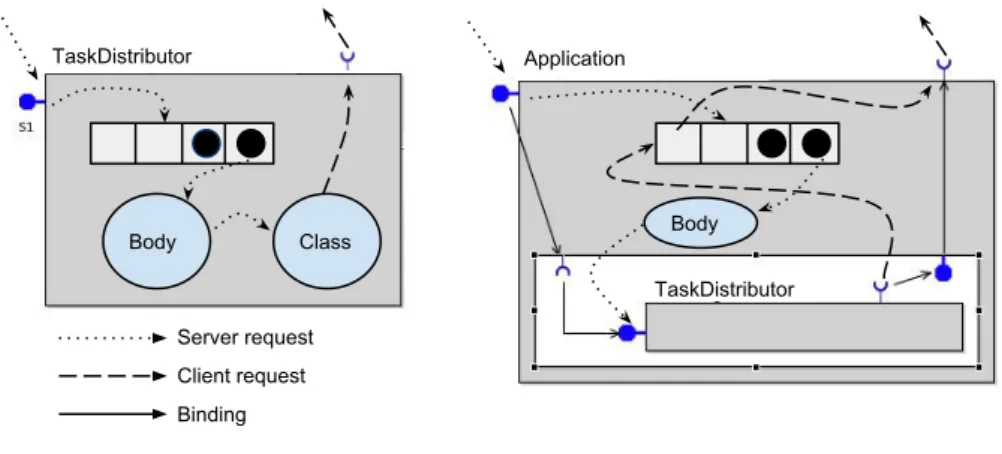
Body Class Body
Server request
Binding
GCM/ProActive Primitive GCM/ProActive Composite Client request
TaskDistributor Application
TaskDistributor
Figure 2.3 – Request treatment by GCM/ProActive components
the first-class futures.
From active objects to components. From the high-level point of view, a GCM/ProActive primitive is implemented as an active object that comprises all the features discussed above. By default, the incoming requests are served in FIFO order, but this can be modified by the programmer. Figure 2.3 illustrates treatment of re-quests by the GCM/ProActive components. The body of a primitive selects a request from the queue and forwards it to its Java class that implements the corresponding behaviour of the primitive. When the request has been processed, the body selects the next request from the queue. If a primitive invokes a remote method, the call is forwarded from the Java class to the client interface and then to the target compo-nent. If the method is supposed to return a result, the corresponding future object is created. A composite is also an active object and it has an implementation class that can be used for configuring some specific parameters, but it does not implement any logic. All requests to the external server interfaces are first dropped in the queue of the composite and then the body forwards them to the subcomponents that are bound to the corresponding server interface. The client requests from the subcom-ponents to outside of the composite are also dropped in the queue of the composite and then distributed among the corresponding client interfaces.
More technically, in order to wrap an active object into a GCM primitive, the programmer has to decide which methods of the active object can be called exter-nally, or, in terms of GCM, which methods of the primitive will be accessible on the external server interfaces. Those methods are then composed into Java interfaces. Each Java interface will be later associated to possibly multiple GCM interfaces and there is no correlation between their names. Then, the programmer writes a Java
2.1. THE GRID COMPONENT MODEL 21
class implementing the behaviour of the primitive. The class is supposed to imple-ment the Java interfaces associated with the GCM server interfaces of the primitive and a set of auxiliary interfaces. An example of a possible implementation of the TaskDistributor primitive from Figure 2.1 is given in the Listing 2.2. The class should at minimum include the following definitions:
• the references to the client interfaces (line 7); • the local variables;
• the attributes that will be exposed by the Attribute Controllers (line 5); • the methods to access the attributes (lines 35-36);
• the methods that are exposed on the server interfaces (lines 10-15);
• the auxiliary methods dealing with the client interfaces and bindings (lines 17-32);
• the local methods
Multi-threaded active objects and primitive components. Significant work has been done on the theoretical and practical aspects of the multi-threaded active objects [28, 29] which are already implemented in ProActive and can serve as the basis for the multi-threaded GCM primitives. The work presented in this thesis supports only single-threaded primitives, but specification and analysis of the multi-threaded primitives is kept for the future work.
Constructing and using components. There are two ways to construct a GCM application in ProActive: either manually or using a factory. In the first case, the pro-grammer invokes the GCM/ProActive API to create components with all necessary characteristics, to add subcomponents in the composites and to connect interfaces with bindings. This approach is not applied in this thesis. Instead, we rely on the second method where an application is constructed by a dedicated factory. The fac-tory takes an ADL file with the system architecture, a set of Java classes implementing primitives’ behaviour, a set of Java interfaces declaring the methods of the GCM in-terfaces and creates automatically all necessary elements including components at different levels of hierarchy controllers and bindings.
When we explained the structure of an ADL file, we did not mention how it is linked to the actual implementation because this is related to the underlying mid-dleware. In the case of a GCM/ProActive ADL (example in the Listing 2.1), the
1public classTaskDistributorClass implements Serializable, BindingController, 2 TDAttributeController, ServerInterface{
3
4 //an attribute accessible from outside 5 public intmyId;
6 //client interfaces 7 publicClientInterface C1; 8
9 //methods of the server interfaces 10 public intrun() {
11 IntWrapper x = C1.task1(); 12 //do something 13 inty = x.getValue(); 14 returny; 15 } 16
17 //auxiliary methods for the management of bindings and interfaces 18 public voidbindFc(String myClientItf, Object serverItf) { 19 switch(myClientItf) {
20 case”C1”: C1 = serverItf; 21 ...}
22 publicString[] listFc() { 23 return newString[1]{”C1”}; 24 ...}
25 publicObject lookupFc(String myClientItf) { 26 switch(myClientItf) {
27 case”C1”: return C1; 28 ...}
29 public voidunbindFc(String myClientItf) throws NoSuchInterfaceException { 30 switch(myClientItf) {
31 case”C1”: C1 = null; 32 ...}
33
34 //methods to manage the attributes 35 public voidset myId(int newId) {...} 36 public intget myId() {...}
37}
Listing 2.2 – A Java class of a GCM/ProActive primitive
programmer has to associate a primitive and a Java class implementing its behaviour (line 6), a GCM interface and a Java interface with its method signatures (lines 4, 5), a list of attributes of a primitive with a Java interface providing access to them (line 7).
Given an ADL file, Java classes and interfaces, the GCM/ProActive factory re-turns an instance of the root component as illustrated in the Listing 2.3. Here, line 1 gets an instance of the factory which will create the component. The factory is asked to construct a new component at line 5; it takes two arguments: the context which stores the description of the deployment infrastructure (we omit the details here) and the name of the ADL file. Next, the constructed component should be ”started”. GCM/ProActive has an implementation of the Lifecycle controller able to start a component as illustrated at line 6. The user can then get a server interface of the constructed component by name (line 7) and invoke its methods (line 8). Addition-ally, the user can use the standard API to modify the root component and bind it to the other components.
2.1. THE GRID COMPONENT MODEL 23
1Factory f = FactoryFactory.getFactory(); 2String adl = ”Application.adl”;
3Map<String, Object> context = new HashMap<String, Object>(); 4//fill the context with the deployment data
5Component application = (Component) f.newComponent(adl, context); 6GCM.getLifeCycleController(mainComponent).startFc();
7RunItf itf = (RunItf)(component.getFcInterface(”s it1”)); 8itf.run();
Listing 2.3 – A GCM/ProActive component construction and access
Overall, specifying GCM/ProActive applications manually can sometimes require significant effort as the programmer has to take care of the coherency between the ADL description, Java classes and interfaces. In order to facilitate the development process, VerCors generates all elements of the application automatically from the user-defined graphical specification.
Distributed deployment. The GCM components can be deployed in a distributed manner where a primitive component is a unit of distribution. The underlying in-frastructure is specified as a composition of virtual nodes that express the abstract references to the resources where the components will be deployed. The virtual nodes are then associated to the exact physical infrastructure. The information about vir-tual nodes can be specified either with Java API or in the ADL file. The physical infrastructure should be provided in an XML-based file and given to the GCM factory when the component is being constructed (lines 3-5, Listing 2.3.
Collective communications. GCM/ProActive provides an API for multicast and gathercast interfaces with the corresponding controllers and several policies on dis-patching request arguments and assembling results. At the current stage, the VerCors platform deals only with the multicast interfaces for which an outgoing request is
repli-cated and sent to all the bound targets and the results are collected in a list and given back to the requester. Implementing other policies will be necessary in the future
work.
Non-functional aspect. The predefined controllers are implemented in GCM/ProAc-tive and the user has access to them. For example, line 6 of the Listing 2.3 demon-strated invocation of a Lifecycle controller that starts a component. Except from that, the user has two ways to implement his customized controllers: as object-controllers or as component-object-controllers. Both of them should be inserted in the component membrane and specified in the ADL file. As opposed to the objects, the component-controllers can have hierarchical structure and communicate with the
other subcomponents. ProActive implements the reconfiguration primitives defined in the CM specification.
2.2
Parameterised networks of synchronised
au-tomata (pNets)
In this section we present the parameterised networks of synchronised automata (pNets) - an intermediate formalism that we will use in this work to encode the behaviour of GCM components.
2.2.1
Term algebra and notations
In the following definitions, we extensively use indexed structures (maps) over some countable indexed sets. The indices will usually be integers, bounded or not. Such an indexed family is denoted as follows: ai∈I
i is a family of elements ai indexed over
the set I. Such a family is equivalent to the mapping (i �→ ai)i∈I. To specify the
set over which the structure is indexed, indexed structures are always denoted with an exponent of the form i ∈ I (arithmetic only appears in the indices if necessary). Consequently, ai∈I
i defines first I the set over which the family is indexed, and then
ai the elements of the family.
For example ai∈{3} is the mapping with a single entry a at index 3; exceptionally,
such mappings with only a few entries will also be denoted (3 �→ a). When this is not ambiguous, we shall use abusive vocabulary and notations for sets, and typically write “indexed set over I” when formally we should speak of multisets, and “x ∈ Ai∈I
i ”
to mean ∃i ∈ I. x = Ai. An empty family is denoted []. To simplify equations, an
indexed set can be denoted M instead of Ml∈L
l when L is not meaningful.
In all forthcoming definitions, we suppose that we have a fixed set of variables, used to construct the expressions of our term algebra. Our models rely on the notion of parameterised actions. We leave unspecified the constructors of the algebra that will allow building actions and expressions used in our models. Let us denote Σ the signature of those constructors, and T be the term algebra of Σ over the set of variables P . We suppose that we are able to distinguish inside T a set of action terms (over variables of P ) denoted A (parameterised actions), a set of data expression
terms (disjoint from actions) denoted E, and, among expressions, a set of boolean expressions (guards) denoted B. For each term t ∈ T we define vars(t) the set of
variables of t.