HAL Id: tel-01081066
https://tel.archives-ouvertes.fr/tel-01081066
Submitted on 6 Nov 2014
HAL is a multi-disciplinary open access archive for the deposit and dissemination of sci-entific research documents, whether they are pub-lished or not. The documents may come from teaching and research institutions in France or abroad, or from public or private research centers.
L’archive ouverte pluridisciplinaire HAL, est destinée au dépôt et à la diffusion de documents scientifiques de niveau recherche, publiés ou non, émanant des établissements d’enseignement et de recherche français ou étrangers, des laboratoires publics ou privés.
application to hadrontherapy
Xavier Lojacono
To cite this version:
Xavier Lojacono. Image reconstruction for Compton camera with application to hadrontherapy. Imag-ing. INSA de Lyon, 2013. English. �NNT : 2013ISAL0126�. �tel-01081066�
Numéro d’ordre:
2013-ISAL-0126 Année 2013
THÈSE
présentée devant
L’Institut National des Sciences Appliquées de Lyon
pour obtenir
LE GRADE DE DOCTEUR
ÉCOLE DOCTORALE : ÉLECTRONIQUE, ÉLECTROTECHNIQUE, AUTOMATIQUE Spécialité : STIC Santé
Soutenue publiquement le 26 Novembre 2013 par
Xavier LOJACONO
Ingénieur ENSEIRB
Image reconstruction for Compton
camera with application to
hadrontherapy
Jury
Irène BUVAT Directeur de Recherche CNRS, Universités Paris 7 et 11 Rapporteur
Magdalena RAFECAS Professor, University of Valencia Rapporteur
Denis DAUVERGNE Directeur de Recherche, CNRS, Université Lyon 1 Examinateur Laurent DESBAT Professeur, Université Joseph Fourier, Grenoble Président du jury
Jean-Michel MOREAU Professeur, Université Lyon 1 Examinateur
Voichiţa MAXIM Maître de Conférences, INSA Lyon Co-directeur de thèse
Remerciements
Je ne savais pas trop comment démarrer ces remerciements alors je me suis dit que le plus simple serait d’écrire les choses comme elles viennent, à la volée. Donc il ne s’agit pas d’un classement réfléchi, mais plutôt d’une longue liste de personnes qui m’ont aidé de quelque manière que cela soit au cours de ces 3 années de thèse...
Commençons donc par ces personnes sans qui ces travaux n’auraient pas pu avoir lieu, mes encadrants Voichiţa Maxim et Rémy Prost. Un grand merci pour tout, la confiance, ainsi que l’opportunité que vous m’avez proposée à la suite de mon stage au laboratoire CREATIS. Ces travaux ont été conséquents et votre soutien m’a permis d’aller au bout de ces 3 années. Il reste tant à faire, mais si j’ai appris une chose c’est que le plus important dans la recherche n’est pas de voir tout ce qu’il y a encore à accomplir comme un obstacle mais plutôt comme une chance d’aller toujours plus loin. Donc un grand merci à vous.
Il convient alors que mes remerciements vont aussi à toutes les personnes qui ont composé mon jury de thèse et qui ont pu me permettre de franchir cette étape finale de la vie du doctorant. Mes remerciements donc d’abord aux rapporteurs, Magdalena Rafecas et Irène Buvat, mais également aux autres membres, Laurent Desbat, Denis Dauvergne et Jean-Michel Moreau.
Les travaux ont été conduit en lien avec le projet ETOILE et donc conjointement avec le laboratoire IPNL. Ainsi je remercie également Marie-Hélène Richard, Jean-Luc Ley, Etienne Testa, Jochen Krimmer d’une part mais également Marianne Tery d’autre part ainsi que Jean-Michel Létang.
Comme cela est parti, je vais sûrement oublier des personnes, je m’en excuse d’avance. J’ai l’impression de devoir citer l’intégralité du laboratoire CREATIS, et ce n’est pas peu dire, car c’est dans une ambiance des plus sympathiques que j’ai passé ces 3 années et ce aussi bien grâce aux chercheurs/doctorants/ingés que grâce au personnel du labo. Commençons par le personnel du labo, avec un grand merci à Marion, Flora, Coupat (Troopa) - JB - Cécilia (le trio fantastique), Christiane, Nadzeu, Fabrice et Pierre (pour le pc et le cluster) et Jérôme.
En ce qui concerne les chercheurs/ingés, merci à Olivier et Olivier, Thomas, Denis, Adeline, Elisabeth, Hervé, Maciej, Sébastien, Didier et Claire.
Passons à ces délinquants de docteurs/doctorants. Ils ont eu beau dénigrer mes boules blanches sur fond noir, je tenais à remercier tous ces vilains petits canards ! Merci donc à mes prédécesseurs et mentors...non, en fait juste prédécesseurs, hahaha! Dbbek, Maria (95001), Chris (Oppa salsa style ?), Simon (merci aussi pour la rando neige...), François (ouiii j’ai plein d’amiEs et alors !), Niaf-Niaf (qui je suis sûr devait stresser pour moi le jour de la soutenance, et juste pour le plaisir, "Merki"), et Rémy...oups, une erreur s’est glissée, Rémy n’est, techniquement, pas un prédécesseur. Allez mon vieux, il va vraiment falloir t’y mettre là... Mouhahaha!
Il y a eu plein de petits jeunots arrivés pour prendre la relève, Hector (Macheteee), ShengFuuuu (qui est complètement fouuu !!), Mae (Help meee), Toulemonde, Estelle (sa
de différentes cultures, et j’ai pu pleinement profiter de cet aspect pendant 3 ans... je tiens à dire : multumesc à Valentina, Elena (te pup papa!), Andreea, Razvan, Anca şi Alina, gracias à Juan (Carlos y Gabriel), Ricardo, Carolina, Diego, William y Alfredo (Yo no soy el tio...), xiè xiè à Pei Dong, Fang Lue, Li Hui, Yang Feng, HongYing, Yue Zhao, XinXin. Une communauté (malheureusement moins) connue du public devrait aussi être à l’honneur, car elle aussi possède cette richesse culturelle : l’Association des Doctorants de l’Insa de Lyon (ADIL). Merci à vous les amis ADILiens, Romain (En avant pour le CCE...ou la thèse... faudra faire un choix à mon avis), Johan, Dimitri, Julien, Clément, Aurélien, Guillaume (ENSEIRB...,ENSEIRB... tu connais la suite).
Á présent, je pense qu’un merci à mon entourage s’impose car ce dernier a pas mal joué sur la conduite de ces travaux. Comment ne pas remercier mes parents pour avoir mis au monde ce petit chef d’œuvre que j’incarne...heu...hum...bref, merci à eux pour leur soutien, et merci à mes frangins...la compétition a parfois du bon (heu, j’ai gagné, non?). Merci à ma Lisa (Choubidou) qui a du supporter l’homme des cavernes que je suis devenu lors de la rituelle hibernation de 3ème année. Ces travaux c’est aussi grâce à toi, donc quelque part, tu es aussi docteur. Au passage, merci aux Patchawaks et compagnie. Merci aussi aux amis, Aurélien, Mélo, Adeline, Mémo, Paula, Jean...et caetera desunt.
Je ne sais pas si j’ai oublié des gens (merci et désolé pour l’oubli), mais il y a une in-stance à remercier également...car sans elle, cette thèse n’aurait pas pu aller à son terme...et surtout les susnommés vilains petits canards me l’ont expressément demandé...alors : merci Youtube...premier fournisseur de vidéos stupides, mais également, la source de toutes mes playlists musicales.
Résumé
La caméra Compton est un dispositif permettant d’imager les sources de rayonnement gamma. Les avantages de ce système résident dans sa sensibilité, en raison de l’absence de collimateur mécanique, mais également dans la possibilité de reconstruire des images 3D avec un dispositif immobile. Ce système est également adapté pour des sources à large spectre énergétique. Ses avantages en font un candidat prometteur en médecine nucléaire (Single Photon Emission Computed Tomography) et en hadronthérapie. Cependant, les méthodes de reconstruction sont plus complexes que celles des modalités d’imagerie tra-ditionnelles.
Ces travaux, financés par le projet européen ENVISION (European NoVel Imaging Systems for ION therapy) Coopération-FP7, portent sur le développement de méthodes de reconstruction d’images pour la caméra Compton. La surveillance de la thérapie par ions nécessite idéalement une reconstruction des images en temps réel avec une précision millimétrique, même si le nombre de données acquises est relativement faible.
A partir de la caméra Compton, on obtient des projections coniques de la source de photons. Nous avons développé des méthodes analytiques et itératives afin de reconstruire la source à partir de ces projections. Leurs performances sont analysées dans le contexte d’acquisitions réalistes: géométrie de la caméra, nombre d’événements, . . . . Nous avons développé une méthode analytique de rétroprojection filtrée. Cette méthode est rapide mais nécessite beaucoup de projections. Nous avons également développé des méthodes itératives utilisant un algorithme de maximisation de la fonction de vraisemblance. En comparaison avec les méthodes analytiques, les méthodes itératives permettent de prendre en compte les propriétés statistiques des données et la configuration du détecteur via la matrice de formation de l’image(matrice système). Nous avons proposé un nouveau modèle probabiliste pour l’estimation des éléments de cette matrice et différentes approches pour le calcul de ses éléments: l’une néglige les incertitudes de mesure, l’autre prend en compte ces incertitudes en utilisant une distribution gaussienne. Nous avons également proposé une méthode simplifiée (donc plus rapide) utilisant notre modèle probabiliste. La nouveauté des méthodes proposées repose aussi sur le calcul des éléments de la matrice par une discrétisation spécifique des projections coniques. Plusieurs reconstructions sont menées à partir de données simulées, que nous avons obtenues avec Geant4, et aussi de données provenant de plusieurs prototypes simulés de caméra Compton proposés par l’Institut de Physique Nucléaire de Lyon (IPNL) et par le Centre de recherche de Dresde-Rossendorf en Allemagne. Les résultats sont prometteurs et des études plus poussées, à partir de données encore plus réalistes, viseront à les confirmer.
The Compton camera is a device for imaging gamma radiation sources. The advan-tages of the system lie in its sensitivity, due to the absence of mechanical collimator, and the possibility to reconstruct 3D images with a stationary device. This system is also well suited for imaging wide energy spectrum sources. These advantages make it a promising candidate for application in nuclear medicine (Single Photon Emission Computed Tomog-raphy) and hadrontherapy. However, the reconstruction methods are complex compared to conventional modalities.
Funded by the european project ENVISION (European NoVel Imaging Systems for ION therapy) FP7-Cooperation Work Program, this work deals with the development of image reconstruction methods for the Compton camera. Ideally, ion therapy monitoring requires real time reconstruction of images with a millimeter accuracy even when the number of acquired events is relatively low.
From the device, we obtain cone-surface projections of the gamma source distribution. In this work, we developed both analytical and iterative methods in order to reconstruct the source from these cone-surface projections. Their performances are analyzed with regards to the context (geometry of the camera, number of events). We developped an analytical method using a Filtered BackProjection (FBP) formulation. This method is fast but really sensitive to the noise. We have also developped iterative methods using a List Mode-Maximum Likelihood Expectation Maximization (LM-MLEM) algorithm. In contrast with analytical methods, the iterative ones enable to take into account the statistical properties of the data and the configuration of the detector through the system matrix. We have proposed a new probabilistic model for the computation of the elements of the system matrix and different approaches for the calculation of these elements: an approach neglecting the measurement uncertainties; another taking into account these uncertainties using a Gaussian distribution. We also implemented a simplified method using the probabilistic model we proposed. Apart from the model, the novelty of the method lies on the specific discretization of the cone-surface projections. The methods are tested on cameras simulated with MEGAlib (based on Geant4) and the influences of the size pf the camera, of the model, and of the number of events are evaluated. Then, several studies are carried out on data simulated from prototypes of Compton cameras under study at the Institut de Physique Nucléaire de Lyon (IPNL) and at the Research Center of Dresden-Rossendorf, respectively. Results are promising, and further investigations on more realistic data are to be done.
INSA Direction de la Recherche - Ecoles Doctorales – Quinquennal 2011-2015
SIGLE ECOLE DOCTORALE NOM ET COORDONNEES DU RESPONSABLE
CHIMIE
CHIMIE DE LYON
http://www.edchimie-lyon.fr
Insa : R. GOURDON
M. Jean Marc LANCELIN Université de Lyon – Collège Doctoral Bât ESCPE
43 bd du 11 novembre 1918 69622 VILLEURBANNE Cedex Tél : 04.72.43 13 95
[email protected] E.E.A. ELECTRONIQUE, ELECTROTECHNIQUE, AUTOMATIQUE
http://edeea.ec-lyon.fr
Secrétariat : M.C. HAVGOUDOUKIAN [email protected]
M. Gérard SCORLETTI Ecole Centrale de Lyon 36 avenue Guy de Collongue 69134 ECULLY
Tél : 04.72.18 60 97 Fax : 04 78 43 37 17 [email protected]
E2M2 EVOLUTION, ECOSYSTEME, MICROBIOLOGIE, MODELISATION
http://e2m2.universite-lyon.fr
Insa : H. CHARLES
Mme Gudrun BORNETTE CNRS UMR 5023 LEHNA
Université Claude Bernard Lyon 1 Bât Forel
43 bd du 11 novembre 1918 69622 VILLEURBANNE Cédex Tél : 04.72.43.12.94
[email protected] EDISS INTERDISCIPLINAIRE SCIENCES-SANTE
http://ww2.ibcp.fr/ediss
Sec : Safia AIT CHALAL Insa : M. LAGARDE
M. Didier REVEL Hôpital Louis Pradel Bâtiment Central 28 Avenue Doyen Lépine 69677 BRON
Tél : 04.72.68 49 09 Fax :04 72 35 49 16 [email protected]
INFOMATHS INFORMATIQUE ET MATHEMATIQUES
http://infomaths.univ-lyon1.fr
M. Johannes KELLENDONK Université Claude Bernard Lyon 1 INFOMATHS Bâtiment Braconnier 43 bd du 11 novembre 1918 69622 VILLEURBANNE Cedex Tél : 04.72. 44.82.94 Fax 04 72 43 16 87 [email protected] Matériaux MATERIAUX DE LYON Secrétariat : M. LABOUNE PM : 71.70 –Fax : 87.12 Bat. Saint Exupéry [email protected]
M. Jean-Yves BUFFIERE INSA de Lyon
MATEIS
Bâtiment Saint Exupéry 7 avenue Jean Capelle 69621 VILLEURBANNE Cédex
Tél : 04.72.43 83 18 Fax 04 72 43 85 28 [email protected]
MEGA MECANIQUE, ENERGETIQUE, GENIE CIVIL, ACOUSTIQUE
Secrétariat : M. LABOUNE PM : 71.70 –Fax : 87.12 Bat. Saint Exupéry [email protected]
M. Philippe BOISSE INSA de Lyon
Laboratoire LAMCOS Bâtiment Jacquard 25 bis avenue Jean Capelle 69621 VILLEURBANNE Cedex
Tél :04.72.43.71.70 Fax : 04 72 43 72 37 [email protected]
ScSo ScSo*
M. OBADIA Lionel Sec : Viviane POLSINELLI Insa : J.Y. TOUSSAINT
M. OBADIA Lionel Université Lyon 2 86 rue Pasteur 69365 LYON Cedex 07 Tél : 04.78.69.72.76 Fax : 04.37.28.04.48 [email protected]
Contents
Résumé v
Abstract vi
Contents xii
List of symbols xiii
I General Introduction 1 Introduction (français) 3 Objectifs. . . 3 Organisation du manuscrit. . . 3 1 Introduction 7 1.1 Objectives . . . 7 1.2 Thesis organization . . . 8 II Compton imaging 11 Résumé en français (Abstract in French) 13 Imagerie Compton . . . 13
État de l’art. . . 13
2 Hadrontherapy 19 2.1 Treatment . . . 20
2.2 Monitoring: state of the art . . . 20
3 Fundamentals of particle physics and γ-ray detection devices 23 3.1 Interaction of gamma rays . . . 23
3.1.1 Photoelectric absorption . . . 24
3.1.2 Compton scattering . . . 24
3.1.3 Electron-positron pair creation . . . 26
3.2 Detection of gamma photons . . . 27
3.3 Gamma cameras . . . 28
3.3.1 Anger camera . . . 28
3.3.2 Compton camera . . . 28
4.1.1 Direct reconstruction with a restricted set of cone surface projections 32
4.1.2 Direct reconstruction using a full set of available projections. . . 34
4.1.3 Expansion in spherical harmonics . . . 34
4.2 Iterative methods . . . 36
4.2.1 The LM-MLEM algorithm. . . 36
4.2.2 Algebraic Reconstruction Technique (ART) . . . 40
4.2.3 Bayesian image reconstruction . . . 40
4.2.4 Stochastic Origin Ensemble (SOE) . . . 41
III Analytical method 43 Résumé en français (Abstract in French) 45 Inversion de la transformée Compton . . . 45
Rétroprojection filtrée pour imagerie Compton . . . 45
Résultats . . . 45
5 Filtered Backprojection algorithm 53 5.1 Compton transform . . . 53
5.1.1 Model for the Compton camera . . . 53
5.1.2 Model of the projections . . . 54
5.2 Parameterization of the forward projection problem. . . 56
5.2.1 Parametrization of the Compton cone . . . 56
5.2.2 Expression of the projections . . . 58
5.2.3 Dual expression of the projections . . . 58
5.3 Inversion of the Compton transform . . . 59
5.3.1 Hankel Fourier Transform . . . 59
5.3.2 Projection slice theorem . . . 60
5.3.3 Inversion formula . . . 60
5.4 Filtered Back Projection algorithm . . . 61
5.4.1 Mathematical formulation . . . 61 5.4.2 Application of the FBP . . . 63 6 Results 65 6.1 Data simulation. . . 65 6.1.1 Compton camera . . . 66 6.1.2 Simulated source . . . 66
6.1.3 Influence of the number of bins . . . 67
6.2 Finite detector size consequences . . . 68
6.2.1 Quality of the image as function of the angle θg for a small camera . 68 6.2.2 Quality of the image as function of the angle β for a small camera . 71 6.3 Conclusion . . . 76
IV Iterative methods 77
Résumé en français (Abstract in French) 79
LM-MLEM: nouvelle formulation mathématique pour l’estimation de la matrice
système . . . 79
Méthode de sélection des génératrices du cône Compton . . . 79
Résultats . . . 79
7 LM-MLEM: Novel mathematical formulation for the estimation of the system matrix 89 7.1 Probabilistic model for the system matrix elements . . . 90
7.2 Numerical evaluation of the system matrix. . . 95
7.2.1 A model that neglects uncertainties on the energy measurements . . 96
7.2.2 A model that accounts for uncertainties on the energy measurements100 7.3 Simplified method: tij estimation using voxel centers . . . 104
8 Selection of the generatrices 107 8.1 The guiding surface . . . 107
8.2 Conic section tracking: initialization . . . 109
8.3 Conic section tracking . . . 111
8.4 Conic section tracking: discussion. . . 112
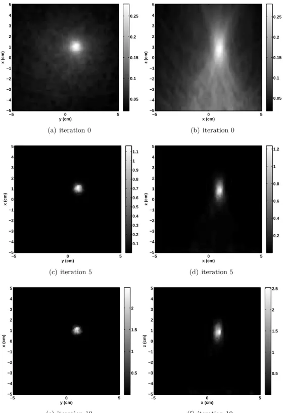
9 Results 115 9.1 Reconstruction of a spherical source . . . 115
9.1.1 Single event back-projections . . . 116
9.1.2 Reconstructions with 5000 events . . . 116
9.2 Influence of the incomplete absorptions. . . 126
9.3 Reconstruction of a line source . . . 131
9.3.1 Context of the simulation . . . 132
9.3.2 Results . . . 132
9.4 Influence of the probabilistic model . . . 138
9.5 Conclusion . . . 142
V Application to ENVISION project 143 10 Application to data from the Institut de Physique Nucléaire de Lyon, France 145 10.1 Compton camera design . . . 145
10.2 Simulations . . . 147
10.3 Low statistics reconstruction of the Compton camera Point Spread Function in 3D prompt-γ imaging of ion beam therapy . . . 147
10.3.1 Source . . . 147
10.3.2 Data . . . 148
10.3.3 Results . . . 148
10.3.4 Point Spread Function . . . 150
10.3.5 Influence of the position of the source . . . 153
11.1 Simulation context . . . 157
11.2 Three Point Sources . . . 158
11.3 Line source . . . 159 11.4 Hot-Cold phantom . . . 161 11.5 Conclusion . . . 164 VI Conclusion 165 Contributions (français) 167 Perspectives . . . 167
12 Conclusions and perspectives 171 12.1 Main contributions . . . 171
12.2 Perspectives . . . 172
List of symbols and abbreviation
List of symbols
h Plank’s constant
me mass of an electron at rest
re classical radius electron
c speed of light
E0 initial energy of a detected photon
E1 energy delivered to the electron during the Compton scattering process
E2 energy of the Compton scattered photon
θM incident angle of the photon emitted at M
C (V1, V2, β) Compton cone of apex V1, axis direction
−−→
V2V1, half-opening angle β
θg polar angle of the Compton cone axis
K(β, E0) Klein-Nishina coefficient accounting for Compton scattering cross
sec-tion
P f Compton projections: cone surface projections
F 1D Fourier transform
F2 2D Fourier transform
HF Hankel-Fourier transform
J0 zero-order Bessel function of the first kind
i index of events
j index of voxels
l index of iterations
vj voxel j
ei event i with the set of parameters (V1, E1, V2, E2)
Nv number of voxels
Ne number of events
Nl number of iterations
λ mean number of emitted photons by the voxel vj
P Poisson law
T = (tij) System matrix
C
µ1,a cross section of total absorption in the scatterer
µ2,a cross section of total absorption in the absorber
σ(E1) energectic resolution of the scatterer
σ(E2) energectic resolution of the absorber
d1 distance travelled by the incident photon until it is scattered
d12 distance travelled by the scattered photon in the scattering detector
d2 distance travelled by the scattered photon in the second detector until it
is absorbed
h spatial kernel, event specific
Abbreviations
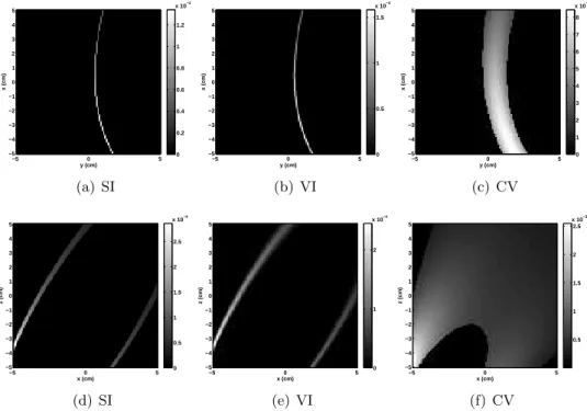
CV Center of Voxel method
SI Surface of Intersection method
VI Volume of Intersection method
NMSE Normalized Mean Squared Error
FWHM Full Width at Half Maximum
LM-MLEM List-Mode Maximum Likelihood Expectation Maximization
ESM Ellipse Stack Method
RTM Ray Tracing Method
IQR Inter Quartile Range
PSF Point Spread Function
ENVISION European NoVel Imaging Systems for ION therapy
Introduction (in French)
Objectifs
Le cancer est une des causes majeures de mortalité dans le monde. En 2008, on comptait 7.6 millions de décès (environ 13% de la mortalité mondiale) dus à cette maladie et environ 12.7 millions de nouveaux cas ont été diagnostiqués. Les plus grands nombres de décès sont provoqués par les cancers du poumon, de l’estomac, du foie, du colon, du sein. D’après les projections, la mortalité due au cancer continuera à augmenter pour atteindre 13.1 millions de décès en 2030, selon les estimations1.
Le traitement de cette maladie nécessite souvent plusieurs interventions soigneusement sélectionnées parmi les différentes techniques telles que la chirurgie, la radiothérapie ou la chimiothérapie. Parfois, ces traitements sont combinés. Dans certains cas difficiles, la chirurgie et la chimiothérapie sont impraticables, la radiothérapie étant alors le traitement le plus approprié. Néanmoins, certaines tumeurs sont radiorésitantes. L’hadronthérapie, qui utilise des particules chargées telles que les ions carbone ou des protons, est une alternative possible. Cette modalité de traitement présente certains avantages par rapport à la radiothérapie, offrant une meilleure balistique et une efficacité accrue vis à vis du dépôt de dose. Cependant, ces avantages requièrent un suivi précis du traitement afin de garantir la sécurité du patient.
L’imagerie médicale fournit plusieurs outils pour effectuer un contrôle du traitement. L’utilisation des techniques d’imagerie est aujourd’hui devenue une méthode essentielle permettant de visualiser l’anatomie ou le métabolisme du corps humain et de suivre le traitement d’une maladie ainsi que sa progression. Utilisant des phénomènes physiques tels que l’absorption des rayons X, la résonance magnétique nucléaire, les ultrasons ou la radioactivité, l’imagerie médicale représente tous les moyens qui permettent d’obtenir des informations sur les organes, les cellules ou les lésions (taille, volume, localisation, forme) ou leur fonctionnement (métabolisme). Ces informations servent ensuite à créer une image exploitable en clinique par le corps médical, pour le diagnostic ou le contrôle.
Pour le suivi de traitements du cancer par hadronthérapie, plusieurs méthodes sont utilisées ou à l’étude. Nous avons par exemple la tomographie par émission de positons (TEP), et la Tomographie d’Emission MonoPhotonique (TEMP). C’est dans ce contexte que le projet European NoVel Imaging Systems for ION therapy (ENVISION) a été lancé
en hadronthérapie. Le projet vise à fournir des solutions pour : la surveillance non invasive en temps réel, l’imagerie quantitative, la détermination précise de la dose administrée, la rétroaction rapide pour une planification de traitement optimale, une réponse en temps réel au mouvement des organes, une série d’études en simulation. Le projet ENVISION est une collaboration de seize centres européens de recherche et des partenaires industriels, coordonnés par le Conseil Européen pour la Recherche Nucléaire (CERN) et sous l’égide de ENLIGHT, the European Network for Light Ion Hadron Therapy.
Dans le cadre de ce projet, le groupe de travail 3 se consacre à l’élaboration d’un dis-positif d’imagerie pour effectuer le suivi du traitement. Plusieurs systèmes sont à l’étude. Parmi eux, la caméra Compton s’avère être un candidat intéressant. Ce système, égale-ment appelé caméra à collimation électronique, permet de détecter, par effet Compton, les photons γ émis par la zone traitée. À partir des mesures réalisées, on peut fournir une image de la source des particules en utilisant des méthodes de reconstruction d’image.
Cette thèse de doctorat s’inscrit dans le cadre des travaux de ce groupe de travail, et plus précisément sur la tâche de reconstruction. L’objectif était de développer des méthodes de reconstruction d’image 3D pour l’imagerie Compton avec application en hadronthérapie. Plusieurs contraintes sont intrinsèques à cette application, en particulier le faible nombre des données recueillies lors du traitement et la surveillance en temps réel. Nos travaux visent à la fois le développement de méthodes analytique et itératives. La contribution principale est double: (i) une méthode de RétroProjection Filtrée pour l’aspect analytique, (ii) un algorithme de maximisation de la fonction de vraisemblance en mode liste pour l’aspect itératif. Pour ce dernier, nous avons proposé un nouveau modèle pour l’estimation des éléments de la matrice système utilisée lors de la reconstruction.
Organisation du manuscrit
Le manuscrit est composé de quatre parties. Dans la première, nous donnons un aperçu de l’hadronthérapie, son histoire et ses avantages. Nous faisons également un état de l’art des méthodes utilisées actuellement pour la surveillance du traitement. Comme nous nous concentrons sur l’imagerie Compton, nous présentons ensuite le fonctionnement de la caméra Compton, en commençant par donner quelques notions fondamentales de la physique des particules. Ensuite nous décrivons les γ caméras. Nous passons en revue par la suite les méthodes pour l’imagerie Compton en présentant un état de l’art des algorithmes analytiques et itératifs.
Dans la deuxième partie, nous nous focalisons sur les méthodes analytiques, en parti-culier les travaux effectués par [Maxim et al. (2009)]. Ces travaux sont le point de départ de notre première contribution, une méthode de rétroprojection filtrée. Nous détaillons ensuite notre méthode et présentons l’outil MEGALib [Zoglauer (2005)] qui nous a per-mis d’effectuer les simulations. Nous complétons l’étude théorique par nos résultats de
reconstructions obtenus à partir de ces données simulées et nous effectuons une étude de l’influence de la taille des détecteurs de la caméra Compton, ainsi que de l’influence de plusieurs paramètres spécifiques à la reconstruction analytique sur la qualité des images.
La troisième partie traite des méthodes itératives basées sur la maximisation de la vraisemblance par maximisation de l’espérance (MLEM). Nous proposons un nouveau modèle probabiliste d’estimation des éléments de la matrice système. L’évaluation de ces éléments est effectuée par le calcul numérique d’une formule d’intégration. Nous proposons d’abord une première approche pour effectuer ce calcul, dans lequel nous ne prenons pas en compte les incertitudes sur les mesures d’énergie de la caméra Compton. Nous détaillons une seconde approche du calcul numérique de la formule intégrale dans laquelle nous prenons en compte ces incertitudes. Nous nous proposons ensuite d’utiliser une méthode simplifiée avec le modèle probabiliste que nous avons établi. Finalement, nous menons une étude sur la reconstruction de sources distinctes tant par la forme que par leur niveau énergétique. Nous discutons de l’influence des caractéristiques du dispositif d’imagerie, du modèle probabiliste proposé ainsi que des incertitudes dues aux absorptions incomplètes des photons par la caméra.
Dans la dernière partie, nous présentons les reconstructions réalisées dans le cadre du projet ENVISION. Différents prototypes de caméra Compton sont actuellement en cours de développement dans plusieurs équipes qui appartiennent au groupe de travail 3. Nous expérimentons alors nos méthodes sur des données obtenues à l’aide de leurs prototypes simulés. Dans un premier temps, nous étudions la réponse impulsionnelle du prototype développé par l’Institut de Physique Nucléaire de Lyon (IPNL), dans le cadre d’une de faible acquisition de données. Nous réalisons dans un deuxième temps, une étude sur les reconstructions 2D des données obtenues à partir du prototype simulé de la caméra Compton développé au centre de recherche de Dresde-Rossendorf, en Allemagne. Cette dernière étude s’inscrit dans le cadre d’une collaboration entre les équipes en charge du développement des algorithmes de reconstruction dans le but de comparer les différentes méthodes proposées au sein du groupe de travail 3 du projet ENVISION. Ce travail est toujours en cours, et nous ne présentons ici que les résultats obtenus à partir de nos méthodes.
Chapter
1
Introduction
1.1
Objectives
Cancer is a leading cause of death worldwide. In 2008, 7.6 million deaths (around 13% of all deaths) was due to this disease and 12.7 million new cases were diagnosed. Lung, stomach, liver, colon and breast cancer cause the most cancer deaths each year. It is expected that deaths from cancer worldwide will rise to over 13.1 million in 20301.
Treatment of this disease often requires more than one intervention and has to be care-fully selected among the different techniques such as surgery, radiotherapy, chemotherapy. In some difficult cases, surgery and chemotherapy are impractical, the tumor is then treated by radiotherapy. Nevertheless, the tumor can be radioresitant. An alternative to classical radiotherapy is then the hadrontherapy technique that uses charged particles such as carbon ions or protons. This treatment modality overcomes radiotherapy by offering an improved ballistics and effectiveness in the dose deposition. However, hadrontherapy requires a precise monitoring in order to guarantee the safety of the patient with regards to the deposited dose.
In this purpose, medical imaging provides several tools to perform a control of the treatment. The use of imaging techniques has nowadays become an essential method that enables to visualize the anatomy or the metabolism of the human body and to follow the treatment of a disease and its progress. Using physical phenomena such as X-ray absorp-tion, nuclear magnetic resonance, ultrasounds or radioactivity, medical imaging represents all the means that enables to recover informations from the organs, cells or lesions (size, volume, localization, shape) or their functioning (metabolism). These informations are
then used to create an image usable in clinical purpose.
Several methods to perform medical imaging for monitoring cancer treatment by hadrontherapy, are investigated such as Positron Emission Tomography (PET), Single Photon Emission Computed Tomography (SPECT), Proton Interaction Vertex Imaging (PIVI). Within this framework, the european project European NoVel Imaging Systems for ION therapy (ENVISION) has been launched in February 2010. This project is funded by the European Commission under FP7 Grant Agreement N. 241851. Its objective is to improve the quality assurance tools for hadrontherapy. In this purpose, the project aims at providing solutions for: real-time non invasive monitoring, quantitative imaging, precise determination of delivered dose, fast feedback for optimal treatment planning, real-time response to moving organs, simulation studies. The ENVISION project is a collabora-tion of sixteen leading European research centres and industrial partners, coordinated by the Conseil Européen pour la Recherche Nucléaire (CERN) and is under the umbrella of ENLIGHT, the European Network for Light Ion Hadron Therapy.
As part of this project, the WorkPackage 3 is dedicated to the development of an imaging device to perform hadrontherapy treatment monitoring. Several system are under investigations. Among them, the Compton camera seems to be a relevant candidate. This system also called the electronically collimated camera, enables to capture γ photons emitted by the treated zone through Compton scattering. From the measures, one may provide an image of the source of γ particles using image reconstruction methods.
This Ph.D thesis falls in the scope of the WorkPackage 3, and more precisely on the reconstruction task. The objective was to develop 3D image reconstruction methods for Compton imaging with application in hadrontherapy. Several constraints are implied by this application: low statistics data, real-time monitoring. This work then addresses both analytical and iterative reconstruction algorithms and the main contribution is twofold: (i) a Filtered Backprojection formulation for the analytical method, (ii) List Mode Maximum Likelihood Expectation Maximization algorithms using a new model for the estimation of the elements of the system matrix required during the reconstruction process.
1.2
Thesis organization
The manuscript is composed of four parts. In the first, we give an overview on the hadrontherapy treatment, its history and advantages. We also present a state of the art of the current monitoring methods used during the treatment. As we focus on Compton imaging, we then present the basics of the Compton camera functioning, starting with the fundamentals of particles physics and describing more generally the γ cameras. Next, we focus on the existing methods to perform Compton imaging. A state of the art of both analytical and iterative algorithms is presented.
In the second part, we focus on the analytical methods. We present the work con-ducted by [Maxim et al. (2009)] on reconstruction from a full set of data acquired by the Compton camera. This work is the starting point of our first contribution, a
Fil-1.2. THESIS ORGANIZATION
tered BackProjection algorithm. We detail the method and give some insights on the tool MEGALib [Zoglauer (2005)] that we used to perform the simulations. We then show re-constructions obtained from the simulated data and we carry out a study on the influence of the size of the Compton device and of several parameters specific to the method on the quality of reconstruction.
The third part deals with the iterative method. We first present the context of ap-plication of the implemented LM-MLEM method. We propose a new probabilistic model for the estimation of the elements of the system matrix. The evaluation of these elements is performed by the numerical evalutation of an integral formula. We propose a first ap-proach that does not take into account energy measurement uncertainties. In a second approach, we do account for these uncertainties, and we obtain another numerical for-mulation. A simplified method that uses our proposed probabilistic model, has also been implemented. We then carry out a study on the reconstructions for two different kind of sources in terms of shape and energy. We analyze the influence of the size of the camera, of the probabilistic model, and also the influence of the incomplete absorptions of photons by the device.
In the last part, we present reconstructions performed within the framework of EN-VISION. Compton camera prototypes are currently under development in several teams that belong to the WorkPackage 3. We experience our methods on data obtained using two simulated prototypes. We study the Point Spread Function of the Compton camera developed by the Institut de Physique Nucléaire de Lyon (IPNL) in France, in case of low statistics data acquisition. We carry out a study on 2D reconstructions with data obtained from simulations using the prototype of Compton camera developed at the Re-search Center of Dresden-Rossendorf, in Germany. This work is part of a collaborative study in the purpose of comparing the different reconstruction methods proposed within the ENVISION project. This work is still in progress.
Résumé en français (Abstract in
French)
Contexte médical
Hadronthérapie
Un des avantages majeurs d’un traitement contre le cancer par hadronthérapie est l’amélioration de la balistique en comparaison à la radiothérapie classique. La dose dis-tribuée par le faisceau dans le patient, présentée figure 2.1, est faible au début de la tra-jectoire. Un pic d’énergie déposée est par la suite observé : le pic de Bragg. Puis la dose diminue drastiquement. Ce profil de distribution très spécifique permet une maximisation du dépôt d’énergie au niveau de la zone tumorale et une minimisation de l’irradiation des cellules saines. Un balayage du faisceau permet de couvrir l’intégralité de la tumeur (fig-ure2.2). Le dépôt très localisé de l’énergie présente aussi l’inconvénient de nécessiter une grande précision. En cas d’erreur de positionnement du patient, d’une mauvaise planifica-tion, de mouvement d’organes, la dose déposée risque d’endommager des cellules saines ou des organes à risques. Le contrôle en ligne est donc une nécessité pour garantir la sécurité du patient. Pour ce faire, nous nous intéressons au rayonnement γ généré par la zone traitée.
Surveillance du traitement: rayonnement γ
Lors du traitement, les réactions nucléaires qui ont lieu au sein de la zone traitée produisent des photons γ de deux types: les γ-prompts et les γ produits par l’annihilation d’une paire électron-positon.
Les γ d’annihilation d’une paire électron-positon qui ont une énergie spécifique de 511 keV, sont émis par paire et se propagent dans des directions opposées. Ces rayons
γ sont détectés au moyen d’un système d’imagerie TEP (Tomographie par Emission de
Positons). Les images reconstruites à partir du scanner TEP sont corrélées à la dose distribuée [Parodi et al. (2007),Moteabbed et al. (2011)] permettant donc de localiser la position du pic de Bragg, i.e. la localisation du maximum de dépôt d’énergie. Les délais entre le traitement et le passage en scanner TEP impliquent une réduction importante du signal pouvant être récupéré. L’examen TEP concomitant avec le traitement permet
l’étude proposant d’effectuer l’acquisition après le traitement mais dans la même pièce pour réduire le délai traitement-acquisition [España et al. (2010)]. Dans le cadre de l’imagerie TEP, la seconde catégorie de photons, les γ-prompts, sont considérés comme une source de bruit.
Les γ-prompts sont de surcroît plus nombreux et représentent une alternative à la TEP au travers de la Tomographie d’Emission MonoPhotonique (TEMP). Les images reconstruites par TEMP sont également corrélées au dépôt de dose [Min et al. (2006),
Testa et al. (2009)]. Le taux d’émission de ces photons serait suffisant pour permettre la surveillance en ligne du traitement [Polf et al. (2009)].
Imagerie Compton
Caméra Compton
Nous nous concentrons sur la détection des γ-prompts par le dispositif appelé caméra Compton. Aussi appelé caméra à collimation électronique, ce système d’imagerie permet la détection des photons par effet Compton. Il fut d’abord proposé pour l’astronomie [Schönfelder et al. (1973)], ensuite pour une application au domaine médical [Todd et al. (1974),Everett et al. (1977)]. En comparaison avec les γ caméras classiques, comme la caméra Anger, l’absence de collimateur mécanique lui confère une meilleure sensibilité. De plus, cette caméra permet de réaliser une image 3D à partir d’un dispositif fixe. Le large spectre couvert par le dispositif en fait également un candidat potentiel pour une application en hadronthérapie, en thérapie par ion carbones ou protonthérapie [Kang and Kim (2009),Frandes et al. (2010),Peterson et al. (2010),Kormoll et al. (2011),Richard
et al. (2011),Robertson et al. (2011),Roellinghoff et al. (2011),Llosá et al. (2011),Richard et al. (2012),Kim et al. (2012)]. Ce système d’imagerie est déjà utilisé en astronomie pour sonder les rayons cosmiques [Bandstra et al. (2011)], ainsi qu’en sécurité territoriale pour détecter les matériaux nucléaires représentant une potentielle menace [Herbach et al. (2009)].
La caméra est généralement composée de deux détecteurs: le diffuseur qui favorise la diffusion Compton et l’absorbeur qui favorise l’absorption par exemple par effet photoélec-trique. Le diffuseur est en général un composé semi-conducteur, en silicium (Si) [Singh and Doria (1983),Solomon and Ott (1988),Kuykens and Audet (1988)] ou en germanium (Ge). Le silicium permet notamment de réduire l’effet Doppler (effet indésirable lors de la détection) et d’avoir une activité thermique plus facile à gérer. L’absorbeur peut être un composé semi-conducteur ou un scintillateur comme des cristaux d’iodure de césium (CsI). Une étude sur la composition de l’absorbeur a été menée dans [Richard et al. (2011)].
Intéressons nous aux interactions physiques mises en jeu. La diffusion Compton est la déviation inélastique d’un photon par un électron libre. Un rayon γ d’énergie Eγ
entre en collision avec l’électron et lui transfère une partie de son énergie Ee. Le photon
est diffusé sous un angle appelé l’angle Compton, noté β, et emporte une énergie E0
γ =
Eγ− Ee. La figure3.3 présente un schéma détaillant l’interaction. L’absorption par effet
photoélectrique est présentée dans la figure3.2. Au cours de cette interaction, un photon γ entre en collision avec un électron lié, une partie de l’énergie du photon Ebest utilisée pour
éjecter l’électron, et le reste Ee est transmis à ce dernier sous forme d’énergie cinétique.
L’espace vacant laissé par l’électron est comblé par un autre électron ou par réarrangement des orbitales atomiques. L’électron à présent libre sera par la suite capturé par le matériau. Modélisation de la détection
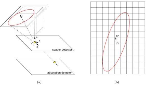
Nous présentons ici la modélisation de la détection d’un photon γ par la caméra Comp-ton. Une particule provenant d’une source de radiation est émise au point M avec une énergie initiale E0. Le photon interagit avec le diffuseur au point V1transférant une énergie
E1 à l’électron. La particule diffusée sous un angle β interagit ensuite avec l’absorbeur
au point V2, déposant une fraction ou la totalité de son énergie restante E2. En
hadron-thérapie, l’énergie initiale des photons est inconnue. De ce fait, on l’estime par la somme des énergies mises en jeu lors de la détection. Cependant, le photon n’est pas toujours totalement absorbé. Ainsi, l’énergie initiale ne sera pas correctement estimée entraînant une erreur sur le calcul de l’angle de diffusion. Ce phénomène aura des répercussions sur la reconstruction et sera discuté au chapitreIV. Dans le cas où le photon subit de multiples diffusions au cours de sa détection, la position d’interaction V2 sera donnée par la seconde
interaction dans les détecteurs, et l’énergie E2 sera également estimée comme étant la
somme des énergies mises en jeu après à la première interaction.
Étant données les deux positions d’interaction V1 et V2, la direction de diffusion est
donnée par le vecteur−−→V2V1. On sait alors que pour des mesures idéales, l’origine du photon,
le point M, se trouve sur la surface du cône de sommet V1, d’axe
−−→
V1V2, et de demi-angle
d’ouverture β, appelé cône Compton et présenté dans la figure 3.6. Lorsque l’on prend les incertitudes de mesure en compte, l’origine du photon ne repose plus sur la surface du cône, mais se trouve à l’intérieur d’un volume entourant cette surface.
Par la suite, à partir des mesures correspondant donc à des projections coniques, le défi est de reconstruire la source de rayonnement γ. Pour cela, plusieurs méthodes ont été proposées, et nous en présentons un état de l’art.
État de l’art
Deux concepts majeurs se dégagent des méthodes proposées pour l’imagerie Compton. On différencie les algorithmes analytiques des algorithmes itératifs.
Dans le cas des algorithmes analytiques, la solution du problème de reconstruction est exacte pour des modèles continus. On approche ensuite cette solution par une discréti-sation adaptée. Une des difficultés associées à ce type d’algorithme est de déterminer un modèle suffisamment proche du problème tout en conservant la possibilité d’en tirer une
Dans le cas des algorithmes itératifs, l’idée est de considérer dès le départ un modèle discrétisé. On utilise ensuite des algorithmes pour approcher la solution. Ces méthodes permettent une plus grande flexibilité vis à vis des paramètres pouvant être pris en compte. Cependant, des problèmes de convergence apparaissent associées à la difficulté de choisir un critère pour l’arrêt des itérations. De plus, la résolution du problème peut parfois demander d’importantes ressources mémoire et des temps de calculs relativement longs. Méthodes analytiques
Les méthodes analytiques ont pour but l’inversion des projections coniques mesurées par la caméra Compton. La première méthode, proposée par [Cree and Bones (1994)], permet d’effectuer la reconstruction à partir d’un ensemble de projections restreint aux cônes d’axe orthogonal au diffuseur. Dans [Basko et al. (1998)], les projections Comp-ton sont transformées en projections planes en utilisant une méthode de développement en harmoniques sphériques. À partir de ces projections planes, la transformée inverse de Radon peut être utilisée à l’instar de ce qui est fait plus généralement en tomodensitométrie (TDM), pour reconstruire l’image 3D de la source. Une reformulation de cette méthode menant à des améliorations du point du vue numérique a été proposée par [Parra (2000)] puis retravaillée par [Tomitani and Hirasawa (2002),Hirasawa and Tomitani (2003)]. Ces travaux utilisent une approche qui consiste à transformer les projections coniques en pro-jection sur des lignes en utilisant une déconvolution en coordonnées sphériques. Par la suite, des méthodes développées pour la reconstruction de ces projections sont utilisées pour reconstruire l’image de la source. L’avantage de la déconvolution permet d’éviter le développement en harmoniques sphériques qui peut demander des ressources informatiques importantes. Une méthode de reconstruction directe à partir de l’ensemble complet des projections Compton mesurées par la caméra a été développée par [Maxim et al. (2009)]. Cet algorithme permet d’aller plus loin qu’avec l’algorithme proposé par [Cree and Bones (1994)] puisque la limitation aux cônes d’axe orthogonal aux détecteurs est levée. Cette méthode est le point de départ de la Rétroprojection Filtrée que nous proposons.
Méthodes itératives
Avec les méthodes itératives, il est possible de prendre en compte le caractère aléa-toire de l’émission et du dispositif de détection ainsi que les phénomènes physiologiques d’absorption chez le patient.
L’un des premiers algorithmes développés est la technique de reconstruction algébrique (ART) proposé par [Gordon et al. (1970),Herman and Lent (1976),Singh and Doria (1983)]. Ce dernier utilise une approche algébrique linéaire pour effectuer la reconstruction. Une information a priori peut facilement être intégrée, mais si on souhaite être plus proche de conditions réelles, la technique nécessite des modifications supplémentaires.
La plupart des autres techniques itératives visent à estimer le maximum de vraisem-blance par maximisation de l’espérance (MLEM) [Hebert et al. (1990),Wilderman et al. (1998),Sauve et al. (1999),Tornga et al. (2009)]. Sa variante OSEM accélère les calculs en distribuant les données dans des sous-ensembles ordonnés [Hudson and Larkin (1994),Kim
et al. (2007),Kim et al. (2010)]. Ces méthodes sont basées sur l’estimation de l’image à l’état suivant en fonction de l’image à l’état courant suivant une formule mettant en jeu les éléments de formation de l’image ou matrice système. Ces méthodes présentent diverses limitations telles que les fluctuations des solutions.
D’autres algorithmes de type bayésien, utilisent des approches de maximum a posteriori (MAP) [Lange et al. (1987),Liang et al. (1989),Huesman et al. (2000)] ou d’entropie maximale (ME) [Strong et al. (1990),Strong (2003)]. Dans ces méthodes, une information préalable peut être incorporée dans le processus de reconstruction. Toutefois, elles exigent la tâche difficile de choisir l’information a priori. Une autre approche bayésienne est proposée par [Lee et al. (2008)] utilisant l’algorithme MAP, mais intégrant également une méthode d’Action-Ligne ou un Bloc-Séquentiel. L’étape Action-Ligne ML (RAML) permet d’effectuer une mise à jour spécifique de l’image en utilisant un ensemble disjoint de projections. Le Bloc-Séquentiel EM (BSEM) est une méthode dérivée de OSEM. Une première étape RAML achevée, une régularisation est effectuée en utilisant le gradient de l’information a priori.
Une approche complètement différente, et néanmoins intéressante, est proposée par [Andreyev et al. (2011),Mackin et al. (2012)] avec une méthode d’ensemble d’origines stochastiques. Pour chaque γ détecté, l’origine du photon est choisie aléatoirement sur la surface du cône Compton. Un processus itératif met à jour l’image en déplaçant cette origine selon une fonction de coût. Les résultats sont similaires à ceux obtenus avec MLEM, cependant il existe plusieurs limitations dues à la variance et l’intensité de l’image reconstruite.
Chapter
2
Hadrontherapy
In addtion to the conventional techniques such as surgery, chemotherapy, or when these modalities cannot be used to treat a tumor, radiotherapy is often used in cancer treatment or to prevent relapses. This technique uses ionizing radiations to kill malignant cells. Radiotherapy has proven to be efficient, however not all tumors can be treated with this modality. Some of them are radio-resistant, leaving the treatment not sufficiently effective. Moreover, the dose deposition in the patient, from the entrance area until the tumor, even under strict control, remains a risk. Hadrontherapy is a form of radiotherapy that uses heavy particles called hadrons. Carbon ions and protons are the most commonly used. This treatment modality could be a relevant solution to the mentioned constraints. With the emergence of particle accelerators in the years 1920, treatment of cancer with protons or heavier ions becomes possible. In 1946, Robert R. Wilson is the first to propose to use such beams in cancer therapy. In 1954, at the instigation of Ernest O. Lawrence, a first patient is treated by protontherapy at Berkeley laboratory, using a cyclotron to accelerate the particles. However, even if the idea to use heavy ions emerged soon, it has only been really investigated in the 90’s. Since then, several centers have been built or are under construction. Hadrontherapy centers currently in use or under construction can be found all over the world, e.g.:
• Japan: NIRS-HIMAC (Chiba), HIMBC (Hyogo), GHMC (Gunma), HIMAT (Tosu), i-ROCK (Yokohama), Proton Medical Research Center University of Tsukuba (Tsukuba) • Germany: HIT (Heidelberg), Marburg Center (Marburg), ISL (Berlin), RPTC
(Mu-nich), Westdeutschen Protonentherapiezentrum Essen (Essen) • Italy: CNAO (Pavia), Catania project (Catania)
• United States of America: MGH Francis H. Burr Proton Therapy Center (Boston), University of Florida Proton Therapy Institute (Jacksonville), ProCure Proton Ther-apy Center (Oklahoma), The Roberts Proton TherTher-apy Center (Philadelphia), Hamp-ton University ProHamp-ton Therapy Institute (HampHamp-ton)
• China: Shanghai Proton and Heavy Ion Hospital (Shanghai), IMP (Lanzhou), Wan-jie Proton Therapy Center (Zibo)
• Austria: MedAutron (Wiener Neustadt) • Switzerland: Institut Paul Scherrer (Villigen)
• France: Centre Antoine Lacassagne (Nice), Centre de protonthérapie de l’Institut Curie (Orsay)
There are on going projects in France with the ETOILE project (Espace de Traitement Oncologique par Ions Légers dans le cadre Européen) in Lyon, and Archade (Advanced Resource Centre for HADrontherapy in Europe) in Caen.
2.1
Treatment
Hadrontherapy consists in an effective cancer treatment that overcomes classical ra-diotherapy by an improved ballistics through the specific shape of the distribution of the deposited dose. At the end of the beam range, a maximum of energy is delivered giving rise to the so-called Bragg peak. The figure 2.1 shows the example of Bragg curves for a proton beam at 148 MeV and a carbon ion beam at 270 MeV. The idea is then to select the energy range of the beam in order to maximize the dose deposition in the target and to minimize it for sparing healthy cells, as shown in figure 2.2. This advantage is also the main challenge of this treatment modality. Indeed, the important number of uncer-tainty sources makes the treatment risky. For instance, a shorter penetration depth of the beam will induce severe damage to healthy tissues and underdosage of the tumor. With a too deep range, healthy cells and organ at risk beyond the target might also be severly harmed. An error in the patient positioning or setup, anatomical motion or variations, tumor evolution, abnormal response of the tissues, all lead to uncertainties on the planned region of maximum dose deposition. For these reasons, treatment monitoring is essential. Nevertheless, this treatment modality is even efficient upon tumors that are radio-resistant. The specific use of carbon ions in hadrontherapy also enhances the Relative Biological Effectiveness (RBE) [Ando and Kase (2009)].
2.2
Monitoring: state of the art
Online monitoring of the irradiation is an important issue in hadrontherapy but also a difficult task. Currently, Positron Emission Tomography (PET) is clinically used for
2.2. MONITORING: STATE OF THE ART
Figure 2.1: Depth dose distribution in water for photons at 21 MeV and monoenergetic Bragg curves for a carbon ion beam at 270 MeV and a proton beam at 148 MeV. Source: [Fokas et al. (2009)]
Figure 2.2: Illustration of the Bragg peak, example of a modulated proton beam and carbon ion beam. Source: Centre ETOILE, Lyon
offline monitoring. Typically, a tumor is irradiated using around 107-108 protons or 105
-106 carbon ions per raster position. During the treatment, interaction of incident ions with
the tissue create unstable nuclei. The physical interactions that follow, produce two types of γ particles. Some of them produce prompt-γ emitted by excited nuclear fragments in times much lower than a picosecond. Other fragments produce positrons that annihilate and emit pairs of γ photons of specific energy.
The γ photons from annihilations of electron-positron pairs are detected via PET scanners. Images from these detecting devices are correlated to the dose distributions
[Parodi et al. (2007),Moteabbed et al. (2011)]. However, this modality has several limitations. The data acquisition is a long process. The delays between the treatment and offline PET imaging yield to an important reduction of the signal. Anatomical activity simply due to the metabolism or also the blood perfusion induce an increase of the blood washout effects. In order to avoid these issues, online PET has been investigated. The delays are avoided and blood washout reduced [Parodi et al. (2008)]. However, the specific design of online PET induce a reduction of the spatial resolution and angular coverage of the scanner degrade the provided images. An intermediate concept is also investigated. The in-room PET, which enables to reduce the delays, and thus the blood washout [España
et al. (2010)].
Prompt-γ particles contribute to the noise background in imaging via a PET scanner. An appealing alternative to PET is then in-beam Single Photon Emission Computed Tomography (SPECT) imaging that uses these particles. Although the density map of those prompt-γ photons is still not identical to the map of the deposited dose, it was shown (e.g, [Min et al. (2006),Testa et al. (2009)]) that it should allow computing the position of the Bragg peak. As suggested by Monte Carlo simulation studies, the emission rate of prompt-γ photons may be sufficient for online monitoring [Polf et al. (2009)]. Other online imaging modalities based on prompt secondary radiations were proposed, e.g. Proton Interaction Vertex Imaging [Henriquet et al. (2012)].
Chapter
3
Fundamentals of particle physics and
γ-ray detection devices
Since they are more numerous than photons from annihilation of a pair electron-positron, we focus on prompt-γ photons. In order to better understand how a γ-radiation imaging system works, we first recall in this section fundamentals of some physical pro-cesses taking place during irradiation of matter with charged particles. Then, we describe the functioning of γ cameras.
3.1
Interaction of gamma rays
There are several scenarii that might occur when a γ photon travels through matter: (i) the ray may not interact at all; (ii) the photon can be scattered delivering a part of its energy to the medium it interacts with; (iii) the photon can be absorbed, providing all its energy to the medium and resulting in the annihilation of the particle. Among these different processes, we may find photoelectric absorption, Compton scattering, electron-positron pair creation. The nature of the interaction depends on the medium where the interaction takes place but also on the initial energy of the particle. Figure 3.1 shows the predominant interaction depending on the energy in a Silicon (Si) medium. We can already note the range of energy of the Compton scattering from around tens of keV to tens MeV.
Figure 3.1: Cross-section for photon interactions in Silicon according to the energy of the
γ photon. The dominating interaction is photoelectric effect at low energies, Compton
scattering at energies from about hundreds of keV to ten MeV, pair creation at high energies. Source: [Zoglauer (2005)]
3.1.1 Photoelectric absorption
The photoelectric absorption consists in the interaction of a γ particle of energy from a few eV to over 1 MeV, with an atom of the crossed medium. During the interaction, the photon transfers all its energy to one of the orbital electrons of the atom. Generally, the energy of the γ particle far exceeds the binding energy of the electron involved in the interaction process which leads to its ejection. The γ particle disappears. As for the ejected electron, its kinetic energy Ee is equal to the incoming energy of the photon Eγ
minus the binding energy Eb:
Ee= Eγ− Eb. (3.1)
The vacancy left is then refilled by a nearby free electron. This process liberates the binding energy in the form of a characteristic photon which will also interacts with an electron from less tightly bound shells of the nearby atoms of the medium. The overall process finally consists in the conversion of the photon energy into energies carried by freed electrons. The later are detectable through their Coulomb interactions.
3.1.2 Compton scattering
Compton scattering consists in the inelastic deviation of a photon by a free electron. The photon with an intial energy Eγ, collides with the electron which recoils with a kinetic
energy Ee transferred by the γ particle. The photon is scattered through an angle β and
conserves an energy E0
γ = Eγ− Ee, see figure3.3.
3.1. INTERACTION OF GAMMA RAYS
Figure 3.2: Basic scheme of the photoelectric absorption mechanism. A photon with an energy Eγ interacts with a bound electron which causes the electron to recoil. Eb
corresponds to the energy required to produce the ejection and Ee the energy transferred
to the electron.
Figure 3.3: Basic scheme of the Compton scattering mechanism. A incident photon with an energy Eγ interacts with a electron which causes the electron to recoil. The photon
transfers an energy Ee to the electron and is scattered through the Compton angle β with
a remaining energy of E0 γ. Compton equation: cos(β) = 1 − mec2 1 E0 γ − 1 Eγ ! (3.2) where meis the mass of an electron at rest and c is the speed of light. For a mathematically
valid Compton angle, the following conditions must be verified:
mec2Eγ 2Eγ+mec2 6 E 0 γ6 Eγ 0 6 Ee6 2E2 γ 2Eγ+mec2 (3.3) In this description, it is assumed that the photon interacts with an electron at rest. In reality, this is not the case. This will result in the so-called Doppler broadening that limits the angular precision on the measurement of the Compton scattering angle.
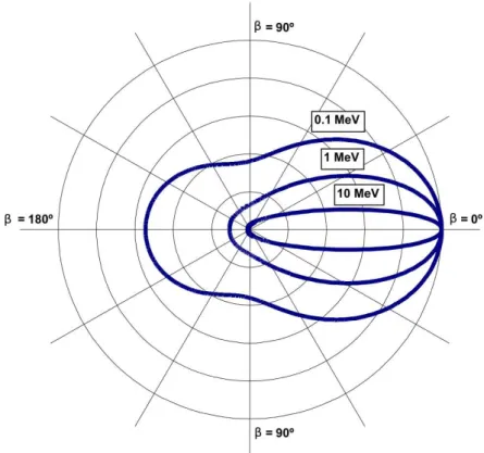
The probability that a photon with an energy Eγ undergoes a Compton scattering
through an angle β is given by the Compton scattering cross-section K(β, Eγ). The
photon that interacts with an unbound electron. K(β, Eγ) = r2e 2 Eγ0 Eγ !2 Eγ0 Eγ + Eγ E0 γ −sin2β ! , (3.4)
with re the classical electron radius given by re = e
2
4πε0mec2 where e is the elementary
charge and ε0 is the permittivity of free space. Since in reality the electrons are bound
to nuclei, it is only possible to approximate the cross-section. In figure 3.4, we present Klein-Nishina cross-section as a function of the Compton scattering for different energies. The greater the initial energy of the photon is, the higher is the probability to have a small scattering angle.
Figure 3.4: Representation of the Klein-Nishina cross section as a function of the Compton angle β at three different energies: 0.1 MeV, 1 MeV and 10 MeV. The higher the energy is, the smaller the average Compton scatter angle is. Source: [Zoglauer (2005)]
3.1.3 Electron-positron pair creation
When its energy is superior to 2mec2, i.e. 1.022 MeV, the γ photon can interact in
the vicinity of a nucleus and create an electron-positron pair. The figure3.5 presents the interaction mechanism.
The interaction can take place only if the situation allows both energy and momentum conservation. The photon is fully absorbed, a part of its energy being converted into the mass of an electron-positron pair, the excess of energy transferred in the form of kinetic
3.2. DETECTION OF GAMMA PHOTONS
energy to the created pair. The nucleus takes over part of the photon momentum. If the photon’s energy is superior to four times the rest mass of an electron, the pair creation can occur in the field of an electron. In this case, the momentum is transferred to this electron.
At the end of its range, the positron combines with an electron and both annihilate, producing two γ-rays of 0.511 MeV, propagating in opposite directions.
Figure 3.5: Basic scheme of the pair electron positron creation mechanism and further positron annihilation. A photon with an energy Eγ superior to 1.022 MeV interacts with
the electric field of a nucleus (or electron) and create an electron-positron pair. The positron interacts then with another electron leading to the creation of two γ particles of energy 511 keV that are emitted in opposite direction.
3.2
Detection of gamma photons
Detection of γ radiation is an important research tool in nuclear medicine and in hadrontherapy. It is achieved through the interactions, previously described, of γ particles with the imaging device. The detectors are mostly based on scintillation or semiconductor materials. As mentioned previously, depending on the initial energy of the photon, one interaction is predominant over the others. The material has also an impact on the type of interaction that will be predominant. For instance, a low atomic material can facili-tate the Compton scattering interaction whereas a high atomic material is well suited for photoelectric absorption.
3.3
Gamma cameras
3.3.1 Anger camera
In 1958, Anger proposed a scintillation device in order to image prompt-γ [Anger (1958)]. Either referred to as Anger camera or gamma-camera, this device has been a major imaging system in nuclear medicine since its development over 40 years ago. Numerous investigations, often specific to a given domain of application, allowed to continuously improve its spatial and energy resolutions.
In the field of in-beam SPECT, several variants of the Anger camera have been investi-gated [Ishikawa et al. (2001),Min et al. (2006),Kim et al. (2007),Testa et al. (2009),Peloso
et al. (2011)]. Generally, the system is composed of a scintillator, with a shield against neutrons from the background, and a collimator to detected γ particles coming from a spe-cific direction. A 1D-profile corresponding to the projection of the prompt-γ production map on the beam direction may be then measured. The concept is appealing, especially when the signal-to-noise ratio is low. However the presence of the collimator limits greatly the particle detection efficiency. In nuclear medicine, typically only one γ ray is observed for every 10000 emissions, because most of particles are absorbed in the collimator [ Bush-berg and Boone (2011)]. Another drawback of the collimator, it necessitates a rotation of the device to perform a full scan.
3.3.2 Compton camera
A new concept was introduced in [Todd et al. (1974),Everett et al. (1977)], a device based on the Compton effect. This kind of system was already investigated for astronomy applications [Schönfelder et al. (1973)]. The Compton camera also called electronically collimated camera enables to produce a 3D image with a stationnary system. It is generally composed of two different detector materials: the scatterer facilitating Compton scattering interactions; the absorber facilitating photoelectric absorptions. The scatterer generally is a semiconductor such as Silicon (Si) [Singh and Doria (1983),Solomon and Ott (1988),
Kuykens and Audet (1988)] or Germanium (Ge). The Silicon seems to be a relevant material since it increases the Compton scattering rate have a good energy resolution but also reduces the Doppler broadening and the thermal activity is easily managed. The absorber is either a semiconductor, or a scintillation detector such as crystals of Caesium Iodide (CsI), Cerium-doped Lutetium Yttrium OrthoSilicate (Ce:LYSO or LSO), Bismuth Germanium Oxide (BGO). Since its proposal, different Compton camera devices have been investigated [Singh and Doria (1985),Singh and Brechner (1990),Gormley et al. (1996),LeBlanc et al. (1999),Sauve et al. (1999)].
The Compton camera is already used in astronomy as a telescope to detect atmospheric or cosmic γ-ray sources [Bandstra et al. (2011)], and is also proposed for homeland security applications concerning the detection of nuclear material which could be a threat [Herbach