HAL Id: in2p3-00097935
http://hal.in2p3.fr/in2p3-00097935
Submitted on 22 Sep 2006
HAL is a multi-disciplinary open access
archive for the deposit and dissemination of
sci-entific research documents, whether they are
pub-lished or not. The documents may come from
teaching and research institutions in France or
abroad, or from public or private research centers.
L’archive ouverte pluridisciplinaire HAL, est
destinée au dépôt et à la diffusion de documents
scientifiques de niveau recherche, publiés ou non,
émanant des établissements d’enseignement et de
recherche français ou étrangers, des laboratoires
publics ou privés.
General design considerations for a high-intensity muon
storage ring for a neutrino factory
C. Johnstone, F. Méot, G.H. Rees
To cite this version:
C. Johnstone, F. Méot, G.H. Rees. General design considerations for a high-intensity muon storage ring
for a neutrino factory. European Particle Accelerator Conference (EPAC’06), Jun 2006, Edinburgh,
United Kingdom. Joint Accelerator Conferences Website, EPAC 2006, pp.2418-2420, 2006.
�in2p3-00097935�
GENERAL DESIGN CONSIDERATIONS FOR A HIGH-INTENSITY MUON
STORAGE RING FOR A NEUTRINO FACTORY *
C. Johnstone
#, Fermilab, Batavia, IL 60510 U.S.A, F. Meot, CEA, France
G. H. Rees
†, CCLRC, RAL, Chilton, Didcot, Oxon, OX11 0QX, U.K.
Abstract
Muon decay ring design, shielding, and compatibility with potential neutrino detector sites are a critical part of the International Scoping Study (ISS) for a Neutrino Factory. Two rings are under development: a racetrack and an isosceles-triangle ring initially for a muon energy of 20 GeV, but upgradable to 40 or 50 GeV. Neutrinos from the muon decays in specially designed production straights can be directed to one or two distant detectors. The racetrack ring has one very long production straight aligned with one detector, while the triangular ring has two shorter straights aligned with two detectors. An initial site survey of accelerator laboratories and distant detectors has been made, along with the required tilt angles for the planes of the rings.. Injection, collimation, and RF system design are covered in this paper. (Lattice studies are covered in a separate contribution to these proceedings.) Heating and activation effects of beam loss in the chamber walls and components will also be presented.
INTRODUCTION
Muon decay rings are under study as part of an International Scoping Study (ISS) for a future Neutrino Factory. Both isosceles triangle and racetrack, shaped rings are being considered for a 20 GeV muon energy, but with upgrade potentials of 40 or 50 GeV. The rings depend on the other stages: a high power proton driver, a pion production target, a system to form and rotate trains of 80 μ+ and 80 μ¯ bunches, an ionisation cooling region, a muon acceleration chain, and, finally, two neutrino detectors at distant locations. Technical choices in the upstream systems and their impact on the storage ring will be elaborated below.
DECAY RING CONSIDERATIONS
Bunch Patterns
In one scenario, the bunch trains are produced by a proton driver consisting of a 200 MeV, H¯ linac, a 0.2-3 GeV, 50 Hz, RCS booster synchrotron and a 3-10 GeV, 50 Hz, NFFAG accelerator (similar to the one in [1] ). The RCS circumference is half the length of the NFFAG injection orbit, while the proton revolution period at 10
GeV in the NFFAG, Tp, is half the muon rotation period,
Td, at 20 (40 or 50) GeV in each decay ring. The periods,
Tp and Td = 2Tp , are chosen to give revolution
frequencies at sub-harmonics of 201.25 MHz, which is the muon acceleration frequency.
Sequential delays of n, RCS bunches allow uniformly spaced bunches in the NFFAG, and further sequential delays in the NFFAG, at 10 GeV, after adiabatic bunch compressions, allow a uniform filling of muon bunch trains into the decay rings. The NFFAG delays may be set at (p + n/5) Td, for p an integer, and n = 1 to 5, for the
case of the five bunch trains, or set at (p + n/3) 2Tp, with n
= 1 to 3, for three bunch trains. By this means, the proton duration at the production target may be varied over a wide range, from a few to a few hundred microseconds. Typically, 34 to 68 μs (2 to 4 times a μ± ring acceleration time) is considered for liquid mercury jet targets, and up to 250 μs for solid metal targets.
The final patterns for each decay ring consist of a set of three, or five, uniformly spaced, 400 ns, trains containing 80 μ+ or 80 μ¯ bunches. Each bunch train injection is estimated to need 14 fast-kicker pulsers per ring. The μ+ and μ¯ bunch trains are injected into separate rings, which are in a common tunnel for the triangular rings, but can be in separate tunnels for the racetracks (easing the task of finding desirable detector sites with appropriate baselines). For triangular rings in a common tunnel the μ+ trains in one ring are interleaved in time with the μ¯ trains in the other. In order for the detectors to resolve the individual trains, 100 ns must be maintained between the interleaved bunches. For racetracks in two different tunnels (each being viewed by a different detector) the interval between bunch trains increases to 600 ns to accommodate not only the train, but also the injection kicker rise and fall time.
Bunch trains are injected into the upstream ends of the production straights nearest to the surface. There is an injection septum magnet just downstream of a first solenoid and 24 m of fast kicker magnets between the second and third solenoids in the triangle ring. Injection also occurs in the straights in the racetrack which is assumed to have mirror symmetry or identical optics in the opposing straights. The estimated number of 5 kA, 50 kV, fast pulse systems to power the kickers is 14, with 2 spares, for each ring.
Decay-Ring Lattice
The circumference of each ring is 1608.8 m, giving a harmonic number, h, relative to the 201.25 MHz, muon acceleration frequency of 1080 (= 23x33x5). The choice is related to the bunch train, filling scheme, and is
____________________________________________
*Work supported by by the Universities Research Association, Inc., under contract DE-AC02-76CH00300 with the U.S. Department of Energy.
#cjj@fnal.gov †ghrees@ukonline.co.uk
compatible with the 10 GeV orbit of the NFFAG. An increase in the number of bunches and storage ring circumference over this value yields little improvement in overall neutrino production.
Proton driver booster ring
(n=, h=40)
Muon bunch train after target
T=sequential delay of the muon bunches O O O O O
Muon trains of 80 bunches
20 GeV muon accelerator with rotation period, Trev
T= mTrev ~ 25 to 50 μs , t = 400 ns
m = number of turns of acceleration
20/50 GeV μ+ decayring (circumference 1600m):
600 400 600 400 600 400 600 400 600 400 (nanosec)
20/50 GeV μ- decayring (circumference 1600m):
400 600 400 600 400 600 400 600 400 600
Figure 1. Proton and Muon Bunch Trains proposed for the ISS Neutrino Factory Study
The downward slope for a production straight aligned to a detector at distance, L, is given by arcsin (L/2R), with R the equatorial radius. For a detector at 7500 km, the downward slope is ~36˚ and, for one at 3500 km, ~16˚. The resulting triangle ring then has a depth > 400m, and an apex angle of ~52˚, if vertical, and a larger apex angle, if not. A racetrack aligned to the 7500 km detector has comparable depth, due to its long production straight. Accelerator and detector sites will be identified in future and it is only then that the ring parameters may be detailed and a choice made between triangle and racetrack rings.
SITE CONSIDERATIONS
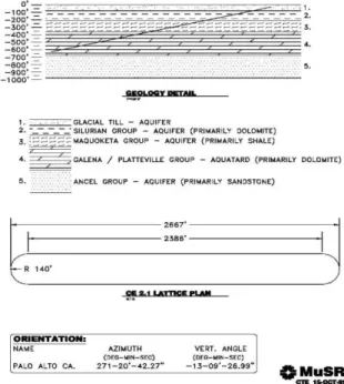
With 400 ns for the bunch train and 100 ns spacing between bunches available for the rise and fall time of the injection, fast kicker magnets, a circumference of 1609 m, for example, is required to accommodate n = 5 bunch trains in a ring. With km-scale circumferences and the depth needed to meet the 7500 km baseline requirement, there are implications as to the geological features of the site which complicate the selection for the storage ring, in particular for the triangular rings as will be discussed. The 1600 m ring attains a vertical depth in excess of 400 m for both the triangle and racetrack rings. For example the attainable depth at Fermilab is only 200m before reaching a soft sandstone strata[2] which cannot support a tunnel and furthermore contains the municipal water supplies as shown in Figure 2.
Figure 2. Constraints on the storage ring due to the geology under the Fermilab site The 2667’ (or 813 meter) limit on the cross-section profile of the ring shown in the lower drawing is given by the 600 foot available for the ring’s vertical drop the and 13° between Fermilab and the West Coast.
The limited circumference must reflect a changed production straight length and reduction in overall neutrino production efficiency (the arcs and matching remain unchanged). With an extra pair of matching sections over the racetrack, the production efficiency triangle eventually drops below that of the racetrack shape. An outline of approximate production efficiencies for the two ring configurations vs. circumference is given in Table 1. Geological considerations ultimately further complicate the site selection, and for certain sites (Fermilab and BNL, for example) the racetrack is the preferred, and in the case of BNL[3], the only choice regardless of detector sites. However, it must be kept in O O O O O T T t
mind that changing the circumference of the storage ring from 1609 m changes completely the filling scheme. Table1. Neutrino production efficiencies as a function of circumference Circumference Triangle 52.8° apex ∠ racetrack 1609 49.6% 38.2% 1258 42.8% 34.9% 944 33.2% 38.2% 804 27.6% 26.3% 629 4.7% 19.7%
COLLIMATION AND LOSSES
Due to e± losses after μ± decays, the warm bores of superconducting, arc magnets are clad with lead or a centimeter of tungsten to absorb the e± power. Direct μ± wall loss also leads to magnet heating. Hence, both rings will have loss collimators, located in four of the central, FODO cells noted in the last section. There will be
horizontal and vertical primary collimators, and secondary collectors downstream, after betatron phase shifts of 20˚, 90˚ and 160˚. Beam activation may be high, so use of room temperature quads, with radiation hard windings, is planned.
REFERENCES
[1] G H Rees, “FFAG Studies for Neutrino Factory Accelerators,” Nuclear Physics B (NuFact 05, Proceedings Supplement) 155 (2006), p 301-304. [2]
N. Holtkamp and D. Finley, eds., “A Feasibility
Study of a Neutrino Source Based on a Muon
Storage Ring”, Fermilab-Pub-00/108-E (2000).
[3]