WASTE MINIMIZATION STUDY ON PYROCHEMICAL REPROCESSING PROCESSES
H. Boussier, O. Conocar, J. Lacquement
CEA/DEN Valrho Marcoule/DRCP/SCPS/Pyrochemical Processes Laboratory BP 17171 30207 Bagnols-sur-Cèze
France
ABSTRACT
Ideally a new pyroprocess should not generate more waste, and should be at least as safe and cost effective as the hydrometallurgical processes currently implemented at industrial scale.
This paper describes the thought process, the methodology and some results obtained by process integration studies to devise potential pyroprocesses and to assess their capability of achieving this challenging objective.
As example the assessment of a process based on salt/metal reductive extraction, designed for the reprocessing of Generation IV carbide spent fuels, is developed.
Salt/metal reductive extraction uses the capability of some metals, aluminum in this case, to selectively reduce actinide fluorides previously dissolved in a fluoride salt bath. The reduced actinides enter the metal phase from which they are subsequently recovered; the fission products remain in the salt phase.
In fact, the process is not so simple, as it requires upstream and downstream subsidiary steps. All these process steps generate secondary waste flows representing sources of actinide leakage and/or FP discharge.
In aqueous processes the main solvent (nitric acid solution) has a low boiling point and evaporate easily or can be removed by distillation, thereby leaving limited flow containing the dissolved substance behind to be incorporated in a confinement matrix. From the point of view of waste
generation, one main handicap of molten salt processes, is that the saline phase (LiF-AlF3 in our
case) used as solvent is of same nature than some of the solutes (radionuclides fluorides) and has a quite high boiling point. So it is not so easy, than it is with aqueous solutions, to separate solvent and solutes in order to confine only radioactive material and limit the final waste flows. Starting from the initial block diagram devised two years ago, the paper shows how process integration studies were able to propose process fittings which should lead to a reduction of the waste variety and flows leading at an “ideal” new block diagram allowing internal solvent recycling, and self eliminating reactants. This new flowsheet minimizes the quantity of inactive inlet flows that would have inevitably to be incorporated in a final waste form. The study identifies all knowledge gaps to be filled and suggest some possible R & D issues to confirm or infirm the feasibility of the proposed process fittings
INTRODUCTION
In the seventies pyrochemical processes were considered as a possible alternative to hydrometallurgical PUREX process for spent fuel reprocessing ; at the time only uranium and plutonium recovery was aimed. Since late nineties with the Advanced Fuel Cycle Initiative (AFCI) and GENRATION IV, a renewed interest raised in pyrochemical processes but with new and more demanding objectives.
Not only uranium and plutonium but all minor actinides (i.e. neptunium, americium and curium) should be separated from fission products for recycling. In order to limit proliferation risks all actinides should be managed together. Lastly a particular attention has to be focused on waste management. Ideally a new pyroprocess should not generate more waste, and should be at least as safe and cost effective as the hydrometallurgical processes currently implemented at industrial scale.
Our process integration studies aim to devise potential pyroprocesses and to assess their capability of achieving these challenging objectives.
This paper describes the thought process, the methodology and some results obtained by these studies. As example the assessment of a process based on salt/metal reductive extraction applied to a GEN IV carbide fuel with SiC cladding, is developed.
PROCESS DESCRIPTION
A general process block diagram is given here after.
Head-end Treatment
Fuel Dissolution
Noble Metals Removal
An Extraction
An Stripping (various possible routes)
Fuel (re)fabrication
Volatile FPs
Noble metals to metallic matrix
(Ni-Cu)
FP/salt separation
Distillated Salt (LiF-AlF3)
Carbide Fuel
HF
metal 1 (e.g. Zn)
(Al or AlCu) Other FP
fluorides AnO2 Al Recycling (LiF-AlF3melt) glass Distillated Zn
Oxidation & Thermal treatment
SiC Head-end Treatment
Fuel Dissolution
Noble Metals Removal
An Extraction
An Stripping (various possible routes)
Fuel (re)fabrication
Volatile FPs
Noble metals to metallic matrix
(Ni-Cu)
FP/salt separation
Distillated Salt (LiF-AlF3)
Carbide Fuel
HF
metal 1 (e.g. Zn)
(Al or AlCu) Other FP
fluorides AnO2 Al Recycling (LiF-AlF3melt) glass Distillated Zn Head-end Treatment Fuel Dissolution
Noble Metals Removal
An Extraction
An Stripping (various possible routes)
Fuel (re)fabrication
Volatile FPs
Noble metals to metallic matrix
(Ni-Cu)
FP/salt separation
Distillated Salt (LiF-AlF3)
Carbide Fuel
HF
metal 1 (e.g. Zn)
(Al or AlCu) Other FP
fluorides AnO2 Al Recycling (LiF-AlF3melt) glass Distillated Zn
Oxidation & Thermal treatment
Figure 1: Global process block diagram
Mechanical treatment
The process begins with a series of head-end operations on the fuel assemblies to obtain an oxide powder that is fine enough (50–100 µm) for the subsequent reductive distillation and fluorination steps. The main difficulty of this step is to limit material losses entrained with the SiC hulls. SiC is a ceramic material that is more brittle and should exhibit very different shearing behavior than ductile steel or Zircaloy cladding. Following the mechanical operations there may be relatively fine cladding debris mixed in with the fuel pellets and oxide fines. Complete separation of the cladding from the oxide exclusively through mechanical processes is difficult to imagine.
The mechanical treatment is highly dependent on the nature of the fuel and cladding. In view of the very preliminary status of this study and the fact that the form and nature of the fuel have not been clearly specified at this time, this process step will not be further discussed in this paper. It is assumed that only a small fraction of the SiC from the clads will be entrained with the oxide
powder. The entrained SiC particles should be eliminated as volatile fluorides (SiF4 and CF4)
during the hydrofluorination step [2].
During these operations some or all of the gaseous or volatile fission products (Kr, Xe, I, Br) are released and must be collected and trapped for disposal as an ultimate wasteform.
Heat treatment
The resulting powder will be heat treated to eliminate the volatile elements. This involves distillation at high temperature (above 1000°C) in controlled atmosphere (argon + 5% hydrogen). During this treatment all the cesium, rubidium and tellurium would be volatilized. Some or all of the Tc, Cd, As, and Se would be also volatilized [3, 4]. Thermal treatment has not yet been tested on irradiated carbide with these experimental conditions.
Hydrofluorination
The oxides are hydrofluorinated with HF as the fluorinating agent. HF generates fluorides at low oxidation states and thus prevents the formation of volatile uranium hexafluoride.
Prior to extraction of the actinides by aluminum based alloy, one option could be to eliminate the zirconium fluoride by volatilization, by heating the fluorides above 800°C. This would be particularly advantageous since Zr represents about 3% of the total negative reactivity of the FP. The volatilization step has not yet been tested.
Dissolution in a LiF-AlF3 salt phase
After the fluorination step the powder is contacted and dissolved at 830°C in a molten salt flow with a composition selected to obtain the required extraction performance. The process was
initially based on a binary salt (from 85 mol% LiF, 15 mol% AlF3 to 65 mol% LiF, 35 mol
Digestion of platinum-group metals
The salt phase is then placed in contact with a mildly reducing metal phase containing zinc possibly or not alloyed with copper and nickel. The platinum-group metals and molybdenum are extracted to the metallic state; these elements, the noble metals, as well as Sb, Ge (?) and Nb (?) are dissolved in the metal phase [3]. Zinc is then recycled by vacuum evaporation; the extracted elements remain in the Ni/Cu alloy. The nickel/copper matrix could constitute an acceptable confinement matrix; this point must be confirmed by a specific study.
Other metal matrices could also be considered, for example Zr/Ni, Cu/Sn or Al. Although some of these have lower potential radionuclide loading capacities than Ni/Cu alloy, it could be advantageous to use a matrix that is entirely constituted by a process waste flow (Al from the metal loop).
Group extraction of the actinides
The salt is then contacted with an Al or Al/Cu metal phase in which aluminum is the reducing metal; copper is added to obtain a heavier metal phase and thus facilitate the separation of the salt and metal phases. It has no chemical role and tests carried out showed that Cu is not indispensable. During this stage almost all the actinides are extracted, together with a small fraction of the fission products present in the salt. A high actinide recovery yield and satisfactory fission product decontamination performance requires a multistage extraction system and suitable salt and metal flow settings. Simulations using the experimentally measured distribution coefficients showed that two theoretical countercurrent stages would be sufficient.
In order to minimize waste generation, salt phase have to be recycled, but to prevent accumulation of fissions products in the salt they have to be previously eliminated by an appropriate (read on, waste management flow chapter).
Recovery of the actinides and preparation of finished products
Two variants can be considered at this point:
• The extracted actinides and FP dissolved in the metal phase are transferred to a
LiCl-KCl or NaCl-CaCl2 salt phase by oxidizing stripping using CuCl2. The actinides
would then be precipitated as oxides by adding lithium carbonate and potassium carbonate, or sodium carbonate and calcium carbonate. The salt and oxide separated by settling (or possibly by filtration or centrifugation) supplemented by low-pressure distillation of the trace amounts of salt entrained with the precipitate. This variant has already been implemented under active conditions in the laboratory [5, 6] but has drawbacks because it generates two secondary waste flows: the Al/Cu phase drawoff, which could be a source of actinide losses in the event of insufficient stripping, and the chloride salt phase drawoff, which is a waste stream difficult to manage.
• If an Al metal phase without copper is used, hydrochlorination by gaseous HCl could
be used to chlorinate the aluminum forming volatile AlCl3 that can be evaporated and
separated. The solid residue comprises the actinides, which are oxidized in air to
oxide form. AlCl3 can be recycled to the process head-end stage as Al via an
electrolytic reduction step, as implemented for example in the ALCOA industrial process [7]. The behavior of zirconium in the process remains uncertain at this time;
if the zirconium is not eliminated upstream, a great part will follow the actinides in
the aluminum. The hydrochlorination step should eliminate Zr together with AlCl3 in
the form of volatile ZrCl4. In this case the behavior of Zr in the aluminum recycling
process must be examined to ensure this will not create a zirconium holdup loop. This variant has the potential drawback of attacking the solvent (aluminum) to
recover the solute (actinides), and implies converting all the Al flow into AlCl3. This
would generate a substantial off-gas stream that would have to be managed and would probably produce a secondary waste flow. These flows have not been quantitatively assessed.
Overall process performance
The actinide and FP recovery yields and the quantity of FP entrained with the actinides were estimated using a model simulating the process. The negative reactivity supplied by the FP was also estimated as a fraction of the total negative reactivity of the FP initially present in the fuel. The model can only take into account phenomena that have been observed experimentally or predicted thermodynamically. These results are subject to doubt since we have no direct experience with all the process steps.
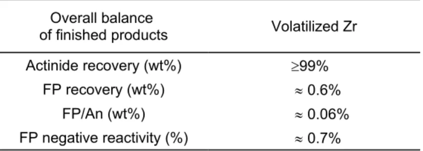
The results (see table I) indicate that it is theoretically possible to obtain a satisfactory recovery yield (excluding head-end losses during the mechanical operations) but that significant quantities of fission products—mainly zirconium—is entrained with the finished products.
Given our currently incomplete knowledge of all the steps in the proposed process, we have been obliged to adopt several hypotheses in simulating the process; the hypotheses that could significantly impact process performance are discussed below.
• The stripping yield was assumed equal to 94%. This figure is based on a single unoptimized exploratory experiment, and our experience with this step is insufficient to assert that this is the definitive figure.
• We have assumed that the zirconium was eliminated either by volatilization of zirconium tetrafluoride during the process head-end step, or when the actinides are
recovered from the aluminum metal phase by hydrochlorination of Al to AlCl3,
during which ZrCl4 could be separated from the AlCl3.
Table I : Overall balance of finished products Overall balance
of finished products Volatilized Zr
Actinide recovery (wt%) ³99%
FP recovery (wt%) » 0.6%
FP/An (wt%) » 0.06%
FP negative reactivity (%) » 0.7%
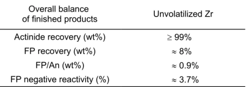
If this were not the case, the FP decontamination performance could be altered as indicated in following table:
Table II: Overall balance of finished products (unvolatilized Zr) Overall balance
of finished products Unvolatilized Zr
Actinide recovery (wt%) ³ 99%
FP recovery (wt%) » 8%
FP/An (wt%) » 0.9%
FP negative reactivity (%) » 3.7%
This would be near the upper permissible limit for FP contamination.
WASTE FLOW MANAGEMENT
Recycling the salt and metal phases may be advantageous for minimizing the waste flows [1]. However, both reductive extraction and oxidizing stripping involve the transfer of the reducing or oxidizing agent from one phase to the other, thereby modifying the composition of each phase; recycling the phases would thus require online adjustments to maintain a constant composition and holdup in the loops. This generates secondary waste flows representing sources of actinide leakage and FP discharge. The nature and volume of the waste flows are examined in the following sections.
Fluoride salt flow
Recycling the salt phase generally minimizes the waste flows. To prevent excessive accumulation of fission products in the salt which could jeopardize FP/An decontamination factor it must be decontaminated by extracting the fission products. For this purpose two routes can be considered:
• The chemical one by extracting all the radionuclides except the alkaline earths using Al/Bi alloys.
• The physical one by distillation under vacuum.
Extraction with Al/Bi alloy
The loop behavior was simulated, and three aspects were considered:
• once-through operation (100% drawoff) without decontamination, • loop operation (20% drawoff) without decontamination,
• loop operation (10% drawoff) with decontamination.
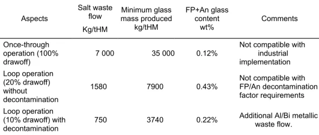
The results of waste flow assessment are summarized and discussed in Table III
The fluoride salt flow containing FP, and traces of actinides is not an acceptable ultimate wasteform, and must be conditioned in a glass matrix, which is very well known and has been used industrially since 1978. Preliminary study showed that glass matrix could accommodate up to 15-20wt% of fluoride salt.
Table III : waste flow assessment Aspects Salt waste flow Kg/tHM Minimum glass mass produced kg/tHM FP+An glass content wt% Comments Once-through operation (100% drawoff) 7 000 35 000 0.12%
Not compatible with industrial implementation Loop operation (20% drawoff) without decontamination 1580 7900 0.43%
Not compatible with FP/An decontamination factor requirements Loop operation
(10% drawoff) with
decontamination 750 3740 0.22%
Additional Al/Bi metallic waste flow.
The limiting parameter for glass is the maximum fluoride salt mass. Assuming a maximum fluoride content of 20 wt%, the glass quantity produced would be about 35 000 kg/tons with a FP +actinide content of about 0.12% for the once-through aspect and about 3740 kg/tons with a FP +actinide content of about 0.22% for the loop operation with decontamination aspect.
This last glass flow represents about 4300 kg of glass per Twhe with loop operation management (10% drawoff) with decontamination.
This is a major flow compared with the glass flow produced by PUREX reprocessing (about 800 kg/Twe.h). This aspect is a major weakness in the process and must be improved.
Distillation under vacuum
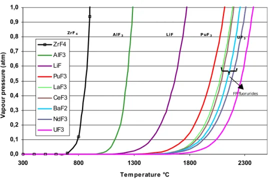
Ideally, the FP would be separated from the salt bath and recovered in oxide form, then vitrified, leaving a decontaminated salt bath. However, it could be very difficult or even impossible to selectively extract the alkali and alkaline earth FP from the salt bath. One possibility for separating them might be based on the differences in the boiling temperatures of the different fluorides.
Plotting the calculated vapor pressure values1 for the fluorides versus the temperature suggests
that there might in fact be a possibility:
1 Calculated from thermodynamic data using HSC Chemistry software version 4.1 from Outokumpu Research Oy.
C ompared fluorides vapour pressure = f(T) 0,0 0,1 0,2 0,3 0,4 0,5 0,6 0,7 0,8 0,9 1,0 300 800 1300 1800 2300 Temperature °C V ap o u r p re ss u re ( at m ) ZrF4 AlF3 LiF PuF3 LaF3 CeF3 BaF2 NdF3 UF3 ZrF4 AlF3 LiF P uF3 UF3 FP fluorurides
Figure 2 Fluoride vapor pressure versus temperature.
• Following the extraction step, the main salt components AlF3 and LiF could possibly
be distilled without affecting the fission product fluorides, which could be vitrified separately resulting in a smaller glass production than if the salt were conditioned as well. The decontaminated salt without FP could then be recycled in the process head-end.
• A rich AlF3 flow could possibly be separated; a fraction of this flow, estimated at
about 600 kg/tHM should be drawn off to adjust the AlF3 concentration in the salt.
The AlF3 drawoff could either constitute a waste salt (preferably lightly
contaminated) or be recycled as aluminum and then converted to a chloride (AlCl3)
for use as the oxidizing agent in the oxidizing stripping step. Recycling AlF3 as AlCl3
would make the process more complex and must be weighed against the drawback of
managing a lightly contaminated AlF3 waste flow. As no evaporation test has been
carried out under realistic conditions, it is impossible to estimate the residual FP contamination level in the salt.
If the potential for fractional distillation of the salt is confirmed experimentally, the ultimate glass waste flow arising from the salt loop would be significantly reduced. The glass mass produced (460 kg/tHM) would then be comparable to the quantity generated by a hydrometallurgical process for the same type of fuel.
The investigation of these routes should be a medium-term focus of research for the reductive extraction process.
Three other waste flows must be considered for the variant flowsheet: the noble metal containment matrix, the Al/Cu drawoff and the chloride salt drawoff.
Metal matrix for immobilizing the platinum group + Mo
An exploratory R&D program is now in progress to select more promising matrices. Although the studies have not been completed, we have nevertheless estimated the waste mass produced assuming 10 wt% waste loading—a minimum value that appears to be accessible based on the work done to date.
With this hypothesis the mass flow of metal waste immobilizing the platinum group + Mo would be about 280 kg/tHM.
Al/Cu flow management
Part of the Al/Cu flow must be drawn off to adjust the aluminum composition in the loop and
prevent any accumulation of copper from the oxidizing stripping step using CuCl2. This flow is
estimated at about 860 kg /tHM based on simulations using a model of the process, and could constitute the main source of actinide losses to the waste.
Prospects for improvement of metal flow management
AlCl3 could be used as the oxidizing agent instead of CuCl2 for the oxidizing stripping step. In
this case, the quantity of aluminum transferred into the metal phase by reducing AlCl3 would
correspond exactly to the quantity of aluminum transferred into the salt phase during the reductive extraction step; the composition of the metal phase would remain unchanged with no need for adjustment by drawing off the fluoride.
AlCl3 is a gas at the working temperatures imposed by Al/Cu alloy, i.e. about 670°C (or 100°C
above the alloy melting temperature). This issue must be taken into account in implementing this step and in the equipment design. Nevertheless, this difficulty should not be impossible to overcome.
Chloride salt flow
This secondary waste flow arises mainly from the fact that oxide precipitation by carbonates adds K and Li cations to the process, increasing the chloride salt inventory. The excess salt must then be eliminated.
Prospects for improvement of chloride salt flow management
Two routes could be investigated to avoid managing a secondary waste flow consisting of chloride salt:
• Distill the quantity of LiCl/KCl salt necessary to compensate for the additional carbonates. The distilled salt should be sufficiently decontaminated to make it acceptable for surface disposal.
• Supply the oxygen necessary to precipitate the oxides using a gaseous reactant that does not add any cation to the salt. This route avoids managing a secondary waste flow consisting of chloride salt. This issue will be addressed by a research program.
Overall waste flow assessment
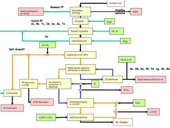
The waste quantities produced by reprocessing GEN IV carbide fuel have been evaluated. The values were calculated for two process variants. The first calculations, have been done with the initial process diagram (Figure 3).
Carbide Fuel Decladding
Grinding
Gaseous FP
Noble metals reductive extraction in Zn/Ni/Cu An reductive extraction in aluminium Dissolution in LiF-AlF3 Oxidizing stripping in LiCl-KCl Zn distillation AnO2 precipitation Volatil FP Cs, Rb, Tc, Cd, As, Se, Te Thermal treatment Hydrofluoration An Oxides Cladding material Sn HF(g) Ni/Cu or Al H2, Ar CuCl2 vitrified waste Waste packaging to be define
Noble metals in Ni/Cu or Al
Vitrification
waste
Ge, Nb, Ru, Rh, Pd, Ag, Sb, Mo
K2CO3 Li2CO3 LiF AlF3 Al/Cu Al LiCl KCl FP extraction in Al/Bi
Al/Bi alloy waste
Salt drawoff O2(g) Oxidation Carbide Fuel Decladding Grinding Gaseous FP
Noble metals reductive extraction in Zn/Ni/Cu An reductive extraction in aluminium Dissolution in LiF-AlF3 Oxidizing stripping in LiCl-KCl Zn distillation AnO2 precipitation Volatil FP Cs, Rb, Tc, Cd, As, Se, Te Thermal treatment Hydrofluoration An Oxides Cladding material Sn HF(g) Ni/Cu or Al H2, Ar CuCl2 vitrified waste Waste packaging to be define
Noble metals in Ni/Cu or Al
Vitrification
waste
Ge, Nb, Ru, Rh, Pd, Ag, Sb, Mo
K2CO3 Li2CO3 LiF AlF3 Al/Cu Al LiCl KCl FP extraction in Al/Bi
Al/Bi alloy waste
Salt drawoff
O2(g) Oxidation
Figure 3 : Initial block diagram
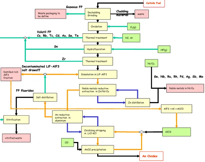
In a final calculation we assumed that the potential improvements described in the preceding paragraphs were feasible and had been applied (Figure 4). The result thus gives the minimum waste flow that can be expected in the present state of knowledge.
For the process head-end, fluoride salt is initially counted as primary waste; it is then assumed to be incorporated in a glass matrix as an ultimate wasteform. During this operation, the FP volatilized during the head-end heat treatment are incorporated in this flow without affecting the quantity of glass.
All the calculations were carried out on the basis of the material flows produced by reprocessing of one metric ton of heavy metal (black figures). In order to facilitate results inter comparisons,
other figure is given, the flows normalized to the production of 1 Tweh (red figures in bold).
Carbide Fuel
Decladding Grinding Gaseous FP
Noble metals reductive extraction in Zn/Ni/Cu An reductive extraction in aluminium Dissolution in LiF-AlF3 Oxidizing stripping in LiCl-KCl Zn distillation AnO2 precipitation Volatil FP
Cs, Rb, Tc, Cd, As, Se, Te Thermal treatment
Hydrofluoration An Oxides Sn HF(g) Ni/Cu H2, Ar AlCl3 Salt distillation FP fluorides Decontaminated LiF-AlF3 salt drawoff vitrified waste Distilled rich AlF3 fraction Waste packaging to be define
Noble metals in Ni/Cu
Vitrification
Ge, Nb, Ru, Rh, Pd, Ag, Sb, Mo
O2-Zr
Thermal treatment
AlF3 =>Al =>AlCl3 Cladding material waste O2(g) Oxidation Carbide Fuel Decladding Grinding Gaseous FP
Noble metals reductive extraction in Zn/Ni/Cu An reductive extraction in aluminium Dissolution in LiF-AlF3 Oxidizing stripping in LiCl-KCl Zn distillation AnO2 precipitation Volatil FP
Cs, Rb, Tc, Cd, As, Se, Te Thermal treatment
Hydrofluoration An Oxides Sn HF(g) Ni/Cu H2, Ar AlCl3 Salt distillation FP fluorides Decontaminated LiF-AlF3 salt drawoff vitrified waste Distilled rich AlF3 fraction Waste packaging to be define
Noble metals in Ni/Cu
Vitrification
Ge, Nb, Ru, Rh, Pd, Ag, Sb, Mo
O2-Zr
Thermal treatment
AlF3 =>Al =>AlCl3 Cladding
material waste O2(g)
Oxidation
Table IV: Waste flow assessment (initial scheme)
Process version Initial Scheme
Wasteform Al/Bi Glass Nickel/coppermatrix Al/Cu alloy Chloride salt Main
radionuclides
FP FP Platinum-group
metals
Actinide
losses Low actinide activity Mass produced kg/tHM Kg/Tweh 165 190 3750 4250 280 320 860 975 700 790 The last table shows that both the quantity and the number of waste flows produced by the reductive extraction process can potentially be reduced by a significant amount.
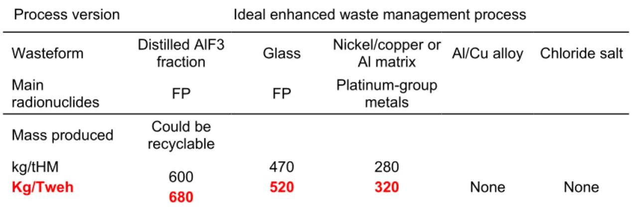
Table V: Waste flow assessment (ideal scheme) Process version Ideal enhanced waste management process
Wasteform Distilled AlF3fraction Glass Nickel/copper orAl matrix Al/Cu alloy Chloride salt Main
radionuclides FP FP
Platinum-group metals Mass produced recyclableCould be
kg/tHM Kg/Tweh 600 680 470 520 280 320 None None
Ideally, the process would generate only two types of high-level waste—glass and metal— together with a low-level salt waste (it is too early to quantify the waste radioactive contamination level) that could be recycled in the process.
CONCLUSION
The study shows that primary waste management must be improved since the expected process flows—especially the fluoride salt—are too large, but promising options exist and will be investigated.
Starting from the initial block diagram devised two years ago, the paper shows how process integration studies were able to propose process fittings which lead to a reduction of the waste variety and flows leading at an “ideal” new block diagram allowing internal solvent recycling, and self eliminating reactants. This new flowsheet minimizes the quantity of inactive inlet flows that would have inevitably to be incorporated in a final wasteform. The study identifies all knowledge gaps to be filled and suggest some possible R & D issues to confirm or infirm the feasibility of the proposed process fittings.
REFERENCES
1. Pyrometallurgical Processing Research Programme “PYROREP” contract N° FIKW-CT-2000-00049 Project N° FIS-1999-00199 Deliverables D21 “Technical-economical preliminary assessment”, D22 “System Studies: methodology”, D23 “System Studies: assessment of salt/metal reductive extraction process”.
2. Keurtz, R., Kuhrt, W., Massone, J., “Hydrofluorination of U/Th oxides and carbides with coating of pyrocarbon/silicon carbide pyrocarbon in the context of dry reprocessing of nuclear fuels containing thorium” Kerntechnik 13 (1971) pp 441-444. 3. Jouault, C. “Séparation pyrochimique d’éléments facilement réductibles contenus dans
des déchets nucléaires”, PhD thesis, INPG (2000).
4. Horie, M., Miyake, C., “Study of processing HLLW by super high temperature method, Recod’94 (1994).
5. Osipenko, A.G. et al. “Conversion of weapon-grade plutonium into nuclear MOX fuel
by pyrochemical methods” 5th International Symposium on molten salt chemistry and
technology, Dresde, Germany (1997).
6. Lacquement, J., Adnet, J.M., Brossard, P., Osipenko, A.G., Bychkov, A.V., Skiba, O.V., “Pyrochemical conversion of weapon-grade plutonium into plutonium oxide” Atalante 2000 (2000)
7. Grjotheim, K., Krohn, G. et al., Aluminium Electrolysis Fundamentals of the