Microfabricated Sensors for Medical Applications
Ben Kloeck, Nicolaas F. de Rooij
Institute of Microtechnology, University of NeuchäteK
2000 Neuchätel, Switzerland
1. Inlrochiclion
Mainly bccausc of ihcir sizc, a typical applicalion fiele! for inlcgralcd scnsors is ihc biomcdical world. and morc prcciscly ihc in-vivo dcicrminalion of physical and physiological paramclcrs. One important paramclcr is ihc prcssurc of body fluids. Piczorcsislivc prcssuro scnsors »rc chcap to fabricatc in mass and casy lo rcad-out. Morcovcr ihc dimcnsions of piczorcsislivc scnsors can bc madc vcry small. Thcrcforc, ihc fulurc of piczorcsisilvc prcssurc scnsors is in chcap disposablc calhclcrs for invasivc mcasurcmcnU wilh cxlcmal powcr supply. The r st scclion of ihis papcr shows how such a prcssurc scnsor can bc applicd for lhal purposc by mounling il in a 6F hcart caüiclcr.
Two morc applicalions arc prcscnlcd conccrning calhclcrs lhal conlain prcssurc scnsor chips which arc bascd on ihc icchnology dcvclopcd al ihc Inslilulc of Microlcchnology. The firsl is an 8P doublc-Iumcnl calhclcr for ihc invcsligalion of ihc csophagcal funclion. ncw scnsor chip was dcsigncd for ihis applicalion, using a doublc-sidc tnlcgralion icchniquc spccially dcvclopcd for ihis purposc. and ihc back-sidc contacl icchnology. Il consisls of a prcssurc scnsing pari and a pH scnsing pari. Thc advanlagcs of ihc scnsor dcsign wilh back-sidc conlacls arc out l in cd. In-vitro and prcliminary in-vivo cxpcrimcnls arc prcscnlcd, which show saiisfaclory rcsults for simullancous prcssurc and pH mcasurcmcnU. Thc sccond cxamplc is a 4P musclc calhclcr. dcvelopcd lo mcasurc prcssurcs and forccs in ihc musclc lissuc. Hcrc ihc spccial fcalurc is üic vcry small blcral dimcnsion of ihc scnsor chip.
Anolhcr arc a whcrc microfabricaüon of scnsors can bc succcssfully uscd for applicalions in ihc biomcdical ficld is lhal of clicmical scnsors.
Thc fabricalion icchnology for backsidc conlacicd ISPETs, similar lo lhal uscd in ihc combincd pH-prcssurc scnsor, will bc discusscd in morc dclail. micromachincd flow ccll for mulli-ion scnsing will bc prcscnlcd. Tlic fabricalion of ihis dcvicc is bascd on CMOS icchnology, combincd wilh anodic bonding of machincd glass äs well äs dcposilion on ion-sclcctivc polyincric incinbrancs. Pinally. ihc fabricalion, characlcrisücs and applicalion of a planar ampcromclric glucosc microclcclrodc will bc discusscd.
2. Prcssurc scnsor for hcart cathcthcr
Classical hcart calhclcrs arc csscntially lubcs fillcd wilh a physiological solulion lhal is in conlacl wilh ihc blood ihrough a flexible mcmbranc in ihc cathctcr lip. The prcssurc is mcasurcd cxicrnally al ihe olhcr cnd of ihc calhclcr. This syslcm works well for slatic prcssurcs, bul fast prcssurc changcs arc dampcd by ihc pliancy of ihc calhclcr walls. Evidcnlly, ihis problcm docs nol occur if Ihc prcssurc is mcasurcd and t ran s form cd lo an clcclrical signal, dirccüy in ihc cathclcr lip [1-5J.
Thc prcssurc scnsor prcscnlcd in ihis work was mounlcd in a 6P cathclcr (2 mm outcr diamclcr) by Keller AG für Druckmcsslcchnik (Winicrthur). Thc calhclcr lip was madc of slainlcsi slccl and ihc lubc of po)yurclhanc.The piczorcsislon arc lumcd loward ihc üisidc of ihc calhclcr. and only ihc mcmbranc cavily is cxposcd lo ihc ex t c mal cnvironmcnt.
Tlic calhclcr has bccn icslcd in-vilro. dry and in physiological iah soluiions. Thc »labUity was provcn lo bc saiisfaciory; Icsi lhan l mbar drifl in 42 hours, So for ihc calhclcr has nol bccn uscd for in-vivo cxpcrimcnli.
3. pll-nrcssnrc scnsor fo 3.1 Introduclion
Al prcscnl. csophagcal cathctcrs only allow ihc mcasurcmcnl of cilhcr pH (acidity) or prcssurc scparatcly. Por somc sludics and diagnoscs howcvcr, ihc mcasurcmcnl of both simullancously is feil äs a nccd lo obtain a morc complcic imagc of thc pysiological phcnomcna involvcd [6-8J. One importanl applicalion is ihc invcsligation of thc lowcr csophagcal sphinclcr (ihc ring-shapcd musclc lhat by conlraclion closcs ihc acccss lo ihc stomach). and in panicular ihc rcflux of slomach acid into ihc csophagus thai occurs if Ihis musclc is malfunclioning. Diagnosis is complicaicd by ihc faci lhal ihc Symptoms arc oftcn i nie rm tuen t and arc triggcrcd by Stimuli likc sircss or icmparalurc extremes. Anolhcr intcrcsting applicalion for mcdical and pharmacological rcscarch is thc dynamic and chcmical aclivily of ccrtain mcdicincs and drugs. Thc advaniagc of having a prcssurc scnsor al ihc samc limc is that also informaiions aboul üic movcmcnl of ihc csophagcal iracl arc obtaincd. Today's commcrcially availablc csophagcal cathctcrs for pH monitoring usc cithcr antimony or glass clccirodcs. Antimony clcctrodcs havc Ihc advanlagcs lliai ihcy arc small and vcry chcap. and Ihus suilcd for disposablc usc. On ihc olhcr hand. howcvcr, ihcy arc incxacl and suffcr from agcing and hystcrcsis, sincc ihc i r clcclrodc rcaclion is csscniially a corrosion proccss. Morcovcr. at Iow pH valucs ihcrc is an accumulalion of rcaction products around Ihc clcclrodc, which causcs falsc pH rcadings. Glass clccirodcs arc cxacl lo a icnth of a pH or bette r, and stablc. Thc disadvanügcs arc lhal ihcy arc fragile and lhal ihcy havc a high impcdancc. Süll, for Üic momcnl Üic glass clccirodcs arc üic mosl rcliablc dcviccs lhat arc on ihc market, but if ihcy havc lo bc combincd wilh prcssurc scnsors. ihcir sizc incrcascs, causing Ihus a lot of discomfort for ihc palicnl who rcccivcs Üic cathclcr ihrough his nosc. Comparcd wilh Üicsc cxisting Systems, ihc silicon bascd scnsor has üic advanlagcs of small dimcnsions, good accuracy and stability. and abovc all, a vast flcxibilily lo inicgratc two or morc scnsors on onc chip and on morc silcs in ihc cathclcr. In ihis scclion. a silicon bascd pll-prcssurc cathctcr (doublc-lumcn). wilh ihc possibility for ihc Integration of a rcfcrcncc clcclrodc in onc luincn. is discusscd. 19,101.
3.2 Sensor chin fabrication
Tlic scnsor chips arc fabricalcd by Standard microclcctronic »nd micromachining proccsscs on doublc-sidc polishcd, 3 inch wafcrs (boron-dopcd. 3-5 . 380 ihick). vcry spcoial f<xiturc of Ihis chip is lhal componcnis arc intcgratcd on boih sidcs. This is bccausc onc of ihc major dcsign goali was lo locatc all ihc coniaci pads on ihc back sidc of ihc chip. sincc U has lo bc mounicd in i cathctcr. Thcrcforc Üic prcssurc scnsor is intcgratcd on üic back sidc and Üic pH ISPliT, which musl bc cxposcd lo ihc solulion, on ihc fronl sidc, bul wilh conlacl fccd-ihroughs ihrough ihc chip. äs is shown schcmaücally in Pig. 1. Thc dimcnsions of üic chip »rc 1.5 mm by 4.0 mm.
Fig. 1: Transparent s eherne of ihe combined pH-pressure sensor The pressure sensor consisu of four boron-diffused piezorcsislors at the edges of a ihm membrane and connected in a Wheatstone bridge configuration. The outpul voliage is proportional to ihe pressure difference across Ihe membrane and to ihe applied bridge voliage. The membrane is etched in potassiuxn hydroxide from Ihe froni side of the wafer and iu thickness ii conlrolled by a four-elecirode electrochemical etch-siop. A 10 um ihick epilaxial layer of n-type silicon is grown on a p-type süicon subslraie. The p-type Substrate is eiched and etching is stopped al the epi-layer/subsiraie junclion by applying a passivaiing potential lo ihe epi-layer. The thickness of ihe remaining silicon membrane is thus defined exacüy by the thickness of ihe epitaxial layer and not influenced by the laper of ihe wafer.
The -ISFET fabricaüon resembles the sundard fabricalion process (11] wiih one exceplion, i.e. the location of ihe drain and, source conucts. Under ihe source and drain regions. holes are etched from ihe back side of ihe wafer, leaving a membrane of aboul 10 um ihick. A high phosphorous diffusion through this membrane. covered with aluminium establishes the electrical contacts to the source and drain from the back side of the chip. The process will be discussed in morc detail in seclion 5.
3.3 Caiheter encapsulation
The pH-pressure chip is mounted in a double lumen 8F catheter (2.7 mm diameter). Fig. 2 shows the imporunt advantage of the back· side contacts: this approach allows the sensitive pari to be almost al the same level äs ihe ouiside surfacc of ihe catheter, avoiding thus the presence of a cavity in the tip, where local pH could differ from the effective pH in ihe slomach. The gale of the pH sensor and ihe back side of ihe pressure membrane are directly in contact with the solulion. The catheier contains seven wires to contact the pressure sensor, iwo for ihe pH ISFET and one for possible Integration of an Ag/AgCl reference elecirode in ihe second lumen. The chips were mounted in ihe catheter by Keller AG für Druckmesstechnik (Wintenhur).
Fig. 2: Cross-section of the catheter tip, showing ihe chip encapsulalion
3.4 Measuremeni set-up
For the in-vitro measurements the catheier was inserted in a vertical flexible tube lhai was conseculively filled with differenl pH buffer solulion s. The upper liquid level was varied lo yield pressure variations in the order of 100 mbar. Thus pressure and pH could be measured simultaneously. Merck pH buffer Solutions were used. The pH was measured with an in-house built ISFET ampUfien a feedback control syslem lhai applies a constant VDS, measures IQ§ and
adjusts VGS through an Ag/AgCl rcference eledrode, in order to keep
ihis Ips constant. VQJ is then proportional to ihe pH of ihe
soluiion. The prenure wa· m ea u red with a Wheatitone bridge amplifier lupplied by Keller AO.
For the in -vivo measuremenu only battery powered equipment wai used. A portable in-houte built ISFET amplifler with skin reference electrode, a Keller DPM 80 Wheatitone bridge amplifier and MIC GaitrograpHs to obtain digiul recordings of the meaiurementi, The icnson were routinely calibrated before use.
3.5 Bcyulta and discunion
In-vilro measuremenis have shown that the pressure sensor had good lineariiy and a sensilivity of 8 mV/Vbar. The pH senior had a •ensitiviiy Of 56 mV/pH and a slabilily betler ihen 0.2 mV/h. Preliminary in -vivo measuremenu were canried out at the Insel Spital in Bern, in the stomach of a normal volunieer. A typical simultaneous recording of pressure and pH is shown in Fig. 3. At the same lime a glass pH -electrode (Ingold) was inserted in the stomach and the readings were observed to be parallel, with only slight difference t between both elecirodes caused by their different Position in the stomach. One of the advantages of ihe pressure recording is that the momenl when the catheier passes through the sphincter can be deiermined exacily.
Fig. 3: Simultaneous recording of pressure and pH in ihe stomach of a normal volunteer
3.6 Conclusion
The in-vitro characterisiics of ihe pH-pressure sensor are comparable lo equivalent single transducers. The Integration of pH and pressure sensors on one chip with back-s ide contacts enables an easy catheter mounting and adequate encapsulalion. To obtain better spatial Information, more measuring sites in the catheter are feasible. The Integration of a reference electrode has been tested in vitro. The first in-vivo tests with skin electrodes showed a good response for both pH and pressure recordings.
4. Force sensor for muscle catheter 4.1 Introduction
The activiiiy of muscles can be investigated by inserting a thin catheter Ion g i lud in all y into ihe muscle bündle, force sensor in ihe side-wall of ihe catheter gives Information on the lateral action of the muscle. A sensor chip was designed to replace an older System where minuscule strain gauges were glued on a beam. Its fabricaüon involved individual assembling of each sensor and laborious handling of the microscopic parts. Evidently this applicalion is a lypical ch all enge for inlegraied sensor lechnology. This seclion presenls a first generalion of this type of senson, lo show the feasibility of fabricating silicon integrated force sensors with very small lateral dimensions.
4.2 Chip fabricalion
The chip had lo be designed lo be mounied in a 4F catheter (1.3 mm outer diameter). Its dimensions were limited al maxiumum 0.6 mm witdth and 6 mm length. A mesa was required on one end of the chip, lo touch Ihe thin membrane in the catheier opening. äs shown schematicaUy in Fig. 4. The chip thickness was 0.2 mm, and ihe total ihickness of ihe chip and the mesa was 0.4 mm. The operational ränge was 40 mN and ihe maximum allowed deflection of the beam 0.05 mm. If ihe beam deflects too much, then the muscle tissue presses on ihe border of ihe catheter opening, and not on the mesa anymore. To increase the force sensilivity, a cavity was eiched
24
under the resiitors. It i· easily calculated thtt ihe icnsi vity U proportional to the invene of the square of ihe remaining thicknes i. The only rettriction is the deflec on at maximum force. It wai calculaled that · thickne» of 100 μπι would give a beam defleclion at 40 mN ofleu ihan 50 μιη.
Fig. 4: Cross-section of the force sensor and the catheter encapsulation
The icnson were fabricated on three-inch phosphorous doped lilicon wafera of (100) orieniation. The nominal thickness was 381 jim and the resistivity 1-10 Ω cm. The fabrication sequence was s nilar to that of the prrssure senson, with the exception of the doping concentralion of the piezoresistors. Since no Wheatstone bridge configuration was used for these sensors, ihe doping concentration was chosen high, 2 χ 10^°cm"3 at the surface. in order to reduce the lemperature dependence of the piezoresistance cocfficicnts. The sheet resislivity was 20 Ω per square. After fabrication of the piezoresistors. the wafers were etched in 40 % poussium hydroxide at 60°C, to obiain the chip profile that is illustrated in Fig. 4. The etching was done in two Steps: first the aforementioned cavity was etched, and then the oxide mask was removed. except on the mesas, to ctch the chip to the required thickness of 200 μπι. Finally the wafes were diced into individual senson. Fig. 5 shows the design of two sensor types that were realized; one was 0.6 mm wide and the second only 0.3 mm.
4.3 Mffl
For in-vitro measurcment, the sensors were glued on a PCB in a way that allowed ver cal deflcction of the beam. A special measurement sct-up was developed to measure simultaneously the force applied on the m«a, the deflection of the beam and ihe resistor change. For this purpose, an I-DIM displacement sensor (Cary Compar, Le Locle) was mounied vertically on a support. In the sensor head, an inductive Stylus was suspended on two horizontal spring blades with a precisely known spring constant. The I-DIM head could move veiticaliy. and a second displacement sensor allowed to measure its movement. When ihe Stylus just touched ihe beam. the applied force was zero and the reading of ihe displacement of the Stylus (caused by its own weigth) was sei to zero. When the I-DIM head was moved down, the applied force and the Stylus displacement were read from ihe display. The defleclion of the beam was the difference of ihe readings of ihe I-DIM and the second displacement sensor. In this way increasing forces were applied and ihe corresponding resislance changes and deflections were measured.
For ihe lempcraiure characlerization, ihe PCB-mounted force sensort were placed in a fumace. The sensitivity was measured by a two-poinl calibration, using a known weighL
4-4 Resulu and discus«ify
This paragraph summarizes ihe resulu of ihe meaniremems on four sensors. No functional differcnces were observed between ihe iwo sensor type· (0.6 mm and 0.3 mm). Fig. 6 shows a typical recording of Ihe resistance change and ihe deneclion of ihe beam s a function of applied force. The seniilivity was 0.5 Ω/ΚΩ mN. For a r nge of 40 mN, this results in a f ll scale resisiance change of 20 ΩΑΩ. The defleclion ai 40 mN was 34 μπι, which is within ihe required specificalion limil of 50 μπι. It is noted lhai ihe sensitivity could be increased by lak ig a lower doping concentration for the resistors. For the used concentration the longitudinal piezoresistance coefficient in ihe <110> direction was SOxlO'11 Pa"*t s opposed lo e.g. SOxlO'11 Pa'1 for doping concentration of 10'1* cm'3. However. lhal would be ai ihe expense of a higher lempcraiure coefficient. In ihe inicrval from room lermperaiure lo 70°C. the lempera ire coefficienl of ihe rcsistor (TCR) was measured to be 1400 ppm/°C and of ihe sensitivity (TCS) 1700 ppnVC
Fig. 6: Resistance change ( ) and beam deflection ( ) s a function of applied force.
4.5 Conclusion
The chip presented in this section was mainly a feasibility study s a first slep lowards a more sophislicaied device. In particular temperature compensation was completely lacking on this chip. Because of the »nall dimensions (especially for the 0.3 mm chip), it is hardly possible to integrale Iwo supplementary transverse piezoresistors and build a Wheatstone bridge. A f ll bridge would require ihe two Iransverse resislors to be placed on one l ine and besides the longitudinal ones, in order to sense the samc mechanical tensions.
A valuable solution of this problem that requires only longitudinal resistors and still includes lemperature compensation is proposcd here. If two identical pairs of longitudinal resistors are integrated on both sides of the chip, s schematically shown in Fig. ?. »hen deflection of the chip causes ihe two resistors on one side to increase and ihe iwo on the other side lo decrease. As for the pressure sensors, the four resistors can be connected in a Whealslone bridge configuralion, and temperature changes will in first order be a common mode effect and will nol appear ai ihe differential output of the bridge. Using the double-side Integration and back-side contact lechnologies which were developed for the pH-pressure chip, such a force sensor can easily be fabricaied with very small lateral dimensions. To decrease the size of the contact feed-throughs, very thin wafers should be used (100 to 150 μπτ ihick).
Fig. 5: Two designs of ihe force iensor one wilh a chip width of 0.6 mm (upper), and one of 0.3 (lower)
Fig. 7: Design proposition for a very narrow force »en«or, uiing double-iide Integration and back-ud« coniacl
5. Microfabricaicd chemical »enion 5.1 pH-ISFETS
Ion-con cent rat ion or ion-activity sensori using field effect transistors are known since almost iweniy years and denoted s Ion-sensitive Field Effect Transistors or ISFETs. Despile thcir promising perspeciives, a number of problem s related to encapsulation and drift are still not solved and hamper a wide spread use. In order lo improve the encapeula on we developcd pH-ISFETs with back-side contacts. [12)
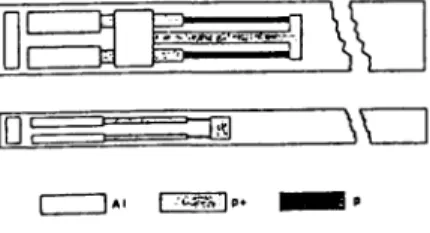
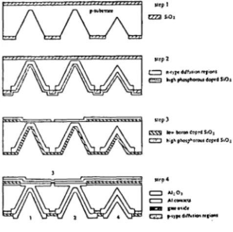
To fabricate feed-throughs in a s icon wafer, several techniques can be utilized. A raiher simple method which can be used on wafer level, is the anisotropic etching of the silicon Substrate wiih e.g. pocassium hydroxide to form holes in the Substrate leaving a thin membrane the thickness of which can be controlled. Elecirical contacts to the source and drain regions on the topside of the chip. can be made by dlffusion of dnin/source dopant ihrough this thin silicon membrane. On a double side polished wafer (p-rype 3-5 Ωαη, thickness 380 μτη) an oxide layer of about 1.5 μηι is grown s masking tayer for the potassium hydroxide etching. Then the openings for the drain and source back-side contacts are made. The holes in the silicon are etched in a 40 % potassium hydroxide solution at 60 °C The wafer is eiched uniil less than 10 μπι of silicon is left leaving a diaphragm of about 80 μηι χ 80 μιη at the bottom
f 1 n-Οϊ« difftiiion rrf ionl
k>fNphoiFtraraujdof«ISiOi
Fig. 9: Schemalic diagram of the CC^-iemor 5.2
MuJ
ι-ιοη sensorsIn order to realize FET-based sensors icnsitive to other ion s than H*-ions, polymeric membranes with ionophores can be applied. However, the fixation of this type of membranes lo the basic sensor structure is a problem. Glass encapsulations based on anodic bonding can solve both the problem of membrane fixation and packaging. The types of glass commonly used for this process are known to be highly resistanl against chemical attack. Prior to the bonding process, holes are drilled ihrough the glass in order to have access to the sensing area s well s to the electrical contacts. The glass hole provides excellenl physical fixation of the membrane. Additional treatment of the glass bcfore membrane deposition can further improve the adhesion of the membrane to the sensor [14]. The basic design of our structure u shown schematically in Fig. 10. It consists of a silicon Substrate into which a field effect transistor has been realized. The gate of the transistor consists of a s ver thin film, using a titantum adhesion layer. On top of the silicon Substrate, the glass plate is applied by anodic bonding on an intermedi re polysilicon layer. After the anodic bonding procedure. the silver layer (gate) is partially converted into a silverchloride layer in order to provide a stable electrochemical interface wiih the coverin g membrane.
Fig. 8: Fabrication sequence of back-side pH-ISFETs The back-side openings are now enlarged to enable the deposition of a phosphorous doped silicon oxide layer by chemical vapour deposition (CVD). After the diffusion of the phosphorous into the silicon all oxide layers are etched away and a boron doped silicon oxide layer is deposited on both sides of the wafer. Then the drain and source areas are opened and a phosphorous doped silicon oxide layer is grown (typically 900 A) and at the same time the drain and source areas are formed together with the channel stop at both sides of the wafer. Alumina is then deposited by CVD s pH-sensitive layer (600 A). After opening the contact Windows on the back-side. aJ um in i um contacts are formed by lift-off and the source and the Substrate are directly connected. Furthermore some MOSFETi are made for on wafer tecting. A diagram of the sensor fabrication is shown in Fig. 8.
The characteristics of the pH sensor are the following: drift less then 0.5 mV/h and pH sensitivity of about 56 mV/pH.
A carbon dioxide electrode based on the Severinghaus principle has been developed using the back-side contacted pH-ISFETs (Fig. 9). The ρΗ-ISFET is used s the intemal pH-sensing element and a temperature sensitive diode ii integrated on the same chip [13].
Fig. 10: Diagram of the glass-ericapsulited pH-sensitive ISFET 1) η-type Substrate. 2) contact pads, 3) p-well, 4) drain and source (n* type). 5) conductor (n-type) (forms diode with well) with at the end a Pi/Al electrode (black triangle connected during the anodic bonding with a metal layer to the gate). 6) gate area, exposed to the solution after the anodic bonding. 7) polysi con layer, 8) glass (only par y shown but covers completely the polysilicon layer
The sensitivity of these sensors to chloride ions was 58.5 ± l mV/pCl at 25 °C The observed drift was less then 10 μΥ per hour at 25 °C in a 0.1 M KC1 solution. The pH characteristics of a glass encapsulatcd ISFET without the Ag/AgCl gate is comparable to those mentioned above.
A flow-through cell based on the above described technology has been realized. It allows simultaneous measurement of H"*", K* and Ca++-ion activities [15] For the K+-ion activity and Ca++-ion
activity measurement solvent polymeric membranes are used. As reference electrode a pH-ISFET with a retarded pH-response was developed thereby creating the possibility to operate this ISFET s an ion-insensitive FET over short periods of lime (pseudo-REFET). The multi-ion sensor consisting of the ρΗ-ISFET, pK-ISFET and pCa-ISFET together with the pseudo-REFET showi a high precision in combination with a high-sample frequency.
The ccll, with an intern»! volume äs imall äs 12 , ii evaluated in conneclion with a FTAstar® flow injection analysis syslem. The system's pcrformance ii Ulustrated in Fig. 11. Into the carrier stream respeclively samplei of diffcrenl pH. diffferent pK and different pCa were injected. Subsequenüy, a sample was measured in which the conceniralion of all three species was changed. As can bee iccn from the widih of the pcaki, the response is very fast and up to al least 200 samples per hour can be analyzed. The «mall pll-pcaks at the injection of the higher cakium ion concentration are caused by an actual decrease in pH and not by inierference, and thus U can be concluded thal the cross-talk between the sensors is negligible.
Fig. II: Typical Output registration of the flow-through ccll in conneclion with an FIA System
5.3 Planar glucose sensor
An amperometric glucose sensor (dimensions: 0.8 mm by 3 mm) consisting of a planar three-electrode ccll, an enzyme membrane and an outer polyurethane membrane. has been developed in our laboratory [16.17].
The sensor is realized using ihin-film deposilion and lift-off techniques and consists of two Pt electrodes (working and counter) and an Ag/AgCl reference electrode. It is coupled with an immobilized glucose oxidase membrane and the amount of U2&2 produced is measured at 0.7 V. In order to render the sensor response less dependem of the dissolved oxygen concentration a polyurethane membrane is applied by dip-coating. The sensor response. measured at 37 "C in a Ringer solution (pH 7.5) a tu rat cd with 5 % (>2. U linear up to 40 mM glucose with a sensiüvity of 1.8 ± 0.2 nA/mM. The operational lifetime. deftned äs the period during which the sensitivity remains constant. is approximately one week. The storage lifetime is more than one month. Recently the lift-off technique has been used for patteming enzymatic membrane l on wafer level [18]. Sensors with on wafer deposited enzymatic membranes (without the polyurethaoe membrane) show a linear response to 1.5 mM glucose and respond to aboul 6 mM with a good uniformity amongst the sensors.
6. Conchmoni
Many classical Systems for medical diagnosis can be miniaturized effectively by the introduction of silicon integraled sensors. Moreover, the performance of the sensors is often better ihan that of the classical devicei, and even new possibilities are created. This has been shown in this paper by examples of sensors that were mounted in catheters for invasive use in the human body. Also with sensors for ex vivo use. such äs the multi-ion sensing flow through cell. the small dimension are of great advantage to minimize the sample volume.
7. Acltnowledgements
The author would like to thank his coworkers of the Microclectronici Sensor Technology Oroup of the Institute of Microtechnology of »he Univenity of Neuchltel äs well äs his colleagues of the Swiss Center for Electronics and Microtechnology Inc. (CSCM) for the many diicussions. deiigni, skillful fabrication and charactcrizalion of the sensors diicuued in this paper.
8. Reference^
[I] Samaun, K,D. Wise and J.D. Angel. An IC Piezoresistive Pressure Sensor for Biomedical Instrumentation. IEEE Transactions on Diomedical Engineering. BME-20 (2). pp., 101-109 (1973) 12] W.H.Ko, J.Hynecek and S.F. Boelcher. Development of
a Miniature Pressure Transducer for Biomedical Applications. IEEE Transactions on Electron Devices ED-26 (12 pp). 1869-1905 (1979)
D] M. Esashi. Fabrication of Catheter-Tip and Sidewall Miniature Pressure Sensors. IEEE Transactions on Electron Devices. ED-29 (1) pp. 57-63 (1982). [4] X.-P. Wu. M.-H. Bao and W.-X. Ding. An Integrated
Pressure Transducer for Biomedical Applications. Sensors and Actuators. 2 pp. 309-320 (1982). [5] J. Bryzck, R. Mayer and Ph. Barth, Disposable Blood
Pressure Sensors with Digital On-Chip Laser trimming. Technical Digest of the IEEE Solid-Siate Senior and Actuator Workshop. Hilton Head Island. Souih Carolina. June 1988, pp. 121-122.
[6) M.B. Orringer, R. Lee and H. Sloan. A combined manometric-pH recording caiheter for esophageal function tests, Ann. thoracic. Surg.. 26 p. 581 (1978). [7] P. Ask. G. Edwall and G. Tibbling. Combined pH and
pressure measurements for oesophageal investigations, Medical & Biological Engineering & Computing. 19 pp. 443-446 (1981).
[8J J.C-M. Hu an g and JCD. Wiie, A monoliihicc pressure-pH sensor for esophageal studies. International Electron Devices Meeting, Technical Digest. San Francisco, USA. pp. 316-319 (1982).
[9] B. Kloeck. H.H. Van den Vlekkert. N.F. de Rooij. M. Muntwyler and K. Anagnostopoulos, A Combined pH Pressure Caiheter for Gastro-Enterological Applications, Sensors and Actuators, 17, pp. 541-545 (1989)
[10] H.H. Van den Vlekkert, B. Koleck. D. Prongue. J. Bcnhoud. B. Hu. N.F. de Rooij, E. Gilli, Ph. de Crouzaz, A pH-ISFET and an integrated pH-pressure senior with back side conlacts. Sensors and Actuators, 14 pp, 165-176 (1988).
[111 P· Bergveld. N.F. de Rooij. Nederland Tijdschrift voor Natuurkunde. A 46-1 (1980)
[12] H.H. van den Vlekkert, Some fundamental and pracücal aspects of CHEMFETS, Ph..D. Thesis. Univenity of Neuchitel, Switzeriand, 1988.
[131 B. Hu. HH. van den Vlekkert, N.F. de Rooij, Carbon dioxide gas-sensing electrode based on a plMSFlTT wuh back-side contact. Sensors and Actuators, H (19S9) 275-278.
[14] Hans van den Vlekkert. Colin Francis, Alain Griscl, Nico de Rooij, Solvent Polymeric Membran«· combined with chemical Solid State Seniors, Analyst, LL2. (1988).
[15] H.H. van den Vlekkert, A. van den Berg, A. Gritel, NF, de Rooij, -Multi-ion seniing syitem baieJ on tlasi-encapsulated pH-ISFETs and a pseudo-REFET. Seniors and Actuators, Bl (1990) 39.MOO.
[16] S. Gemet. M. Koudelka. N.F. de Roog. Fabricaikw and characterisaüon of a planar electrochcmic*! cell and its application äs a glucose senior. Seniors annd Actuaton u (1989) 59-70.
(17) M. Kcudelk». S. Gern«!. N.P. d· Roo.J. PUnar •mpvrofnetnc enzyme-bated ftucut· microelecirtKk) Scnton and Actuaion 1L(I989) 157-165.
118) S. Genie«. M Kcmdelka. NF. de Rocij, A planar «lucoM cnrymc cJectroJe. Senior· «nd Actuatori jj_ B1989) 537.540.