HAL Id: tel-03231248
https://tel.archives-ouvertes.fr/tel-03231248
Submitted on 20 May 2021
HAL is a multi-disciplinary open access archive for the deposit and dissemination of sci-entific research documents, whether they are pub-lished or not. The documents may come from teaching and research institutions in France or abroad, or from public or private research centers.
L’archive ouverte pluridisciplinaire HAL, est destinée au dépôt et à la diffusion de documents scientifiques de niveau recherche, publiés ou non, émanant des établissements d’enseignement et de recherche français ou étrangers, des laboratoires publics ou privés.
ferromagnetic composites : Toward medical applications
Ziyin Xiang
To cite this version:
Ziyin Xiang. Enhancing low-frequency induction heating effect of ferromagnetic composites : Toward medical applications. Materials. Université de Lyon, 2021. English. �NNT : 2021LYSEI022�. �tel-03231248�
THESE de DOCTORAT DE L’UNIVERSITE DE LYON
opérée au sein de
L’Institut National des Sciences Appliquées de Lyon
Ecole Doctorale
N° ED160 EEAÉLECTRONIQUE, ÉLECTROTECHNIQUE, AUTOMATIQUE
Spécialité/ discipline de doctorat
:Génie électriqueSoutenue publiquement le 12/Avril/2021, par :
Ziyin XIANG
Enhancing Low-frequency Induction Heating
Effect
of Ferromagnetic Composites – toward Medical
Applications
Devant le jury composé de :
SEBALD Gaël Professeur des Universités/INSA-LYON/Université de Tohoku Examinateur GUIFFARD Benoit Professeur des Universités/Université de Nantes Rapporteur DEMOLY Frédéric HDR, Maître de Conférences /UTBM Rapporteur
NARITA Fumio Professeur /Université de Tohoku Examinateur DANIEL Laurent Professeur des Universités /Centrale Supelec Examinateur
SIGLE ECOLE DOCTORALE NOM ET COORDONNEES DU RESPONSABLE
CHIMIE CHIMIE DE LYON
http://www.edchimie-lyon.fr Sec. : Renée EL MELHEM Bât. Blaise PASCAL, 3e étage secretariat@edchimie-lyon.fr INSA : R. GOURDON
M. Stéphane DANIELE
Institut de recherches sur la catalyse et l’environnement de Lyon IRCELYON-UMR 5256
Équipe CDFA
2 Avenue Albert EINSTEIN 69 626 Villeurbanne CEDEX directeur@edchimie-lyon.fr E.E.A. ÉLECTRONIQUE, ÉLECTROTECHNIQUE, AUTOMATIQUE http://edeea.ec-lyon.fr Sec. : M.C. HAVGOUDOUKIAN ecole-doctorale.eea@ec-lyon.fr M. Gérard SCORLETTI
École Centrale de Lyon
36 Avenue Guy DE COLLONGUE 69 134 Écully
Tél : 04.72.18.60.97 Fax 04.78.43.37.17 gerard.scorletti@ec-lyon.fr
E2M2 ÉVOLUTION, ÉCOSYSTÈME,
MICROBIOLOGIE, MODÉLISATION
http://e2m2.universite-lyon.fr Sec. : Sylvie ROBERJOT Bât. Atrium, UCB Lyon 1 Tél : 04.72.44.83.62 INSA : H. CHARLES
secretariat.e2m2@univ-lyon1.fr
M. Philippe NORMAND
UMR 5557 Lab. d’Ecologie Microbienne Université Claude Bernard Lyon 1 Bâtiment Mendel 43, boulevard du 11 Novembre 1918 69 622 Villeurbanne CEDEX philippe.normand@univ-lyon1.fr EDISS INTERDISCIPLINAIRE SCIENCES-SANTÉ http://www.ediss-lyon.fr Sec. : Sylvie ROBERJOT Bât. Atrium, UCB Lyon 1 Tél : 04.72.44.83.62 INSA : M. LAGARDE
secretariat.ediss@univ-lyon1.fr
Mme Sylvie RICARD-BLUM
Institut de Chimie et Biochimie Moléculaires et Supramoléculaires (ICBMS) - UMR 5246 CNRS - Université Lyon 1
Bâtiment Curien - 3ème étage Nord 43 Boulevard du 11 novembre 1918 69622 Villeurbanne Cedex Tel : +33(0)4 72 44 82 32 sylvie.ricard-blum@univ-lyon1.fr INFOMATHS INFORMATIQUE ET MATHÉMATIQUES http://edinfomaths.universite-lyon.fr Sec. : Renée EL MELHEM
Bât. Blaise PASCAL, 3e étage Tél : 04.72.43.80.46
infomaths@univ-lyon1.fr
M. Hamamache KHEDDOUCI
Bât. Nautibus
43, Boulevard du 11 novembre 1918 69 622 Villeurbanne Cedex France Tel : 04.72.44.83.69
hamamache.kheddouci@univ-lyon1.fr
Matériaux MATÉRIAUX DE LYON
http://ed34.universite-lyon.fr Sec. : Stéphanie CAUVIN Tél : 04.72.43.71.70 Bât. Direction ed.materiaux@insa-lyon.fr M. Jean-Yves BUFFIÈRE INSA de Lyon MATEIS - Bât. Saint-Exupéry 7 Avenue Jean CAPELLE 69 621 Villeurbanne CEDEX
Tél : 04.72.43.71.70 Fax : 04.72.43.85.28 jean-yves.buffiere@insa-lyon.fr
MEGA MÉCANIQUE, ÉNERGÉTIQUE,
GÉNIE CIVIL, ACOUSTIQUE
http://edmega.universite-lyon.fr Sec. : Stéphanie CAUVIN Tél : 04.72.43.71.70 Bât. Direction mega@insa-lyon.fr M. Jocelyn BONJOUR INSA de Lyon Laboratoire CETHIL Bâtiment Sadi-Carnot 9, rue de la Physique 69 621 Villeurbanne CEDEX jocelyn.bonjour@insa-lyon.fr ScSo ScSo* http://ed483.univ-lyon2.fr Sec. : Véronique GUICHARD INSA : J.Y. TOUSSAINT Tél : 04.78.69.72.76 M. Christian MONTES Université Lyon 2 86 Rue Pasteur 69 365 Lyon CEDEX 07 christian.montes@univ-lyon2.fr
I would first like to thank my supervisor, Dr. Benjamin Ducharne, whose expertise is invaluable in formulating the research questions and methodology. He is always there waiting for helping me and answering me at any time. He is a patient, optimistic and responsible supervisor. He always encourages me with a smile and a sentence he used to say: “However, the good thing is…you have made progress!” when I encounter difficulties or make mistakes. Sometimes he is more like a kind friend.
I would like to express my great appreciation to my thesis co-supervisor Dr. Minh Quyen Le. She played a great role in promoting and supervising the completion of my thesis. She is a passionate and creative researcher. Her insightful guide pushed me to sharpen my thinking and brought my work to a higher level. I want to thank her for her patient support and for all of the opportunities I was given to further my thesis.
Besides my advisors, I would like to thank the rest of my thesis committee: Prof. Benoit Guiffard and Dr. Frédéric Demoly for their valuable comments on my thesis; Prof. Gaël Sebald, Prof. Fumio Narita, Prof. Laurent Daniel and Dr. DeLLA SCHIAVA Nellie for taking time reading my thesis and present on the defense, evaluating my work.
I wish to acknowledge my Ph.D. scholarship provided by the Chinese Scholarship Council (CSC), the UT-INSA program. Thank my country (China) for giving me this precious opportunity to study abroad.
My sincere thanks also go to Dr. Laurence Seveyrat, who has helped me a lot with SEM and DSC test with great patient. I am grateful for the assistance given by Dr. Pierre-Jean Cottinet for his help of establishing the LFIH experimental setup. I would like to thank Dr. Jean-Fabien Capsal for helping me with building the thermal transfer modeling in Comsol simulation. I want to thank Dr. Gildas Coativy, he provided me useful suggestions about polymer material at the beginning of my thesis. I whould also like to offer specially thanks to Dr. DELLA SCHIAVA Nellie for her valuable advices in medical applications. I appreciate a lot the experience in hospital where I had the opportunity to observe her performed varicose treatment on a patient.
I would also like to thank staffs and colleagues in LGEF laboratory, Mr. Frederic Deformerie: a skillful technician who always helping me cutting samples or sample holders. A big thanks to and Ms. Evelyne Dorieux: the most patient and responsible secretary I have ever known. My special thanks to Dr. Mickaël Lallart and Dr. Linjuan Yan, for providing me kindly help and useful information about future work.
who had been an internship student and worked with me for 6 months. And my special thanks to Mr. Van Cuong Nguyen for helping me with 3D printing stuff, we have done a lot of work together. My thanks also go to my sweet sisters Ms. Yan Zhang, Ms. Xiaoting Zhang, Ms. Kritsadi Thetpraphi and Ms. Yuanyuan Liu, for always sharing the ups and downs of life and work with each other. I wish to thank as well as Ms. Giulia Lombardi, Mr. Bhaawan Gupta, Ms. Hiba Haissoune, Mr. Omar Zahhaf, Ms. Giulia D'Ambrogio and Mr. Amaury Fimbelfor all the happiness and good memories we have been together.
I would also take this opportunity to thank my boyfriend Mr. Bo Chen, always stays with me, encourages me, and takes care of me.
At last, I sincerely thank my family, my parents and my brother, for being my spiritual support. Especially my mother, she is a good listener and always provides me with wise counsels. I really appreciate them for supporting all my decisions. No matter how far away, there is always a place in the deep of the heart, we call it home.
Ziyin XIANG 23/03/2021
Les composites ferromagnétiques, matrices polymères renforcées de particules ferromagnétiques présentent un potentiel intéressant dans de nombreuses applications médicales. Dans cette thèse, nous nous concentrons particulièrement autour du Chauffage par Induction Basse Fréquence (CIBF) de cathéters ferromagnétiques, une méthode alternative pour l'ablation des varices. L'effet CIBF apparaît dès lors que le composite est exposé à un champ magnétique alternatif. Ce phénomène est principalement dû aux courants de Foucault dits "microscopiques" générés par les mouvements des parois des domaines magnétiques. En introduisant le cathéter à travers la varice endommagée et en l'excitant par un champ magnétique basse fréquence, haute amplitude, il est concevable d'atteindre une température suffisamment élevée pour guérir correctement la zone endommagée sans perturber les zones saines environnantes. Par comparaison aux traitements existants, la méthode CIBF est précise, économique et simple. En transférant la chaleur sans conduction, l'encombrement du cathéter est réduit et le procédé semble applicable même pour des veines très sinueuses.
Des composites ferromagnétiques de différentes formes et fractions volumiques ont été fabriqués et testés grâce à un dispositif expérimental dédié. Différents paramètres (fréquence, pourcentage de particules…) ont été analysés afin d’établir la combinaison présentant la meilleure réponse thermique. Les propriétés physiques (perméabilité, conductivités électrique et thermique) ont également été caractérisées. Un modèle Comsol® combinant comportement ferromagnétique et thermique a été conçu afin d’améliorer la compréhension des phénomènes. Pour améliorer la conversion, des échantillons anisotropes ont été développés en imposant un champ magnétique statique dans la phase de solidification.
Finalement, une imprimante 3D de type extrusion a été utilisée pour imprimer des échantillons de formes proches de celle d’un cathéter. Des spécimens isotropes et anisotropes ont été imprimés. Les réponses CIBF distinctes et marquées entre les différentes directions testées chez les échantillons anisotropes ouvrent la voie à d’autres applications médicales comme le suivi électromagnétique (navigation chirurgicale).
Mots clés : Composites ferromagnétiques; Chauffage par induction basse fréquence (CIBF); Modélisation par transfert thermique; Composites à comportement magnétique anisotrope; La fabrication additive; Magnétophorèse; Applications médicales
Ferromagnetic composites, polymer matrix mixed with ferromagnetic particles show good potential in medical applications. In this thesis, we especially focus on the Low Frequency Induction Heating (LFIH) of ferromagnetic catheters as an alternative process for varicose veins ablation. The LFIH effect appears as soon as the composite is exposed to an alternating magnetic field. This phenomenon is mainly due to the so-called "microscopic" eddy currents generated by the magnetic domain wall motions. By inserting the catheter through a damaged varicose vein, and exciting it with a low frequency, high amplitude magnetic field, it is conceivable to reach a temperature high enough to properly heal the damaged area without injuring the surrounding healthy ones. Compared to the existing treatments, the LFIH method is accurate, cost competitive and simple. By transferring heat in a non-conductive way, the catheter bulkiness is reduced and the method is applicable even in tortuous veins.
Ferromagnetic composites with different shapes and particle volume fractions were built and tested in a specific experimental bench. Different parameters (frequency, particle fraction …) were analyzed to reach the best thermal answer. The physical properties (permeability, electrical and thermal conductivities) were also characterized. A Comsol® model combining ferromagnetic behavior and thermal transfer properties was designed to improve the understanding of the phenomena.
For a better efficiency, specimens with anisotropic magnetic behaviors were built by curing them under the influence of a static magnetic field.
Finally, a commercial extrusion-type 3D printer was used to print samples with catheter shapes. Isotropic and anisotropic specimens were built. Interesting LFIH behavior were observed and for the later ones directional answers potentially interesting in alternative medical applications like the electromagnetic tracking (surgery navigation).
Key words: Ferromagnetic composites; Low-frequency induction heating (LFIH); Thermal transfer modeling; Anisotropic magnetic behavior composites; Additive manufacturing; Magnetophoresis; Medical applications
ABS Acrylonitrile Butadiene Styrene
AM Additive Manufacturing
AMF Alternating Magnetic Field
CAD Computer Assitant Design
CAI Computer Assisted Interventions
DSC Differential Scanning Calorimetry
EMT Electromagnetic Tracking
EVSA Endovenous Steam Ablation
EVTA Endovenous Thermal Ablation
FCGW Ferromagnetic Composite Guide Wire
FDM Fused Deposition Modeling
GEM General Effective Media
IGT Image-Guided Therapy
IH Induction Heating
kRPM Kilo Revolution Per Minute
LFIH Low-Frequency Induction Heating
MFH Magnetic Fluid Hyperthermia
MHP Magnetic Heating Power
MRI Magnetic Resonance Imaging
PDMS PolyDiMethylSiloxane
PLA Polylactic Acid
PSS Precision Stainless Steel tip
RFA RadioFrequency Ablation
STT Smoothflow Tapered tip
B Magnetic flux density
H Magnetic field strength
f Magnetic field frequency
𝐸 Induced electromotive force
𝑆 Sample section area
𝑁 Number of coil turns
n Number of permanent magnet
V Velocity
𝜇0 Permeability in free pace
𝜇𝑟 Relative permeability
𝜇𝑝 Relative permeability of polymer matrix
𝜇𝑓 Relative permeability of particle
𝜇, 𝜇𝑐 Relative permeability of composite
Δμr (T) Relative permeability variations as a function of temperature
∆𝜇𝑟(𝑇𝑎𝑚𝑏) Relative permeability variation at room temperature
∆𝑇 Temperature difference
𝜀 Emissivity
𝐶𝑝 Specific heat capacity
𝐶𝑝,𝑐𝑜𝑚𝑝𝑜𝑠𝑖𝑡𝑒 Specific heat capacity of composite
𝐶𝑝,𝐴𝐵𝑆 Specific heat capacity of ABS
𝐶𝑝,𝐹𝑒3𝑂4 Specific heat capacity of Fe3O4
λ Thermal conductivity
𝜆𝑓 Thermal conductivity of particle
𝜆𝑝 Thermal conductivity of polymer matrix
h Transfer coefficient
𝜌𝑐𝑜𝑚𝑝𝑜𝑠𝑖𝑡𝑒 Density of composite
𝑣𝑓 Particle volume fraction
% vol. Particle volume fraction
𝑣𝐹𝑒3𝑂4 Fe3O4 particle volume fraction
𝜔𝐹𝑒3𝑂4 Fe3O4 particle weight fraction
𝜎𝑓 Particle phase conductivity
𝜎𝑝 Polymer phase conductivity
𝜎𝑐 Composite conductivity
∅𝑐 Particle percolation threshold
A GEM equation constant
𝐿𝑐𝑜𝑚𝑝𝑜𝑠𝑖𝑡𝑒 Inductance of composite
𝐿𝑝𝑜𝑙𝑦𝑚𝑒𝑟 Inductance of polymer
Fe3O4@ABS Composite of Fe3O4 particles doped into ABS matrix
Mn-Zinc@ABS Composite of Mn-Zinc particles doped into ABS matrix
Ni@ABS Composite of Ni particles doped into ABS matrix
Copper@ABS Composite of Copper particles doped into ABS matrix
Carbon black@ABS Composite of Carbon black particles doped into ABS matrix Fe3O4@PDMS Composite of Fe3O4 particles doped into PDMS matrix
Magnetic composite materials combine the properties of conventional polymers to those of magnetic materials (Ferri, and/or ferromagnetic particles mixed or embedded in a polymer matrix). Magnetic materials can be found in a wide range of applications in science and technology. Modern medical applications such as varicose treatment, hyperthermia, or even endovenous thermal ablation require to bring heat flux locally through the human body. The challenge behind such techniques resides in converting electrical power into heat flux and transfer it directly to the targeted area without contaminating and damaging the surrounding tissues. Low-frequency induction heating (LFIH) of catheters made out of biocompatible magnetic composites is an elegant solution. By inserting the catheter through the varicose to be treated and by exciting it through LFIH, it seems possible to reach a temperature high enough to properly heal the damaged area while preserving the surrounding healthy ones.
In this thesis, two ferromagnetic composites: the Acrylonitrile Butadiene Styrene (ABS) and the PolyDiMethylSiloxane (PDMS) filled with iron oxide (Fe3O4) magnetic particles are
studied. We especially focus on the LFIH effect and the potential of these two materials as ferromagnetic catheters toward varicose veins healing applications.
In Chapter 1, a background knowledge on magnetism is reminded with a special attention on the ferromagnetic materials and their magnetization processes, including the domain wall theory, the hysteresis behavior, and their applications. The eddy current natures and their potential as heat sources are discussed. The ferromagnetic particles and the polymer matrix selection criteria are described. The potential of the ferromagnetic composites towards medical applications including the varicose veins healing or the electromagnetic tracking are also introduced.
Chapter 2 introduces the fabrication methods and the physical characterization of isotropic Fe3O4@ABS composites. The conductivity percolation thresholds of the tested
composites are obtained using the general effective media theory. The magnetic permeabilities are studied theoretically and experimentally. Mixing laws are used for their theoretical estimations. Experimental measurements of the permeability as a function of the temperature, the frequency, and the particle content are carried out. Finally, the B(H) hysteresis cycles of
laboratory electromagnet.
Chapter 3 focus on the LFIH effect of the isotropic Fe3O4@ABS composites. Diverse
factors related the intrinsic nature of the composites (composition, nature, particle size, geometrical information, …) and to the magnetic excitation field (amplitude, frequency) are studied. To better highlight the LFIH effect mechanisms, comparisons with conductive but non-ferromagnetic samples are performed. Based on experimental results, macro- and micro-scale thermal transfer models are built with Comsol Multiphysics®. Simulation results, together with experimental tests, confirmed the feasibility of significantly increasing the ferromagnetic composite temperature through LFIH effect.
In Chapter 4, ferromagnetic composites are processed under a constant homogeneous magnetic field. This leads to a strong anisotropic behavior due to alignments of the ferromagnetic particles. The casting fabrication method is introduced and characterization results are analyzed. We especially noticed a significant enhancement of the LFIH effect when the anisotropic composite is excited along the alignment direction. We also notice that a structured distribution of the ferromagnetic particle is enough to improve the ferromagnetic properties.
Finally, in Chapter 5, a commercial extrusion-type 3D printer is exploited to process a Fe3O4@PDMS magnetic paste into desired 3D structures. After multiple attempts, we produced
composite pastes compatible with the 3D printer and able to be processed into flexible ferromagnetic composites with either isotropic or anisotropic properties. The resulting 3D printed composites are investigated. The LFIH effect, the magnetic and the thermal properties of both isotropic and anisotropic composites are compared. This development is interesting in multiple medical applications, including endovascular ablation, electromagnetic tracking for surgery navigation, medical imaging, and so on.
List of Figures ____________________________________________________________ XIII
List of Tables _____________________________________________________________ XIX
Les Résumé de Thèse en Français_____________________________________________ 1
State of Arts _________________________________________________ 31
-Background on magnetism _______________________________________________ - 32 - 1.1.1 Magnetism ___________________________________________________________________ 32 -1.1.2 Domain theory and magnetization processes _______________________________________ 33 -1.1.3 Magnetic hysteresis ___________________________________________________________ 35 -Magnetic composites ___________________________________________________ - 38 - 1.2.1 Introduction of magnetic composites _____________________________________________ 38 -1.2.2 Application of magnetic composites ______________________________________________ 39 -Induction heating (IH) effect _____________________________________________ - 41 - 1.3.1 Eddy currents and magnetic hysteresis loss _________________________________________ 42 -1.3.2 Application of the IH effect ______________________________________________________ 43 -1.3.3 Frequency range of IH effect ____________________________________________________ 45 -Research background and objective _______________________________________ - 46 - 1.4.1 Research key point – LFIH effect __________________________________________________ 46 -1.4.2 Research based medical applications _____________________________________________ 46 -1.4.3 Research objectives ____________________________________________________________ 50 -Research material selection ______________________________________________ - 51 - 1.5.1 Particle material selection ______________________________________________________ 51 -1.5.2 Matrix material selection _______________________________________________________ 52 -Summary _____________________________________________________________ - 54 -
Isotropic Ferromagnetic Composites Characterization ________________ 55
-Fabrication process _____________________________________________________ - 56 - Electric characterization _________________________________________________ - 58 - Magnetic characterization _______________________________________________ - 61 - 2.3.1 Simulation model _____________________________________________________________ 61 -2.3.2 Inductance mesurement ________________________________________________________ 62 -2.3.3 Analytical model based mixing law ________________________________________________ 63 -2.3.4 Hysteresis curve ______________________________________________________________ 66 -Thermal characterization ________________________________________________ - 69 - 2.4.1 Thermal stability ______________________________________________________________ 69 -2.4.2 Thermal conductivity and specific heat capacity _____________________________________ 72 -Summary _____________________________________________________________ - 75 -
LFIH experimental setup and control of magnetic field excitation ________________ - 77 - 3.1.1 Description of test bench _______________________________________________________ 77 -3.1.2 Frequency control of magnetic field excitation ______________________________________ 78 -3.1.3 Amplitude control of magnetic field excitation ______________________________________ 80 -Validation of LFIH mechanism ____________________________________________ - 82 - Influence from magnetic excitation ________________________________________ - 82 - 3.3.1 Frequency effect ______________________________________________________________ 82 -3.3.2 Amplitude effect ______________________________________________________________ 85 -Influence from material properties ________________________________________ - 85 - 3.4.1 Particle concentration __________________________________________________________ 85 -3.4.2 Particle size __________________________________________________________________ 89 -3.4.3 Composite geometry ___________________________________________________________ 93 -3.4.4 Particle nature ________________________________________________________________ 95 -Thermal transfer based Comsol model _____________________________________ - 96 - 3.5.1 Macroscale simulation _________________________________________________________ 96 -3.5.2 Microscale simulation _________________________________________________________ 99 -3.5.3 Model enhancement __________________________________________________________ 100 -Application towards varicose veins healing ________________________________ - 102 - Summary ____________________________________________________________ - 105 -
High Performance Anisotropic Ferromagnetic Composites ___________ 107
-Literature review _____________________________________________________ - 108 - 4.1.1 Anisotropic ferromagnetic composite ____________________________________________ 108 -4.1.2 Percolation threshold _________________________________________________________ 108 -4.1.3 Processing methods __________________________________________________________ 111 -Fabrication process ____________________________________________________ - 113 - 4.2.1 Material selection ____________________________________________________________ 113 -4.2.2 Material preparation __________________________________________________________ 113 -Characterization methods ______________________________________________ - 115 - 4.3.1 Characterization of the magnetic excitation _______________________________________ 115 -4.3.2 Particles distribution __________________________________________________________ 118 -4.3.3 Permeability characterization ___________________________________________________ 121 -4.3.4 Hysteresis behavior ___________________________________________________________ 123 -LFIH effect of oriented magnetic particles __________________________________ - 123 - Application towards tracking system based electromagnetic sensor ____________ - 126 - Summary ____________________________________________________________ - 128 -
3D Printed Flexible Composites _________________________________ 129
-Literature review _____________________________________________________ - 130 - 5.1.1 External fieldassisted magnetic particle alignment _________________________________ 130
-Material preparation and 3D printing process ______________________________ - 133 - 5.2.1 Printing paste preparation _____________________________________________________ 133 -5.2.2 3D printing process ___________________________________________________________ 134 -5.2.3 Printed pattern letters based isotropic ferromagnetic composite ______________________ 135 -Magnet array excitation ________________________________________________ - 137 - 5.3.1 Setup design ________________________________________________________________ 138 -5.3.2 Magnetic field distribution based Comsol simulation ________________________________ 139 -5.3.3 Setup implementation on 3D printer _____________________________________________ 141 -Optimization of 3D printing anisotropic composites _________________________ - 142 - 5.4.1 Optimization of magnetic field level ______________________________________________ 142 -5.4.2 Optimization of the printer nozzle _______________________________________________ 144 -5.4.3 Optimization of magnetic field direction __________________________________________ 145 -Characterization of IH and magnetic properties _____________________________ - 146 - 5.5.1 Cubicshaped composites ______________________________________________________ 147 -5.5.2 Needleshaped composites _____________________________________________________ 150 -Summary ____________________________________________________________ - 155 -
General Conclusion ______________________________________________________ 157
-References _________________________________________________________________ i
Thesis publications __________________________________________________________ x
Figure 1-1. Five different atomic magnetic moments arrangement: (a) Demagnetization; (b)
Paramagnetism; (c) Ferromagnetism; (d)Ferrimagnetism; (e) Antiferromagnetism. ... - 33 -
Figure 1-2. Domain wall motions during the magnetization process ... - 34 -
Figure 1-3. Magnetic domains and magnetic walls visualization[6] ... - 34 -
Figure 1-4. Magnetization process and magnetic domain evolution [7] ... - 35 -
Figure 1-5. Schematic representation of hard and soft ferromagnetic material ... - 36 -
Figure 1-6. Schematic representation of quasi-static hysteresis loop ... - 36 -
Figure 1-7 Hysteresis area as a function of the frequency ... - 37 -
Figure 1-8. Classification of magnetic polymers [12] ... - 39 -
Figure 1-9. Illustration of the different applications of magnetic composites in the IH effect. ... - 41 -
Figure 1-10. Macroscopic eddy current ... - 42 -
Figure 1-11. Spectrum of frequencies[35] ... - 45 -
Figure 1-12 DSC analysis of varicose veins. ... - 47 -
Figure 1-13. Endovenous thermal ablation (EVTA) treatments for varicose veins healing. ... - 48 -
Figure 1-14 Schematic diagram of EMT system ... - 50 -
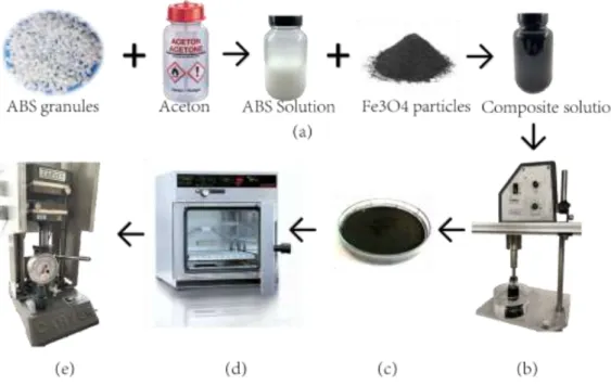
Figure 2-1 The fabrication process of the ABS-based ferromagnetic composite includes 5 steps. . - 57 -
Figure 2-2 (a)Rectangular-shape sample; (b) cylinder-shape sample; (c) different content of rectangular samples (from left to right): Fe3O4@ABS, copper@ABS, carbon black@ABS, pure ABS, Mn-Zinc@ABS, Ni@ABS; (d) needle-shaped samples. ... - 58 -
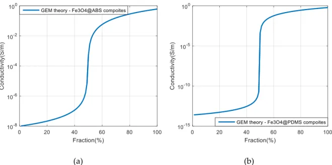
Figure 2-3 Conductivity as a function of particle volume fraction based on GEM theory: (a) curve for Fe3O4@ABS composite; (b) curve for Fe3O4@PDMS composite. ... - 60 -
Figure 2-4 GEM theory model and the measurement results of 𝜎𝐹𝑒3𝑂4 ... - 60 -
Figure 2-5 Magnetic induction distribution in a magnetic polymer composite homogeneously filled with magnetic particles. ... - 61 -
Figure 2-6 Permeability simulation predicted value versus particle percentage ... - 62 -
Figure 2-7 Photo of LCR Meter (Keysight E4980AL, Agilent) ... - 62 -
Figure 2-8 The relative permeability of Fe3O4@ABS composites measured by LCR Meter ... - 63 -
Figure 2-9 Effective medium theory of permeability as a function of particle fraction in 4 different models ... - 65 -
Figure 2-10 The experimental values (Fe3O4@ABS) fit with mixing law ... - 65 -
-
Figure 2-13 Fe3O4@ABS composites hysteresis loop in different particle fractions under frequency of
1Hz and voltage excitation of 5V. ... - 68 -
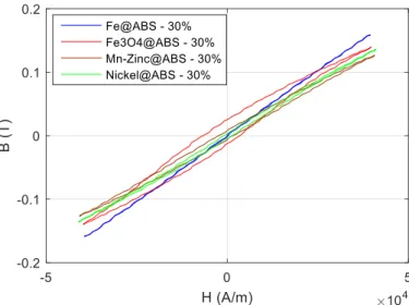
Figure 2-14 Hysteresis loop of different ABS-base magnetic composites at a frequency of 1Hz and voltage excitation of 20V. ... - 68 -
Figure 2-15 Thermal properties characterization setup for Fe3O4@ABS composites ... - 70 -
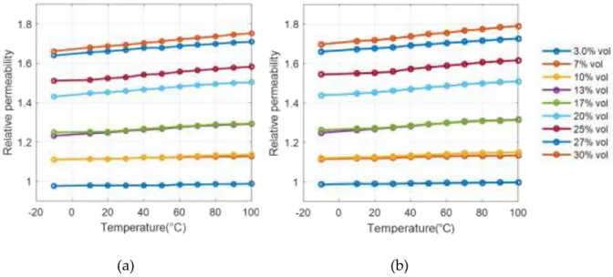
Figure 2-16 Changes in permeability over temperature for different fraction Fe3O4@ABS composites act under (a) 1 KHz; and (b) 1 MHz. ... - 71 -
Figure 2-17 The relative permeability variation under the each frequency: (a) 10% vol. Fe3O4@ABS; (b) 30% vol. Fe3O4@ABS composites. ... - 71 -
Figure 2-18 (a) Relative permeability spectra of the 30% vol. Fe3O4 composite under different temperatures. (b) Relative permeability change (%) of the 30% vol. Fe3O4 composite as a function of temperature. ... - 72 -
Figure 2-19 Fe3O4@ABS composites theoretical thermal conductivity (red line) and specific heat (blue line) as a function of iron oxide content. ... - 73 -
Figure 2-20 Thermal conductivity test bench JEULIN ... - 74 -
Figure 2-21 Thermal conductivity of (a) Fe3O4@ABS composites; (b) Nickel@ABS composites. ... - 75 -
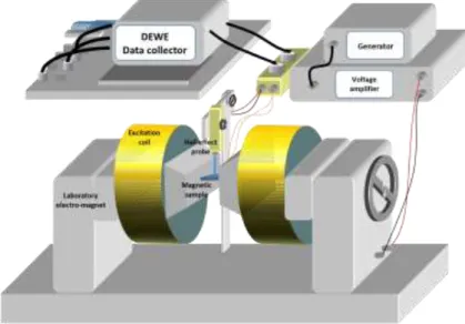
Figure 3-1 Experimental setup schematic diagram of the induction heating effect. ... - 77 -
Figure 3-2 Design of the magnetic inductor with permanent magnets ... - 77 -
Figure 3-3 (a) the magnetic strength and induced voltage of the magnetic field created by the 8-magnets inductor (b) the Fourier transformer of frequency ... - 78 -
Figure 3-4 FFT spectra of magnetic field ... - 79 -
Figure 3-5 Real shot pictures of induction heating test setup. ... - 79 -
Figure 3-6. (a) 8-magnet and 16-magnet inductors. (b) FFT spectra of magnetic field driven by the two types of inductors under 35 kRPM motor speed. Inset: Time evolution of the magnetic excitation induced from measurement with the H-coil. ... - 80 -
Figure 3-7 The induced voltage from the secondary coil acting on the (a) 8-magnets inductor; (c) 16-magnets inductor. The amplitudes changes with the distance between the coil sensor and (b) 8-magnets inductor; (d) 16-8-magnets inductor. ... - 81 -
Figure 3-8 LFIH observation under 2.3 kHz AC magnetic field excitation. a) Ferromagnetic composite with17% vol. of iron oxide; b) conductive composite with 15% of copper oxide. ... - 82 -
Figure 3-9 Temperature versus time at different motor speeds (kRPM). (a) Continuous lines relate to the T° of hot source; (b) dotted lines referred to the T° at the center. ... - 84 -
under 2.3 kHz AC magnetic field excitation. ... - 84 - Figure 3-12 (a) Time evolution of temperature at different distances between the composite and the magnetic inductor. Continuous lines show to the T° of hot source whereas dotted lines show the T° at the center. (b) The amplitude of the magnetic field as a function of distance. (c) Final temperature versus magnetic intensity. ... - 85 - Figure 3-13 Time evolution of the temperature of Fe3O4@ABS composites at different particle fraction
excited by (a) the 8-magnet inductor and (b) the 16-magnet inductor. ... - 86 - Figure 3-14 (a) Temperature evolution of the 25% Fe3O4 composite using two different inductor excitations; (b) Temperature variation of two magnetic sources ∆𝑇16/8 as a function of duration.- 87 -
Figure 3-15 Temperature of all Fe3O4@ABS composites with different fractions after (a) 50 s; (b) 250s
... - 88 - Figure 3-16 The time constant as a function of a) volume content, b) frequency of magnetic field, and c) amplitude of magnetic field. ... - 89 - Figure 3-17 Effect of particle size on isotropic Fe3O4@ABS composites permeability ... - 90 -
Figure 3-18 Final temperature of Fe3O4@ABS composites with particle size of 50-100nm, 5µm, and
50µm on low frequency induction heating effects. ... - 90 - Figure 3-19 Hysteresis curves of 30% vol. Fe3O4@ABS composites with the size of 50 μm, 5 μm and
50-100 nm (from top to bottom) measured at a frequency of 1 Hz with voltage excitation of 20V. .... - 90 - Figure 3-20 Density energy-versus-magnetic field amplitude of Fe3O4@ABS composites with particle
size of 50 μm, 5 μm and 50-100 nm. ... - 91 - Figure 3-21 Coercivity dependence of magnetic particle size... - 92 - Figure 3-22. (a) Temperature versus time of 30% vol. Fe3O4 composites with different thicknesses. (b)
Maximum temperature of the 20% vol. and 30% vol. samples as a function of thickness for the 8-magnet sources. ... - 93 - Figure 3-23 Temperature versus time for needle composites filled with 25% vol. and 30% vol. Fe3O4using an (a) 8-magnet inductor and a (b) 16-magnet inductor. ... - 94 -
Figure 3-24 (a) Temperature versus time for composites filled with different types of ferromagnetic particles. (b) Temperature in terms of modeled magnetic heat power for Fe3O4, Ni, and Mn Zinc
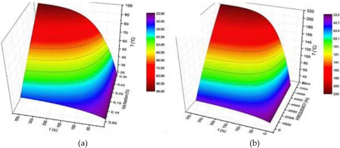
composites at a magnetic field of 160 kA/m amplitude and 2300 Hz frequency. ... - 96 - Figure 3-25. Spatial evolution of temperature for the macroscopic scale of the ferromagnetic composite with a) 3% vol. fraction, c) 10% vol. fraction and c) 17% vol. fraction under 2300Hz magnetic field excitaion ... - 98 - Figure 3-26. Theoretical and experimental temperatures as a function of time for the 17% vol.. fraction composite under 2300Hz magnetic field excitation... - 98 -
composites at excitation frequency of 2300, 4200Hz ... - 99 -
Figure 3-28. (a) Microscopic scale of the ferromagnetic composite. Heat transfer of particles with (b) 3% vol. fraction, (c) 10% vol. fraction, and (d) 17% vol. fraction. ... - 100 -
Figure 3-29. Magnetic heat power (MHP) versus frequency (a) of Fe3O4 particle and (b) of composite doped with 17% vol. ... - 100 -
Figure 3-30. Performance of induction heating in terms of (a) volume fraction and (b) frequency of the magnetic field. ... - 102 -
Figure 3-31. (a) Time evolution of temperature with different sample thickness at optimal fraction and frequency of the magnetic field. (b) Time constant versus heating temperature for various thickness values. ... - 102 -
Figure 3-32 Working principal of ferromagnetic composite guide wire (FCGW) for varicose vein treatment. (a) Three principal steps in the procedure; (b) FCGW-design-based Fe3O4composite. - 103 - Figure 3-33 LFIH observation based thermal camera for big needle composite filled with 30% vol. Fe3O4 particles using (a) the 8-magnet inductor, and (b) the 16-magnet inductor. ... - 104 -
Figure 3-34 Spatial temperature evolution of two needle composites filled with 30% vol. iron oxide using (a) an 8-magnet inductor and (b) a 16-magnet inductor. ... - 105 -
Figure 3-35 Theoretical and experimental temperatures as a function of time for the big needled composites filled with 30% vol. Fe3O4excited by two different inductors. ... - 105 -
Figure 4-1 Schematic representation of particles: (a) randomly distribution; (b) structured particle distribution ... - 108 -
Figure 4-2 Simulation images of magnetic particle arrangement obtained by magnetophoresis of 0.2 T amplitude along the horizontal direction [113]. ... - 109 -
Figure 4-3 Simulation images of random and aligned composites filled with 40% of ferrite particles. Magnetophoresis is performed in the horizontal direction [113]. ... - 110 -
Figure 4-4. Illustration of the different methods proposed in the literature to provide a stable magnetic field during the curing step. ... - 112 -
Figure 4-5 Fabrication process of anisotropic ferromagnetic composites ... - 114 -
Figure 4-6. Overall 3D view and photos of both cubic mold and the cubic sample. ... - 114 -
Figure 4-7. Magnetic field measurement on the permanent magnet surface. ... - 115 -
Figure 4-8. Magnetic field driven by two permanent magnets. (a) Setup design for performing anisotropy composite. (b) Overall 3D view of magnetic distribution based Comsol simulation .... - 116 -
Figure 4-9. Magnetic field distribution in the sample area with space gap of: (a) 5 mm, (b) 3 mm, (c) 2 mm, (d) 1 mm. ... - 116 -
samples (US) with different thickness of 1, 2 and 3 mm. (b) Steady-state temperature as a function of the thickness. (c) Steady-state temperature difference between oriented and un-oriented samples as
a function of the thickness. ... - 118 -
Figure 4-12. SEM image of anisotropy composite-based micro-structure. ... - 119 -
Figure 4-13. SEM images and directionality histogram of (a) oriented sample with magnification of x420; (b) un-oriented sample with magnification of x420; (c) oriented sample with magnification of x120; (d) un-oriented sample with magnification of x120. ... - 120 -
Figure 4-14. (a) Large window SEM and directionality histogram of 5% vol. Fe3O4 oriented composite. (b) SEM and directionality histogram of 15% vol. Fe3O4. ... - 121 -
Figure 4-15. Test bench used for determination of permeability: (a) Inductance measurement based LCR meter. (b) Relative permeability of random sample and oriented samples (z-axis and x, y-axis) as a function frequency. ... - 122 -
Figure 4-16 Permeability of (a) un-oriented and (b) oriented Fe3O4 @PDMS composites in particle size of 50-100nm, 5um and 50um. ... - 122 -
Figure 4-17 Hysteresis cycle of (a) un-oriented Fe3O4 @PDMS composite, and (b) oriented Fe3O4 @PDMS composite under magnetic field of 1Hz frequency and 40 kA/m. ... - 123 -
Figure 4-18. The LFIH measurement as a function of the anisotropy sample. ... - 124 -
Figure 4-19. Temperature versus time plot for increasing particles volume fraction samples. a) Z-axis of oriented composite; b) Z-axis of un-oriented composite. ... - 124 -
Figure 4-20. (a) Steady state temperature as a function of particles volume fraction for both aligned and random composites subjected by different orientations of magnetic field. (b) Temperature difference between the z-axis (preferred orientation) and the x, y-axis of the anisotropic samples. .... - 125 - Figure 4-21. (a) Temperature as a function of time, comparison easy axis/other axis. (b) Time response ratio R between z-axis and x, y-axis of oriented samples as a function of particle volume fraction.- 126 - Figure 4-22 Working principal of electromagnetic tracking based ferromagnetic composite ... - 128 -
Figure 4-23. Flexible ferromagnetic composite based PDMS polymer elaborated with 30% Fe3O4 particles ... - 128 -
Figure 5-1 Printing paste preparation. ... - 133 -
Figure 5-2 3D printing process flow chart. ... - 134 -
Figure 5-3 How to make 3D printed composite ... - 135 -
Figure 5-4. LFIH result of printed ferromagnetic composite: a) Injection of PDMS + 15% Fe3O4 solution from printer nozzle; b) IH observation through a thermal camera. ... - 135 -
particles: (a) Sample using casting method; (b) Pattern letters using printing technology. ... - 137 - Figure 5-7 Schematic diagram of magnetic source: (a) Vertical array with north up; (b) Horizontal array with north side; and (c) Halbach array. ... - 138 - Figure 5-8 Magnetic flux density of a single permanent magnet: (a) measured by hall probe; and (b) Simulation using Comsol software. ... - 139 - Figure 5-9 Magnetic field distribution of (a) vertical array; (b) horizontal array; and (c) Halbach array.- 140 -
Figure 5-10 Magnetic flux density (B) versus z-distance of (a) vertical array; (b) horizontal array; and (c) Halbach array. ... - 141 - Figure 5-11 Customized magnetic source including magnet array embedded into plastic substrate ... - 141 -
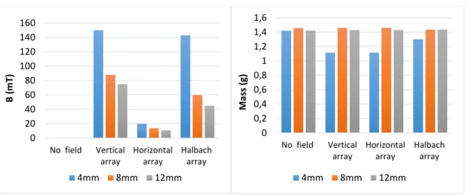
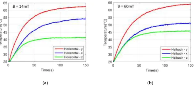
Figure 5-12 (a) Schematic and (b) physical image of 3D printing set up. ... - 142 - Figure 5-13 Distance influence of a) the magnetic flux density; and b) the mass for the printed composites under 4 setup configurations. ... - 144 - Figure 5-14 Inject syringe attached with (a) stainless steel tip (PSS); and (b) plastic tip (STT). ... - 144 - Figure 5-15 Comparison of samples’ properties printed with PSS tip and STT tip: (a) heating temperature difference of LFIH test; (b) relative permeability ... - 145 - Figure 5-16 Samples printed with STT tip under 4 configurations: (a) without magnetophoresis; and with magnetophoresis consisting of (b) vertical array; (c) horizontal array; and (d) Halbach array- 146 -
Figure 5-17 Cubic-shape samples printed under the two types of horizontal magnetic field. ... - 147 - Figure 5-18 Permeability test in 3 directions: (a) x-axis; (b) y-axis; and (c) z-axis ... - 148 - Figure 5-19 Relative permeability of printed cubic sample in different axis. ... - 149 - Figure 5-20 Time evolution of temperature measured on cubic samples subjected to magnetophoresis using (a) horizontal array; and (b) Halbach array. ... - 150 - Figure 5-21 (a) Permeability test in y-axis direction; (b) Relative permeability versus frequency of un-oriented and un-oriented samples with and without magnetiphoretic process. ... - 151 - Figure 5-22 (a) IH test in z-axis direction; (b) Temperature versus time plot for sample printed under different magnetophoretic conditions. ... - 152 - Figure 5-23 (a) Thermal conductance pathways generated by particle chain-like structure; (b) Heat dissipation of composites aligned in z-axis and y-axis . ... - 153 - Figure 5-24 Measurement via thermal conductivity analyzer[152] ... - 154 -
Tableau 2-1 The coefficient of hysteresis loop in one cycle period for Fe3O4@ABS composites in different fraction. ... - 68 - Tableau 2-2 Coefficient of hysteresis cycle samples with different ABS-base magnetic composites.- 69 -
Tableau 2-3 The theoretical and experimental thermal conductivity of composites. ... - 74 - Tableau 3-1 Temperature change (∆𝑇) of the big and small needles doped with 25% and 30% iron oxide based two different magnetic sources. ... - 94 - Tableau 3-2 Resume of other ABS based magnetic composites’ properties ... - 96 - Tableau 3-3 Simulation thermal parameters of the macroscopic composite model with different contents of the particle at magnetic field frequency of 2300Hz and 4200Hz. ... - 98 - Tableau 4-1 The coefficient of hysteresis loop in one cycle period for Fe3O4@PDMS composites - 123 -
Table 5-1 Measured values of the magnetic flux density (B) and the average mass (M) of 30% vol. Fe3O4@PDMS composites printed at various distances from the array surface. ... - 143 -
Table 5-2 Thermal conductivity and specific heat capacity of the random and oriented composites measured in different direction ... - 154 -
Les Résumé de Thèse en Français
Chapitre 1 - État de l’art
1.1
Les matériaux ferromagnétiques
Les matériaux magnétiques peuvent être classés en six catégories: matériaux diamagnétiques, matériaux paramagnétiques, matériaux ferromagnétiques, matériaux ferrimagnétiques, matériaux antiferromagnétiques et matériaux super-paramagnétiques.
Les matériaux ferromagnétiques présentent de grandes dépendances aux champs magnétiques externes. Des propriétés magnétiques rémanentes sont observées une fois le champ externe supprimé. Le fer, le nickel et le cobalt sont des exemples de matériaux ferromagnétiques.
Les matériaux ferromagnétiques sont composés de petites zones appelées domaines magnétiques. Dans un domaine magnétique, tous les moments atomiques sont dirigés selon une même direction et orientation. Dans un état désaimanté, l’aimantation résultante issue de l’ensemble des domaines magnétiques s'annule.
Sou l’effet d’un champ externe, les domaines magnétiques caractérisés par un moment magnétique présentant une direction et une orientation proches de celles du champ externe gagnent en énergie et croient tandis que les autres rétrécissent et disparaissent.
Ce phénomène se prolonge jusqu'à ce que l'aimantation atteigne une valeur seuil dite de saturation ou plus aucune variation n’est observée. Une fois cet état saturé atteint, la réduction du champ d’excitation conduit à une distribution des domaines magnétiques déséquilibrée appelée magnétisation rémanente, ou encore magnétisation résiduelle. Si le champ d’excitation est inversé, le matériau retourne vers une distribution en domaines magnétiques plus équilibrée ou différentes directions et orientations sont observées (coercivité) et ou l’état magnétique moyen et proche de zéro.
Figure 1. Processus d’aimantation, cinétique des domaines magnétiques.
Le cycle d'hystérésis représente l’évolution du champ d'induction magnétique B en fonction du champ d’excitation magnétique H d'un matériau magnétique (figure 1). Le cycle d'hystérésis est un outil de caractérisation du comportement magnétique. Il est en général attribué aux mouvements des parois des domaines magnétiques. L’aire du cycle d'hystérésis est égale à l'énergie dissipée par un matériau de volume unitaire lors d’un cycle de fonctionnement. La variation ΔB en fonction de ΔH lue sur le cycle d’hystérésis est appelée perméabilité différentielle. Le cycle d'hystérésis est une caractéristique intrinsèque du matériau qui peut varier en taille et en forme.
1.2
Les composites ferromagnétiques
Les matériaux magnétiques sont utilisés dans une large gamme d'applications scientifiques et technologiques. Des particules magnétiques distribuées dans une matrice polymère donnent naissance à un composite magnétique (matériaux multifonctionnels). La nature des particules a une influence significative sur le comportement magnétique du composite. La fraction volumique et l'orientation spatiale ont également un impact significatif.
Dans ce travail de thèse, nous souhaitons développer une méthode de Chauffage par Induction Basse Fréquence (CIBF) de composites ferromagnétiques dans un objectif médical : le traitement des varices. L’objectif final étant médical, le composite que nous allons développer doit être biocompatible. Nous avons identifié des particules d'oxyde de fer (Fe3O4) de 5 µm de
diamètre comme étant un bon candidat pour ce qui concerne les particules. Pour justifier ce choix, nous avons comparé les performances de ces particules à celles d'autres particules ferromagnétiques (Ni, Mn-Zinc ...).
Les propriétés magnétiques des composites ferromagnétiques dépendent également de façon indirecte à la matrice polymère. En fonction de la distribution et de l’orientation des particules au sein de la matrice, les composites ferromagnétiques peuvent entre autres présenter des
comportements anisotropes. Les composites anisotropes se caractérisent par des propriétés physiques qui dépendent de la direction spatiale. Dans cette thèse, des composites ferromagnétiques isotropes et anisotropes ont été étudiés. Pour ce qui concerne la matrice polymère des composites isotropes, l'ABS thermoplastique a été choisi (ce polymère est très disponible, sa fabrication et ses propriétés physiques sont bien maitrisées). Pour les composites anisotropes nous avons plutôt opté pour le PDMS. Le PDMS permet d’obtenir un composite biocompatible extrêmement flexible, particulièrement bien adapté pour le traitement des varices et la technique CIBF.
1.3
L’effet CIBF
L'effet CIBF peut être défini comme l'élévation de température observée dans un matériau ferromagnétique sous l'influence d'un champ magnétique alternatif basse fréquence. La source de chaleur provient principalement des pertes par hystérésis et de l'effet des courants de Foucault. L'effet CIBF est principalement dû aux courants de Foucault dits "microscopiques". Des pertes par hystérésis sont observées dès lors qu’un matériau ferromagnétique est exposé à un champ magnétique alternatif. L’excitation magnétique conduit à un arrangement des domaines magnétiques. Etant alternatif, le champ d'excitation induit des mouvements alternés des parois des domaines magnétiques qui s'accompagnent de pertes énergétiques. Ces pertes proviennent des courants de Foucault dits «microscopiques», interactions entre les parois des domaines magnétiques et la microstructure lors de l’aimantation de l'échantillon ferromagnétique.
A hautes fréquences, une conversion magnétothermique élevée peut être atteinte. Cependant, une fréquence trop élevée (> 100 kHz) est bannie dans le domaine médical car des dommages indésirés peuvent être observés sur le corps humain. Selon les directives de la commission internationale de protection contre les rayonnements non ionisants (ICNIRP), la gamme dite des « basses fréquences » s'étend de 1 Hz à 100 kHz. Au-delà des 100 kHz, des effets de chauffage indésirés doivent être pris en compte.
Jusqu'à présent, les champs magnétiques basses fréquences ont rarement été exploités pour des applications médicales. Dans cette thèse, deux applications potentielles sont particulièrement ciblées:
_ le traitement des varices _ le suivi électromagnétique.
La traitement des varices par ablation thermique consiste à insérer un composite ferromagnétique biocompatible dans la veine à traiter. Puis de le chauffer par un champ magnétique externe alternatif basses fréquences (moins de 50 kHz) et d’induire la cicatrisation de la veine à traiter. L'effet CIBF commence dès lors que l'échantillon ferromagnétique est exposé au champ magnétique alternatif. Etant basse fréquence, le champ magnétique alternatif est censé chauffer uniquement le composite ferromagnétique. La destruction de la veine malade peut intervenir sans endommagement des tissus sains environnants. Selon nos analyses de calorimétrie différentielle à balayage (DSC) effectuées sur des varices provenant du corps d’un patient, le point de fusion de la veine est proche des 120 ° C.
Dans cette thèse nous proposons une méthode alternative pour le traitement des varices basée sur le mécanisme CIBF. Notre méthode est proche de la technique d'ablation thermique endoveineuse (EVTA). Notre objectif n'est pas de la concurrencer mais plutôt d’exposer les bénéfices de la méthode CIBF. Nos résultats de simulation et expérimentaux sont prometteurs, ils montrent un fort potentiel de la méthode proposée. La méthode CIBF repose sur les courants de Foucault dits microscopiques, générés à l'intérieur des particules magnétiques sous l'influence d'une source magnétique alternative. Comme l'excitation magnétique reste à l'extérieur du patient et qu'aucune connexion physique n'existe entre le cathéter ferromagnétique et la source énergétique, la méthode CIBF conduit à une procédure beaucoup plus confortable pour le chirurgien. La sélectivité de l'effet CIBF qui n’agit que sur le matériau ferromagnétique rend quasi impossible la brûlure de tissus voisins. De plus, la méthode CIBF est moins coûteuse. Finalement, le cathéter ferromagnétique peut être imprimé en 3D avec des formes et des tailles adaptées et variables d’un patient à l’autre.
2) Les capteurs électromagnétiques: système de suivi
Les interventions chirurgicales assistées par ordinateur (IAO) se caractérisent par une grande précision, ainsi qu'un temps d'intervention réduit. Elles font désormais partie intégrante de la médecine moderne. Une localisation spatiale des outils d’intervention est indispensable pour un contrôle en temps réel. La localisation de l'appareil dans le corps du patient est appelée «tracking», c'est une technologie clé pour l’IAO.
La localisation par suivi électromagnétique (LSE) repose sur de petits capteurs/récepteurs qui circulent à travers un champ magnétique généré par un électroaimant émetteur (Figure 2). Cet émetteur est chargé de produire des champs magnétiques alternatifs ou quasi-statiques. Ces champs vont induire des courants dans les capteurs embarqués qui vont agir comme des détecteurs. Le phénomène physique derrière ces systèmes de poursuite repose principalement sur l'induction magnétique.
Figure 2. Schéma de principe d’un système de localisation par suivi électromagnétique.
Jusqu’à présent, les systèmes LSE souffrent de deux inconvénients majeurs: _ Ils sont trop volumiques pour pouvoir intégrer des instruments chirurgicaux;
_ Ils présentent des sensibilités importantes aux objets métalliques de proximité (équipement médical …) qui peuvent déformer ou perturber le champ magnétique source et induire des divergences dans la précision du système.
Pour améliorer cette précision, des composites ferromagnétiques anisotropes avec une perméabilité dépendante de la direction peuvent être une bonne solution. Qu’ils soient sous forme de capteurs ou de récepteurs, l’utilisation de composites ferromagnétiques anisotropes peut être envisagée. Dans les chapitres suivants, nous nous concentrerons sur la caractérisation et la validation de composites ferromagnétiques développés pendant ces travaux de thèse, la faisabilité et les performances de l’effet CIBF sur des composites de type anisotropes et isotropes. Nous nous intéresseront également au traitement des varices. Finalement, l’utilisation de composites ferromagnétiques pour les systèmes LSE sera décrite dans le chapitre 4.
Chapitre 2 - Caractérisation des composites ferromagnétiques
isotropes
La caractérisation des composites ferromagnétiques développés dans cette thèse est une étape cruciale. Elle nous aidera à comprendre les propriétés des composites et à améliorer leurs performances. Dans ce chapitre, les méthodes de fabrication et de caractérisation de composites isotropes seront décrites. Les évaluations théoriques et mesures expérimentales de la conductivité, la perméabilité et des propriétés thermiques seront proposées. Nous nous concentrerons particulièrement sur le comportement de l'hystérésis magnétique et sa relation étroite avec l'effet CIBF.
2.1
Fabrication de composites ferromagnétiques
Notre objectif est de fabriquer des composites avec un pourcentage élevé de particules ferromagnétiques (offrant des perméabilités et des réponses thermiques importantes). Nous avons opté pour une méthode robuste de «pressage à chaud» utilisant une presse à chaud. Grâce à la méthode du «pressage à chaud», nous avons construit avec succès des échantillons de différents pourcentages de particules magnétiques (de 3 à 30% vol.), de formes rectangulaires (60 × 14 × 4 mm, figure 3 (a)) et de formes cylindriques (Ø30 mm, épaisseur 15 mm, figure 3 (b)). Outre les composites Fe3O4@ABS, des composites non-ferromagnétiques
mais dopés de particules conductrices: 15% vol. de cuivre et 3% vol. de noir de carbone ont également été fabriqués pour vérifier l'effet CIBF sur des composites formés de particules conductrices mais non ferromagnétiques. Finalement d'autres composites ferromagnétiques (10%, 23% et 40% vol. Fe3O4, 15% vol. Ni et 30% vol. Mn-Zinc) ont également été fabriqués
pour tester d’autres paramètres.
L'échantillon présenté sur la figure 3(a) est trop grand pour une utilisation endo-veineuse. De ce fait, une autre série d’échantillons en forme d'aiguille a été développée. Deux tailles différentes ont été testées: la grande taille 40 × 3,1 × 3,2 mm3, et la petite taille 27 × 2,5 × 3,2 mm3
(Figure 3 (d)). Ces deux tailles peuvent être utilisées pour le traitement endo-veineux, elles sont en bonne adéquation avec les diamètres habituels des veines du corps humain (4 à 5 mm). De façon classique pour les composites biphasés, il existe une fraction volumique de particules critique appelée seuil de percolation ∅c définissant la limite entre l’état électrique non conducteur et l’état conducteur. Dans ce travail, pour prédire ∅c, nous avons utilisé la théorie des milieux effectifs. Nous avons estimé à 47% vol. la fraction volumique critique (seuil de percolation) pour le Fe3O4@ABS. Pour un pourcentage inférieur au seuil de percolation, la
conductivité électrique est de l’ordre de 10-6 S/m et le composite peut être classé comme isolant.
Figure 3. (a) Échantillon de forme rectangulaire; (b) un échantillon de forme cylindrique; (c) échantillons rectangulaires de différentes natures (de gauche à droite): Fe3O4@ABS, cuivre@ABS, noir de carbone@ABS, ABS pur, Mn-Zinc@ABS,
Ni@ABS; (d) échantillons en forme d'aiguille.
2.2
Caractérisation magnétique
Pour la caractérisation magnétique de nos composites ferromagnétiques nous nous sommes concentrés dans l’estimation de leurs perméabilités. Différentes méthodes ont été testées: _ En simulation à l’aide d’un outil numérique.
_ Par mesure spectroscopique d'inductance. _ A l’aide d’un modèle analytique.
_ A partir de cycles d'hystérésis expérimentaux.
1) Outil numérique
Une simulation par éléments finis à l'aide du logiciel Comsol® a été réalisée pour l'estimation de la perméabilité relative μr. La perméabilité relative des composites magnétiques obtenue en fonction de la fraction volumique de particules est représentée sur la figure 4. Comme anticipé de façon intuitive, la matrice polymère mélangée à une plus grande quantité de particules magnétiques conduit à des propriétés magnétiques améliorées (perméabilité plus élevée).
Figure 4. Evolution de la perméabilité relative en fonction du pourcentage de particules (issue de la simulation Comsol®).
2) Mesure spectroscopique de l'inductance
Pour caractériser l’évolution de la perméabilité sur une large plage de fréquences (20 Hz à 1 MHz), des mesures d'inductances ont été effectuées à l'aide d'un impédancemètre.
La perméabilité magnétique est mesurée à l'aide de la mesure de l’inductance d'une bobine enroulée autour de l’échantillon de composite magnétique. La perméabilité effective est dérivée de la mesure d'inductance. Tous les échantillons de forme cylindrique (y compris l'ABS pur) ont été encerclés par une bobine de 100 spires. La perméabilité relative (μr) a été obtenue en utilisant l'équation 1 (ci-dessous) et en supposant toutes les bobines identiques:
𝜇𝑟 =
𝐿𝑐𝑜𝑚𝑝𝑜𝑠𝑖𝑡𝑒
𝐿𝑝𝑜𝑙𝑦𝑚𝑒𝑟
Equation 1
𝐿𝑐𝑜𝑚𝑝𝑜𝑠𝑖𝑡𝑒 et 𝐿𝑝𝑜𝑙𝑦𝑚𝑒𝑟 désignent respectivement l'inductance du composite ferromagnétique et
celle du polymère pur.
On peut voir sur la figure 5 que les perméabilités relatives résultantes des composites de Fe3O4@ABS varient de 1 pour les 3% vol. de particules à 1,8 pour le 30% vol.. μr augmente
Figure 5. Evolution de la perméabilité relative des composites de Fe3O4@ABS
mesurée à l’aide de l’impédancemètre.
3) Loi de mélange, utilisation d’un modèle analytique
La prédiction de la perméabilité magnétique effective (perméabilité moyenne d'un milieu non homogène) d’un composite ferromagnétique est à l’origine de nombreux travaux académiques et industriels. Au cours des dernières décennies, de nombreux progrès ont été accomplis autour des théories efficaces de mélanges, comme la formule de Maxwell-Garnett, la formule de Bruggeman, la formule du potentiel cohérent et bien d’autres. Parmi tous ces modèles prédictifs, le modèle non sphérique de Bruggeman est celui qui semble donner les meilleurs résultats de simulation pour nos composites isotropes Fe3O4@ABS (particules de 5 μm).
Comme on peut le vérifier sur la figure 6, les valeurs expérimentales suivent parfaitement la courbe théorique.
Figure 6. Comparaison de l’évolution théorique et expérimentale de la perméabilité relative de composites Fe3O4@ABS en fonction du pourcentage de
4) Courbe d'hystérésis
Les cycles d’hystérésis de tous nos composites ferromagnétiques ont été mesurés à l’aide d’un dispositif expérimental dédié incluant un électroaimant de laboratoire. Les spécimens de forme cylindrique (figure 3 (b)) sont bien adaptés et ont fait l’objet de cette caractérisation. La figure 7 représente les cycles d'hystérésis des composites ferromagnétiques obtenus sous une excitation magnétique sinusoïdale de 1 Hz, 17 kA.m-1.
Figure 7 Cycle d’hystérésis des composites Fe3O4@ABS dopés de différentes
fractions de particules (1Hz).
Comme prévu, une teneur plus élevée en Fe3O4 conduit à des cycles d'hystérésis plus raides et donc des valeurs de perméabilité plus élevées. La surface du cycle d'hystérésis augmente également légèrement en fonction de la fraction des particules.
2.3
Caractérisation thermique
L’étude de l'influence de la température sur les propriétés magnétiques est une étape obligatoire dans la conception de notre composite.
Pour vérifier l’influence de la température, de nouvelles mesures d'inductance et indirectement de perméabilités des échantillons composites Fe3O4@ABS (figure 3 (a)) ont été
effectuées à l’aide de l’impédancemètre. La largeur de la bande de fréquence testée a été réglée à 1 kHz - 1 MHz (en concordance avec les applications typiques de chauffage par induction). Ces tests expérimentaux ont été réalisés en plaçant les composites à l'intérieur du four pour des températures variants de –20 ° C à 100 ° C.
Finalement, nous avons pu constater qu’indépendamment des variations de fréquences, les composites testés présentent des propriétés magnétiques relativement stables. La perméabilité magnétique d’un échantillon donné pour une fréquence donnée est quasiment constante dans la plage de températures testée. (Figure 8)
(a) (b)
Figure 8 Variation de la perméabilité en fonction de la température pour des composites de Fe3O4@ABS à (a) 1 KHz; et à (b) 1 MHz.
De plus, un dispositif de caractérisation dédié a été utilisé pour mesurer la conductivité thermique des composites. Les composites Fe3O4@ABS (3, 8 et 17% vol. de particules), les
composites Ni@ABS (10, 23, 40% vol. de particules), ainsi que l'ABS pur ont été caractérisés. Les résultats expérimentaux se sont révélés en bonne adéquation des résultats théoriques. Dans le chapitre suivant, l'effet CIBF pour des composites ferromagnétiques isotropes est étudié. Une analyse complète des paramètres impliqués dans le mécanisme CIBF est proposée.
Chapitre 3 - Effet CIBF des composites ferromagnétiques
isotropes
Dans cette partie, nous nous concentrons sur l’effet de chauffage par induction basse fréquence (CIBF). Celui-ci est appliqué à des composites ferromagnétiques isotropes constitués d’un polymère thermoplastique (acrylonitrile butadiène styrène, ABS) dopé de particules magnétiques d'oxyde de fer (Fe3O4). L'effet CIBF apparaît dès lors que l'échantillon est exposé
à un champ d'excitation magnétique alternatif et est principalement dû aux courants de Foucault dits «microscopiques» associés aux mouvements des parois des domaines magnétiques. Ce phénomène (CIBF) peut être influencé par divers facteurs, incluant des paramètres liés aux composites (son contenu, sa nature, la taille des particules magnétiques, sa dimension …) mais également la forme d’onde de l'excitation magnétique (fréquence, amplitude …). Une simulation Comsol® basée sur le transfert thermique et associée à des résultats expérimentaux, a permis de démontrer la possibilité de chauffer par induction notre composite ferromagnétique jusqu'à des températures supérieures à 100 ° C. Une optimisation de la source magnétique et de la fraction particulaire du matériau doit permettre de nouveaux progrès. Ces résultats sont particulièrement encourageants et prometteurs pour le traitement endo veineux thermique par méthode CIBF.
3.1
Configuration CIBF
Pour la validation expérimentale de l'effet CIBF, un banc de caractérisation expérimental spécifique a été développé (Figure 9). Pour générer une excitation de champ magnétique alternative significative, un inducteur magnétique comprenant plusieurs paires d'aimants permanents cylindriques a été fixé sur l’arbre moteur d’une machine tournante haute vitesse. Comme nous pouvons le voir figure 10, la distribution polaire de ces aimants permanents est alternativement sud/nord, ceci permet de générer une excitation magnétique sinusoïdale dont la fréquence est directement liée à la vitesse de rotation du moteur grande vitesse. En pratique, avec une vitesse de rotation maximale (supposée de 35000 tr/min, donnée constructeur), l’inducteur 8 aimants permet d’atteindre un champ magnétique alternatif de 2300 Hz, celui à 16 aimants nous donne une excitation à 4200 Hz. Pour contrôler l'amplitude du champ magnétique, nous pouvons contrôler la distance entre l'inducteur magnétique et le composite. Les variations de température sont mesurées à l’aide de deux thermocouples. Le premier thermocouple mesure la température dans la zone chaude (au plus près du passage des aimants), l'autre est utilisée pour déterminer la température du centre de l'échantillon. Les données mesurées sont enregistrées en temps réel à l’aide une carte DEWE®. Pour obtenir une image de température plus intuitive, une caméra thermique est également utilisée sur toute la durée de l'expérience.