Effect of Crystal Orientation on
Nanoindentation Behavior in Magnesium
The MIT Faculty has made this article openly available. Please share how this access benefits you. Your story matters.Citation Somekawa, Hidetoshi, and Christopher A. Schuh. “Effect of Crystal Orientation on Nanoindentation Behavior in Magnesium.” Metallurgical and Materials Transactions A 47.6 (2016): 3227–3234. As Published http://dx.doi.org/10.1007/s11661-016-3479-6
Publisher Springer US
Version Author's final manuscript
Citable link http://hdl.handle.net/1721.1/106918
Terms of Use Creative Commons Attribution-Noncommercial-Share Alike Detailed Terms http://creativecommons.org/licenses/by-nc-sa/4.0/
1
Manuscript submitted on June 13, 2015
Effect of crystal orientation on nanoindentation behavior in magnesium
Hidetoshi Somekawa 1) and Christopher A. Schuh 2)
1) Research Center for Strategic Materials, National Institute for Materials Science, 1-2-1 Sengen, Tsukuba, Ibaraki, 305-0047, Japan
2) Department of Materials Science and Engineering, Massachusetts Institute of Technology, 77 Massachusetts Avenue, Cambridge, MA02139, USA
Corresponding author;
Hidetoshi SOMEKAWA (SOMEKAWA.Hidetoshi@nims.go.jp) TEL; +81-29-859-2473 FAX; +81-29-859-2601
Christopher A. SCHUH (schuh@mit.edu)
2 Abstract
The effect of crystal orientation on nanoindentation behavior at both quasi-static and high strain rates was investigated using single crystalline magnesium oriented in basal and prismatic configurations. Both the basal and prismatic planes had similar activation volumes, 55 and 73b3 for deformation at room temperature, as well as a small temperature-dependence up to 423 K (150 C). Microstructural observations beneath the indentations revealed that {
101 2} type deformation twins were formed in both orientations irrespective of testing temperature. With twins forming beneath the indenter and multiple orientations of loading, it is believed that cross-slip and/or multiple slip are likely rate-controlling for global deformation, which also aligns with observations on nanoindentation of polycrystalline coarse-grained magnesium. The locations of the twins were consistent with expectations based on indentation mechanics as assessed by finite element simulations. The finite element simulations also predicted that an indenter tip with a shaper tip radius would tend to promote {
101 2} twins.
Keywords;
3 1. Introduction
Since magnesium has a significant difference in slip activation stress between the basal <a> planes and the non-basal prismatic <c> and pyramidal <c+a> planes, prismatic and pyramidal slip are difficult to activate at room temperature. As a result, twinning can become active as an additional mode of deformation and to compensate for the lack of a <c> component in slip. Many types of twinning, e.g., {
101 1}-, { 101 2}-, { 101 3}-twinning, and { 101 1 }-{
101 2 } double twinning, have been observed in magnesium [1-3]. The crystallographic relation of the twinning lattice is fixed, and the three single twin variants are rotated around the <
1 1 20> direction by 56, 86 and 64 respectively. In addition, {
101 1}- or {
101 2}-twinning occurs when compressive or tensile stress is applied along the <c>-axis; thus, these are called <c>-axis compression or tension twins, respectively [4]. Furthermore, {
101 2} twinning is most commonly found to occur since it has the lowest critical resolved shear stress (CRSS) among such twins. This type of twinning is well-known to be significantly anisotropic, and gives rise to large mechanical asymmetry wherein the mechanical properties are influenced by the crystal orientation, i.e., basal plane orientation distribution. For instance, wrought processed polycrystalline magnesium and its alloys, which tend to favor basal plane alignment parallel to the processing direction, show much lower yield strength in compression compared to that in tension due to the easy activation of this twinning system in compression [4].
The formation of twins under contact loads in magnesium is a more complex problem, but one that is relevant to indentation testing as well as many mechanical loading situations common in machine components. Crystal orientation is likely to play a significant role in contact loading much as it does in simpler uniaxial loading. Indeed, for other metals many papers have reported the effect of crystal orientation on measured indentation responses, including mechanical properties such as hardness and modulus, as well as incipient plasticity; this is especially true for FCC and BCC metals studied in single crystal form (e.g., Cu [5-8], Au [9-11], Pt [12], Al [6,10,13] and Ag [14]). Significantly different morphologies in the indentation pile-up pattern are observed with orientation change, and these are related to the strong crystallographic anisotropy of out-of-plane displacements around indentations. The number of available slip planes also tends to affect the indentation hardness and the “pop-in” behavior associated with discrete events like dislocation source activation. The critical stress for the onset of plasticity, i.e., the first pop-in event that corresponds to dislocation nucleation, is also influenced by anisotropy of, e.g., the shear modulus.
4
properties from such small scale mechanical tests exhibit some interesting differences from conventional testing using bulk samples, most of which pertain in some way to the multiaxiality of nanoindentation and the necessity of deformation activity in multiple directions in that mode of loading. For example, whereas bulk uniaxial tests using single crystals show strength differences of as much as ten times between basal and non-basal orientations, the difference in indentation depths (indentation hardness) between the basal and non-basal planes at constant load levels is only around 30 % [15]. As another example, our previous study found that the activation volume, V* (= 20 ~ 100b3, where b is the Burger’s vector), for both the initial yield point and plastic deformation during nanoindentation tests was several times lower than that in uniaxial testing, (V* > 1,000b3) [17]. These differences in activation volume between indentation and uniaxial testing of magnesium indicate that the rate-controlling mechanism during nanoindentation may not be the same as that in the conventional testing. The cross-slip and/or multiple slip occurs during the nanoindentation testing, while a major deformation mechanism in the uniaxial testing is the intersection of dislocations. In addition, the deformed microstructures around indentations in magnesium present some interesting aspects. Some papers showed no effect of crystal orientation on twin formation [15], while other studies reported finding no twins for the case of indentations normal to the basal plane [16,22]. The number of reports on these issues in magnesium remain few compared to those for the FCC and BCC metals, and with some differences in alloy composition and methodology between the various studies, it is difficult to identify the most influential factors giving rise to these differences. Accordingly, in this study, we explore the effect of crystal orientation on the microscopic deformation behavior of single crystalline magnesium during nanoindentation, including deformed microstructural observations and continuum simulations.
2. Experimental and numerical procedures 2.1. Experimental procedure
Single crystalline magnesium was used in this study. This single crystal was produced by Metal Crystals & Oxides Ltd. by a Bridgeman method and had a purity of 99.999 %. This sample was slowly cut using a diamond saw without any weight to study two orientations: those with basal and prismatic planes exposed. Before testing, the samples were annealed at 573 K (300 C) for 24 hrs and mechanically polished with a colloidal alumina slurry (diameter of 0,05 m), followed by a final polishing with bare cloth under
5
water for at least 10 mins. The polished samples were etched for several seconds in a solution of 10 mL HNO3, 30 mL acetic acid, 40 mL H2O and 120 ml ethanol to remove any
last residual strains on the surface. The etching depth was about 100 m, which provides a clean damage free surface for indentation [16].
The nanoindentation behavior of the basal and prismatic planes was investigated using two different indenters to access two different strain rate regimes. A Hysitron Tribo Indenter was set to loading rates of 10, 1.0, 0.1 and 0.02 mN/s. The indentation strain rate is given by the equation,
.ind = 1/h dh/dt (1)
however, the actual effective strain rate at the indentation tip, .eff, is difficult to obtain through
experiments alone, so we rely on the relation provided by prior experiments and finite element (FE) simulations ; .eff = 0.128
.
ind [25,26]. For a constant loading rate experiment,
the strain rate is known to decay over the duration of an experiment, but the variation for the greater part of the test is constant to within a factor of about 2, and thus is reasonably constant for comparison of data from different tests which usually span many orders of magnitude. As a result, the present effective strain rates correspond to about 1.3, 0.13, 0.013 and 0.0026 s-1, all in the “quasi-static” strain rate regime. These quasi-static tests were conducted exclusively at room temperature. A Micro Materials Nanotest 600 was used in impact mode to access the high strain rate regime of about 150 ~ 170 s-1. In these experiments the indenter was mounted to a pendulum and accelerated into the sample surface via electromagnetic actuation. The displacement was tracked during the impact and rebound of the tip, measured though a capacitive transducer mounted on the opposite end of the pendulum. The hardness is assessed using the energy per unit volume dissipated as plastic work during impact-induced deformation. More details on the apparatus and analysis are available in Refs. [18,27,28]. These high rate tests were conducted at a variety of temperatures ranging from 300 to 423 K (27 to 150 C). Both indenters were equipped with a cube-corner diamond tip, and a minimum of 100 and 40 indentations were analyzed for each condition in the quasi-static strain rate and the high strain rate regimes, respectively.
The initial and deformed microstructures were observed by electron backscatter diffraction (EBSD, in a field emission gun scanning electron microscope (FE-SEM) equipped with an EDAX-TSL EBSD system). The deformed microstructures beneath some selected indentations were observed on samples prepared by focused ion beam (FIB) cross-sectioning in a dual-beam FEI Helios 600, which allows the preparation of site-specific micro-samples
6
for microstructural observation. A platinum layer was deposited over the middle position of the indentation to protect the sample surface from damage by the FIB process. Deep trenches are also observed in the upper and lower parts, and all of the specimens measured about 30 45 m2
. More details on the sample preparation for EBSD observation using FIB are reported in our previous study [18].
2.2. Numerical procedure
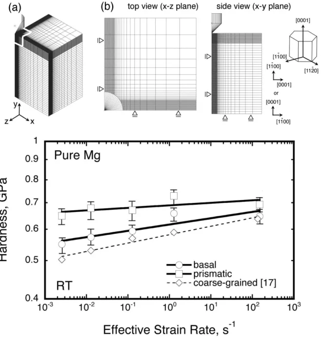
As a means of appreciating some of the effects of crystal orientation and indenter geometry, a FE simulation was carried out using the FE-code ABAQUS/Explicit, in a three-dimensional model with adaptive re-meshing applied. The images of the full simulation are shown in Fig. 1: (a) three-dimensional view and (b) two-dimensional top and side views including boundary conditions. The HCP unit cell and the two crystal orientations studied are also shown at the right-side in Fig. 1(b), which are the same as those studied experimentally. The area circled with a white solid line in Fig. 1(a) is the analyzed region, upon which we focus our attention in later sections, e.g., Figs. 5, 6 and 8.
The indenter tip consisted of a rigid blunt cone with two different tip radii, i.e., either with a sharp or blunt tip radius of 0.05 or 5.0 mm, respectively. The dimensions of the simulated indented sample domain, i.e., magnesium, were 5 x 5 x 8 mm. The friction coefficient between tip and sample was assigned as 0.1, and a Young’s modulus of 40 GPa and a Poisson’s ratio of 0.3 [29] were constant and were used for pure magnesium, because the shear modulus is only slightly affected by crystal orientation [30] and the degree of elastic anisotropy, (= 2(S11-S12)/S44, where S11, S12 and S44 are the elastic stiffness components), in
magnesium is calculated to be 0.98 [31]. Plastic flow followed the Hollomon equation, = ’0 + Kn, where ’0 corresponds to the yield strength, which was taken to be asymmetric
based on Hill’s potential function [32]. The stress ratio, Rij (= (ij)/0; where 0 is the
reference yield strength, (ij) is the yield strength for directional indices i and j i= x, y and z), which are applied in Hill’s potential function, were referred from the stress and strain relations. In the present analysis, since the yield strengths in the basal and prismatic planes are different, the values of the stress ratio are 1 or 10, respectively, i.e., (xx) = 10 and (yy) = 1 for indented to basal plane and (xx) = 1 and (yy) = 10 for indented to prismatic plane. The other values of (zz), (xy), (xz) and (yz) were set to a constant of 1, because the strains were too small to affect it [33]. The work hardening parameters, n and K, were
7
obtained from the stress-strain curves in the uniaxial testing in Ref. [1]. According to the previous results with various investigated strain rates, the strain rates do not largely affect the stress vs strain behaviors in the single crystals in the quasi-static regime [2,34,35]; hence, the effect of strain rate on these values was neglected in this study.
While more complex mechanical models (and geometries) are possible, the above choices capture the key elements of interest to the present study, namely, the effects of plastic anisotropy in a full three dimensional framework.
3. Indentation tests
The variation of hardness as a function of effective strain rate is shown for both orientations tested in Fig. 2. For comparison, this figure also includes our previously reported data for extruded coarse-grained pure magnesium with a purity of 99.94 % [17]; the extrusion process gives rise to a basal orientation preference in the texture. Since the present single crystal samples and polycrystalline magnesium from our prior work do not have the same purity, this may account for some small differences between the samples. Nonetheless, the hardness values measured upon indentation into the basal plane of a single crystal are found to be quite similar to those in coarse-grained pure magnesium with a basal texture. On the other hand, the hardness measured on the prismatic plane is around 10-20 % larger than that of the basal plane. This figure also shows that all the data series lie nearly on straight lines in this double-logarithmic presentation, despite the differences in testing method. Both of the present single crystal samples have similar slopes, which indicates a small orientation effect on the deformation mechanism under indentation loading. Furthermore, the slopes for the single crystals are almost the same as that for the coarse-grained basal-textured sample. The similarities in the slope are significant because they correspond to the activation volume, which is characteristic of the thermally activated mechanism that is rate-limiting to deformation:
(2)
where k is Boltzmann’s constant, T is the temperature, m is the strain rate sensitivity and H is the hardness. By fitting the data in Fig. 2 with Eq. (2), the activation volume, V*, is obtained as 55b3 and 73b3 for indentation on the basal and prismatic planes, respectively, where the values are normalized using the Burger’s vector of magnesium (= 3.21 10-10 m [36]). The value of V* reported in our previous work on coarse-grained basal-textured
8
magnesium is 45b3 [17], which is comparable to the present values. These results suggest that the rate-controlling mechanism during indentation over a wide effective strain rate range, ~ 1 10-3
- 150 s-1, is not strongly influenced by crystal orientation.
The variation of impact hardness as a function of temperature in the dynamic strain rate range is shown in Fig. 3. As expected, the impact hardness decreases with temperature in both samples, although indentations on the prismatic plane are consistently around 10 % harder than those on the basal plane. This figure includes the temperature dependence of CRSS in the basal and prismatic planes, obtained from prior literature using uniaxial tests on single-crystals [34,37,38]. The strain rates used in the present work are not in the same range as these literature data; however, the CRSS has little strain rate dependence so the comparison is reasonable. Although temperature has little influence upon the CRSS in the basal plane, the CRSS in the prismatic plane is very temperature dependent and several times larger than that in the basal plane up to 423 K (150 C). The difference in the impact hardness between the measurements on the basal and prismatic planes is markedly smaller, and tends to follow the same temperature dependency as prismatic slip. Since indentation (on any crystallographic axis) is multiaxial, it inherently samples many effective “orientations” of slip, so these results are reasonable.
The deformed microstructures are shown in Fig. 4 in cross section: indented normal to (a), (b) the basal plane and (c), (d) the prismatic plane. Figure 4(a), (c) are indentations produced at room temperature and (b), (d) are indentations produced at 423 K (150 C). Oriented HCP unit cells obtained from EBSD analysis are shown as insets in Figs. 4(a) and (c) and approximate crystal orientations based on EBSD analysis are illustrated as well. The side regions shown in Fig. 4(c) and (d) are not clear due to re-deposition during FIB milling. However, {1012} type twinning, which is marked by arrows, is identified in all the images. The formation of twins appears to be more to the side of the impression site for indentations on the basal plane, and penetrates deeply beneath the indentation for those on the prismatic plane. In addition to the stark color changes induced by twinning reorientations, Figure 4 also shows milder local color changes, corresponding to local gradients in orientation, in the regions around the indentation. Such local misorientation gradients are a result of dislocation plasticity, such as cross-slip and/or multiple-slip, and are consistent with our previous observations after indentation testing on coarse-grained pure magnesium [17]; in fact, magnesium indented normally to the basal plane in a textured polycrystal shows the same behavior seen here, including formation of the same types of twins and accumulation of strain
9 around the tip.
4. Finite element simulation
Typical examples of our FE simulation outputs with a tip radius of 0.05 mm are shown in Figs. 5 and 6, which highlights the effect of crystal orientation on the evolved stress state beneath the contact. Figures 5 and 6 correspond to the indented plane being prismatic and basal, respectively. These outputs are magnified regions beneath the tip, as denoted earlier in Fig. 1. The color legends in these figures are all set to the same levels to facilitate comparison. The crystal orientation is inset in both figures. The resulting force-displacement curve is shown in Fig. 7.
A first point of contact with the experiments is the apparent hardness of these two orientations using the smaller tip radius; to achieve the same depth the prismatic orientation requires about 2.5 times higher load, i.e., is about 250 % harder than the basal orientation. This difference is quantitatively larger compared to the experimental indentation results. In part this is likely due to the specific parameters used in the simulation, but the general trend matches well with the results in Figs. 2 and 3. Further contact with the experiments is provided by considering the contour maps of effective stress, which reveal how the crystal orientation affects the stress state around the indentation tip. A large stress is created at the tip apex, and in a narrow column penetrating quite deeply beneath the tip for indentations into the prismatic plane, as shown in Fig. 5(a). On the other hand, for indentations into the basal plane, as in Fig. 6(a), although a large local stress concentration forms near the contact with tip, the maximum effective stress value is much smaller as compared with Fig. 5(a), and the stress field does not penetrate deeply beneath the indentation. Figures 5(b) and 6(b) are the FE results for a deeper indentation, i.e., an indentation depth of 0.24 mm. These results are qualitatively similar to those in Fig. 5 for a shallow depth, but scaled to larger dimensions with the indentation size itself. Again, the indention into the basal plane stands out for having not only a rather high effective stress, but also a deeply penetrating region beneath the tip apex.
Twinning is not explicitly captured as a microstructural change in our simulations, although the calibration of the plastic anisotropy parameters does introduce the global rheological effects of twinning in an indirect way. In a qualitative sense, Figures 5(c) and 6(c), which show the principal stress directions in the x-y plane for these indentations, can help us appreciate the locations where twins might be expected to form. The principal stress
10
directions in both images are complicated; however, large tensile stresses aligned with the <c>-axis ([0001] direction) can be expected to support {1012} twinning. Inspection of these figures shows that the regions conforming to such a stress state are different for the two orientations: it is located at the edge of contact zone for the basal orientation, and directly under the tip apex for the prismatic orientation. It is interesting that these results align well with the deformed microstructures shown in Fig. 4.
5. Discussion
The present experimental results indicate that twinning occurred during indentations on both of the two orientations studied, as shown in Fig. 4. Shin et al. have also observed that {1012} twinning is activated during indentation into both the basal and the prismatic planes of magnesium beneath a Berkovich tip [15]. In addition, they illustrated the positions most favorable to twinning, at the sides of the impression and beneath the tip for the basal and prismatic planes, respectively. Gollapudi et al. have also reported the same twin types in polycrystalline magnesium alloys using a Vickers tip [39]. The present observations align well with those of these two studies, and the present FE simulations help explain the location preferences of the twins in these two orientations.
In contrast to the above results, Catoor et al. have investigated the nanoindentation of single-crystalline magnesium using a spherical tip [16], and reported the formation of {1012} twinning in the indented prismatic plane, but not for indentation on the basal plane. Kitahara et al. have also reported the same behavior with a spherical tip in conventional indentation testing; {1012} twinning was observed in the indented prismatic plane but not in the indented basal plane [22]. For materials other than magnesium such observations have also been reported: using a sharp tip at room temperature on sapphire, spinel and magnesia, the activation of basal, pyramidal and prismatic slip have been reported, the latter two of which are unusual at room temperature under uniaxial testing [40]. The difference among these studies can most likely be related to the different tip shapes used, which affect the triaxiality of the stress field and can trigger somewhat different behaviors. This hypothesis is tested in more detail in the following.
Typical FE results for a larger tip radius of 5 mm are shown in Fig. 8, including a contour map of effective stress and a representation of the magnified principal stress directions. For indentations on the prismatic plane, the stress direction is conducive to {1012} twin
11
formation as shown in Fig. 5; hence, the present analysis is only carried out for indentation into basal planes, and we consider the same indentation depth (0.08 and 0.24 mm), as in Figs. 6(a) and 6(b). The magnification scale and color legend in this figure are the same as those in Fig. 6. Figure 8 indicates that the tip radius affects the stress distribution in a significant way. For a blunt tip, a large stress forms near the contact point, and comparison of Figs. 8(a) and 8(b) shows that the geometrical tendency for a high effective stress scales with indentation depth. The impact of tip radius is made clear by comparing the two tips at the same indentation depth of 0.24 mm, e.g., Fig. 6(b) and 8(b). The maximum stress level attained with the sharper tip is larger than that from the blunt tip, which significantly distributes the stress field over a large volume. In addition, whereas the sharp tip generates stresses conducive to twinning at the sides of the indenter, with the blunt tip most of the stresses are characterized by compressive loading along the [0001] direction as shown in Fig. 8(c), which is not supportive of {1012} twinning. Furthermore, Fig. 7 shows the effect of tip radius on the applied force. This result indicates that a larger load is necessary to achieve the same indentation depth with the larger tip radius.
These results thus suggest that for indentation on the basal plane, {1012} twinning is more likely to happen with sharper tips. This helps explain the differences among the experimental studies described above, as the studies that observed twinning (including the present work) all were conducted with sharp tips.
6. Summary
The effect of crystal orientation on the plasticity and the microstructural evolution of an HCP metal under indentation loading was investigated using nanoindentation on single crystalline magnesium. The activation volume was assessed over four decades of strain rate including high-rate impact testing, with values of 55b3
and 73b3
for the indented basal and prismatic planes; these values are similar to those found for indentations on polycrystalline magnesium, so apparently crystal orientation does not affect the rate-controlling mechanism. The deformed microstructural observations beneath the tip showed the formation of {
101 2}-type twinning for both crystal orientations, although the twinning formed in different locations between basal (shallow twinning next to the indentation) and prismatic (deep twinning beneath the tip) planes. Three dimensional finite element simulations incorporating plastic anisotropy help explain these morphological differences, and also highlight the importance of tip shape in controlling the tendency for twinning to form during
12 indentation.
Acknowledgements
The authors are grateful to Dr. A. F. Schwartzman (Massachusetts Institute of Technology) for his help with the dynamic indentation method and Dr. T. Inoue (National Institute for Materials Science) for his contractive discussion about FE simulation. This work was supported at MIT by the US Army Research Office through the Institute for Solider Nanotechnologies and by the JSPS Grant-in-Aid (C) No. 25420765.
References
[1] B. C. Wonsiewicz and W. A. Backofen: Trans. Metall. Sco. AIME. 1967, vol. 239, pp.1422-1431.
[2] H. Yohinaga and R. Horiuchi: Mater. Trans. JIM. 1963, vol. 4, pp.134-141. [3] R. E. Reed-Hill and W. D. Robertson: Acta Metall. 1957, vol. 5, pp. 728-737.
[4] M. R. Barnett, Z. Keshavarz, A. G. Beer and D. Atweel: Acta Mater. 2004, vol. 52, pp.5093-5104.
[5] T. Tsuru and Y. Shibutani: Phy. Rev. B, 2007, vol. 75, 035415.
[6] G. Ziegenhain, H. M. Urbassek and A. J. Hartmaier: J. Appl. Phy. 2010, vol. 107, 061807. [7] X. H. Liu, J. F. Gu, Y. Shen and C. F. Chen: Scripta Mater. 2008, vol. 58, pp.564-567. [8] M. A. Tschopp, D. E. Spearot and D. L. McDowell: Mod. Sim. Mater. Sci. 2007, vol. 15,
pp.693-710.
[9] J. D. Kiely and J. E. Houston: Phys. Rev. B, 1998, vol. 57, 12588.
[10] K. J. Van Vliet, J. Li, T. Zhu, S. Yip and S. Suresh: Phys. Rev. B, 2003, vol. 67, 104105. [11] S. G. Corcoran, R. J. Colton, E. T. Lilleodden and W. W. Gerberich: Phys. Rev. B, 1997,
vol. 55, 16057.
[12] J. K. Mason, A. C. Lund and C. A. Schuh: Phy. Rev. B, 2006, vol. 73, 054102.
[13] A. Gouldstone, H. J. Koh, K. Y. Zeng, A. E. Giannakopoulos and S. Suresh: Acta Mater. 2000, vol. 48, pp.2277-2295.
[14] J. Li, Y. Ni, H. Wang and J. Mei: Nanoscale. Res. Letts. 2010, vol. 5, pp.420-432.
[15] J. H. Shin, S. H. Kim, T. K. Ha, K. H. Oh, I. S. Choi and H. N. Han: Scripta Mater. 2013, vol. 68, pp.483-486.
13
and E. P. Gorge: Acta Mater. 2013, vol. 61, pp.2953-2965.
[17] H. Somekawa and C. A. Schuh: Scripta Mater. 2013, vol. 68, pp.416-419. [18] H. Somekawa and C. A. Schuh: J. Mater. Res. 2012, vol. 27, pp.1205-1213.
[19] C. M. Byer, B. Li, B. Cao and K. T. Ramesh: Scripta Mater. 2010, vol. 62, pp.536-539. [20] E. Lilleodden: Scripta Mater. 2010, vol. 62, pp.532-535.
[21] J. Ye, R. K. Mishra, A. K. Sachdev and A. M. Minor: Scripta Mater. 2011, vol. 64, pp.292-295.
[22] H. Kitahara, T. Mayama, K. Okumura, Y. Tadano, M. Tsushida and S. Ando: Acta Mater, 2014, vol. 78, pp.290-300.
[23] T. Guo, F. Siska and M. R. Barnett; Scripta Mater. 2015, vol. 110, pp.10-13. [24] C. Zambaldi, C. Zehnder and D. Rabbe; Acta Mater. 2015, vol. 91, pp.267-288.
[25] J. Alkorta, J. M. Martinez-Esnaola and J. G. Sevillano: J. Mater. Res. 2008, vol. 23, pp.182-188.
[26] W. H. Poisl, W. C. Oliver and B. D. Fabes: J. Mater. Res. 1995, vol. 10, pp.2024-2032. [27] J. R. Trelewicz and C. A. Schuh: Appl. Phys. Letts. 2008, vol. 93, 171916.
[28] G. Constantinides, C. A. Tweedie, N. Savva, J. F. Smith and K. J. VanVliet: Exp. Mech. 2009, vol. 49, pp.511-521.
[29] ASM Specialty Handbook, Magnesium and magnesium alloys, edited by M. M. Avedesian and H. Baker, ASM International, Materials Park, OH, 1999.
[30] H. Somekawa and T. Mukai: Scripta Mater. 2005, vol. 53, pp.541-545.
[31] W. F. Gale and T. C. Totemeier; Smithells Metals Reference Book, eight edition, Elsevier, Oxford, 2004.
[32] ABAQUS/Explicit ver 6.3, User’s manual, Theory manual, Habbit, Karlsson & Sorensen, Inc., 2003.
[33] H. Somekawa, T. Inoue and T. Mukai: Mater. Sci. Eng. 2010, vol. A527, pp.1761-1768. [34] A. Akhtar and E. Teghtsoonian: Acta Metall. 1969, vol. 17, pp.1339-1350.
[35] A. Akhtar and E. Teghtsoonian: Acta Metall. 1969, Vol. 17, pp.1351-1356.
[36] H. J. Frost and M. F. Ashby, Deformation-mechanism Map, Pergaman Press, Oxford, 1982.
[37] W. F. Sheely and R. R. Nash: Trans. Metall. Soc. AIME. 1960, vol. 218, pp.416-423. [38] P. Ward Flynn, J. Mote and J. E. Dorn: Trans. Metall. Soc. AIME. 1961, vol. 221,
pp.1148-1154.
[39] S. Gollapudi, M. A. Azeem, T. Tweari and U. Ramamurty: Scripta Mater. 2011, vol. 64, pp.189-192.
14
[40] S. J. Lloyd, J. M. Molina-Aldareguia and W. J. Clegg: Philo. Mag. 2002, vol. 82A, pp.1963-1970.
15 Captions
Figures
Fig. 1: Typical indentation geometry with a sharp tip (tip radius of 0.05 mm) in the present simulation; (a) three-dimensional view and (b) two-dimensional views including boundary conditions. The relation between crystal orientation and indentation axis shown at the right side.
Fig. 2: The variation of hardness as a function of effective strain rate in single crystalline magnesium (from the present study) and extruded coarse-grained pure magnesium (from Ref. [17]) at room temperature.
Fig. 3: The variation of impact hardness as a function of temperature in the dynamic strain rate range. This figure includes the previously-reported CRSS in the basal and prismatic planes obtained from the uniaxial tensile and compression using single crystals in the strain rate ranges of 10-3
– 10-4
/s [34,37,38].
Fig. 4: Typical microstructural observations for cross-sectioned regions beneath indentations as observed by EBSD: samples indented normal to (a), (b) the basal plane and (c), (d) the prismatic plane. (a), (c) were performed at room temperature and (b), (d) at 423 K (150 C).
Fig. 5: Typical finite element output for indentations normal to the prismatic plane with a tip radius of 0.05 mm; (a) effective stress contour maps at an indentation depth of 0.08 mm, (b) at an indentation depth of 0.24 mm and (c) principal stress direction map in x-y plane at an indentation depth of 0.24 mm.
Fig. 6: Typical finite element output for indentations normal to the basal plane with a tip radius of 0.05 mm; (a) effective stress contour maps at an indentation depth of 0.08 mm, (b) at an indentation depth of 0.24 mm and (c) principal stress direction map in x-y plane at an indentation depth of 0.24 mm.
Fig. 7: The variation of applied indentation force as a function of displacement obtained from FE simulation.
16
Fig. 8: Typical finite element results for indentation with a larger tip radius of 5 mm into the basal plane. Figures (a) and (b) are the contour maps of effective stress at an indentation depth of 0.08 mm and 0.24 mm, respectively. Figure (c) is the magnified corresponding principal stress directions beneath the contact.