Addressing the Problem with Natural Ventilation:
Producing a Guide for Designers to Integrate Natural Ventilation into the Early Stages of Building Design
by Kristian Fennessy
Submitted to the Department of Architecture
In Partial Fulfillment of the Requirements for the Degree of
MASSACHUSETTS INSTITUTE OF TECHNOLOGY
AUG
0
7 2014
L IBRARIES
Bachelor of Science in Architecture at the
Massachusetts Institute of Technology June 2014
2014 Kristian Fennessy
All rights reserved
The author hereby grants to MIT permission to reproduce and to
distribute publicly thesis and electronic copies of this thesis document in whole or in part in any medium now known or hereafter created.
Signature redacted
Signature of Author ... ... Department of Architecture May 23, 2014Signature redacted
C ertified by ... ...Leslie Keith Norford Professor of Building Technology Thesis Supervisor
Signature redacted
A ccepted by ... ...
Addressing the Problem with Natural Ventilation:
Producing a Guide for Designers to Integrate Natural Ventilation into the Early Stages of Building Design
by
Kristian Fennessy
Submitted to the Department of Architecture on May 23, 2014 in Partial Fulfillment of the Requirements for the Degree of Bachelor of Science in
Architecture ABSTRACT
Currently, the United States alone is responsible for approximately twenty percent of the world's total energy consumption. This consumption is equivalent to roughly 100 quadrillion Btu of energy, or in plainer terms, over $1 trillion in energy expenditures annually. This sector alone comprises nearly half of all the energy consumed in the United States. Additionally, about seventy-five percent of all electricity produced in the U.S. is consumed by building operations. This precedent has convinced me that finding an alternative is worth the investment.
The purpose of my thesis project is to explore substitutes to mechanical heating, ventilation, and air conditioning (HVAC) building systems. My project revisits the concept of natural ventilation and explores and evaluates its feasibility as an energy-saving and
comfortable alternative to mechanical ventilation systems. Additionally, my project focuses on how buildings can be designed to naturally condition the indoor environments of our buildings.
More specifically, I would like to help architects discover how they can utilize natural ventilation effectively. Using the TRNSYS simulation environment, I methodically show how a designer would use TRNSYS to make informed decisions about natural ventilation in their designs. My research is meant to be a valuable tool for other designers who are unsure or uncomfortable with utilizing this natural process to condition their buildings.
The final deliverable of my thesis project is a comprehensive strategy for designers to incorporate natural ventilation in the early stages of their building design.
Thesis Supervisor: Leslie Keith Norford Title: Professor of Building Technology
TABLE OF CONTENTS Title Page ... 1 Abstract ... 2 Table of Contents ... 3 1. Introduction ... 5 2. H VA C System s ... 9 3. N atural Ventilation ... 14
4. Literature Review - Naturally Ventilated Building Design ... 19
5. M ethodology ... 26
6. Choosing a M odeling Program ... 30
7. Building M odeling in TRN SYS ... 32
8. Building Editing in TRN Build ... 37
9. M odeling Building Typologies ... 50
10. TRN Flow Interface ... 53
11. Results ... 56
12. Conclusions ... 65
1. INTRODUCTION
In 2008, the world reached a momentous yet largely unnoticed milestone: For the first time in history, more than half the human population was living in urban areas. At the time, this was equivalent to nearly three and a half billion urbanites. This figure is expected to swell to five billion people by 2030 according to the United Nations Population Fund.' Additionally, the United Nations Secretariat prospects that by 2050, a startling seventy percent of the world's projected nine billion people, or 6.3 billion
people, will be urbanized.2
This rapid growth in the urban population of the world has several consequences. One noticeable consequence associated with overpopulation is the
subsequent increase in the cost of housing due to city densification.3 A higher
population density can also cause viruses to spread faster.4 However, perhaps the most
pertinent issue that the world must address is the fact that each of these future urbanites will require some amount of resources to sustain themselves. These resources include food, water, shelter, and energy. This thesis will focus on the implications related to energy.
As discussed above, an increase in population will likely result in increases in energy consumption. At first glance, this may not seem like a pressing issue, but it may soon become one if one understands exactly how much consumption the U.S. is accountable for. Currently, the United States alone is responsible for approximately twenty percent of the world's total energy consumption. This consumption is
equivalent to roughly 100
Building Operations
quadrillion Btu of energy, 41.7%
industry
or in plainer terms, over $1 24A%
trillion in energy
Bandn Cabfstc
expenditures annually.5
7rawnft Mft n -othe TaprtmWn -UgM0*ut
With regards to energy, frail, air. bus. truck, shiP (auto, SUV. pickuo. minivan)
consumption in the U.S. Energy Consumption by Sector
sowoe: 02013 2030. Inc. / Architecture 2030. All Riglts Reserved.
Data Source: U.S. Eferv #ntorniawa Adminweratici (20121.
building sector refers to Figure 1: U.S. Energy Consumption by Sector
any energy expended in the construction and operation of buildings. This sector alone
comprises nearly half (47.6 percent) of all the energy consumed in the United States6 (See Figure 17).
Additionally, about
Building Operations
Industry 74.9% seventy-five percent of all
24.9% 49.5 Qetu) (28.6 QBtu)
electricity produced in the
U.S. is consumed by
"ranspofttW building operations8 (See
Figure 27).
U.S. Electricity Consumption by Sector
Sroe: 02013 2030. Inc. / Architecture 2030. All Rights Resered.
Data Source: U.S. Ereiro 4lfornfatKlq1 Aclnrmeitrateim (20121.
Interestingly
Buldings 44.6%
(2358 MMT COe) enough, although most
Industry 21.1%
(1116 MMT CO2e) people generally
associate transportation
with the high amount of
ianspertato 34.3% pollution in the United
(1816 MMT CO2e)
U.S. CO2 Emissions by Sector States, buildings actually Sounce: 02013 2030. lnr/ Atch ecure 2030. All RiMl Reserved.
Daeta Source: U.S. Enewgy lnfornTab Admoustratwcn (20121.
Figure 3: U.S. Co2 Emissions by Sector contribute more to this
than transportation. The building sector in the U.S. contributes 44.6 percent of the country's total carbon emissions, as opposed to 34.3 percent by transportation and 21.1
percent by industry9 (See Figure 37).
Furthermore, The U.S. Energy Information Administration predicts that there will be a
0.7 percent annual increase in energy demand for the foreseeable future due to the
aforementioned population growth and the accompanying growth in housing needs,
transportation, goods, and services.'0
It may not be surprising that buildings are the primary contributor to energy usage in the urban environment, but it may not be immediately apparent what component of a building consumes the most energy. According to Perez-Lombard, Ortiz, et al., building energy consumption trends indicate that the recent trend of high energy consumption is being influenced primarily by increased building sector
business, wider availability of building services, and more specifically, the large use of heating, ventilation, and air conditioning (HVAC) systems."
The purpose of this thesis is to explore alternatives to HVAC building systems. This thesis revisits the concept of natural ventilation and explores and evaluates its feasibility as an alternative to mechanical ventilation systems. The thesis focuses on how buildings can be designed to naturally condition the indoor environments of our buildings. More specifically, I would like to help architects discover how they can utilize natural ventilation in their building designs. My end goal for my thesis project is to be able to provide designers with a comprehensive guide to natural ventilation in buildings. Chapter 2, HVAC Systems, will provide a background on HVAC systems, as well as outlining the major consequences resulting from using this technology in building design. Chapter 3, Natural Ventilation, will discuss what natural ventilation is and why it may be a viable solution for the energy problems in urban areas. Chapter 3,
Literature Review - Naturally Ventilated Building Design, will review three separate
building designs that successfully utilize natural ventilation for space conditioning purposes. Chapter 4, Methodology, details the outline of how I intend to accomplish my goal. The remainder of the thesis discusses each of these steps in my research in great detail, encapsulating my comprehensive guide.
2. HVAC SYSTEMS
The main purposes of an HVAC system are to regulate the ventilation and thermal comfort within buildings. 12 These systems mechanically alter the air conditions
within a space by one of two methods: mixing or displacement.1 3 Mixing systems
supply a high-velocity stream of air to a space which mixes with the ambient air within the space. By altering the conditions of the supplied air, the occupant's desired interior temperature and humidity
can be achieved. 4 A typical
mixing HVAC system is /nMV law
featured at left15. On the
contrary, displacement
ventilation systems supply ,. - AW
a low-velocity air steam to a space with the intention
of avoiding interior air 1MR
mixing.6 This system relies t SIAT B
(D= MWAsssot MaOunt
on convection from heat ®. AICOMO /DAiI ImI
CUIM MNDUNG UNIT
sources within a space,
Figure 41s: Mixing HVAC system
such as humans and
LEED Fellow Jerry Yudelson conducted a study of high-performing buildings in
order to inform low-energy building design. Upon reviewing estimates of building electrical energy use, he predicted that air movement and conditioning accounts for
forty percent of building electrical energy use.7 The Council on Tall Buildings and
Urban Habitat (CTBUH) Sustainability Working Group estimated that, based on its research in non-domestic buildings, HVAC systems are the main end use with a rate of
about fifty percent.18 According to the U.S. government's Office of Energy Efficiency &
Renewable Energy, space heating and cooling are the largest contributor to energy
consumption in homes, accounting for a total of 52.7 percent.19
As depicted20, it would
Computers, 1,60%
Cooking, 3.10% seem that HVAC systems
Wet Cleaning, 3.20% are the largest source of
Electronics, 3.00%
energy consumption in
Refrigeration, 3.90%
buildings.3 Under this
Lighting, 6.2% postulation, it is arguable
that the elimination or
modification of these
Figure 53: Energy consumption in buildings by end use
mechanical HVAC systems could be the most important step in making buildings more energy efficient." That, however, is no small feat.
The following thesis focuses on how to reduce or eliminate the use of HVAC systems by reintroducing the concept of natural ventilation. The emphasis here is on reintroduction because natural ventilation is not a new concept to humans; it just seems to have been displaced for so long that it may seem new. For many centuries, buildings and homes relied exclusively on natural ventilation strategies to provide the desired thermal comfort and air control." Because modem-day HVAC systems had not been
invented until 190222, building occupants had to rely on natural means for their air
conditioning needs. Opening windows to utilize cross-ventilation within a space and using chimneys to exploit buoyancy flow were much more common occurrences prior to 1902 than they are today.?
Mechanical ventilation emerged as the prominent ventilation strategy during the post-World War II period. Advances in energy generation during this time period resulted in energy becoming much cheaper for the end user, allowing architecture to deviate from the use of natural ventilation strategies. It became more convenient for people to utilize mechanical ventilation systems to condition their buildings because they did not have to deal with the considerations required to integrate natural ventilation. As a result, the advent of the sealed, air-conditioned, Modernist box
proliferated around the world.9 From that point forward, the use of mechanical driving
forces to power our ventilation systems, as opposed to utilizing natural ventilation, became the dominant strategy.?
Since then, mechanical ventilation has come quite a long way. Present-day ventilation equipment is advanced enough such that humans can create virtually any
thermal environment desired.24 However, the cost of installing and operating such
equipment is incredibly high and thus its use is prohibited in a number of building situations. The environments that can afford the equipment, however, are simply contributing to greater inefficiency and energy costs.
There are several reasons why exploring natural ventilation is justified. It is no surprise that many people desire a cooler environment than nature can offer them in
most of the United States during the summer months.19 However, mechanical
ventilation systems can only offer this at a high price tag. That is one drawback that can often be too costly to overcome for certain regions. Despite this, there has not been a sufficient compulsion to adequately cool a large number of buildings naturally. This can
result in unhappiness, ill-health, and inefficiency for these buildings' occupants.9
Furthermore, mechanical ventilation systems are extremely complex and have a large number of components, a great need for space, and a high energy usage." As mentioned previously, they constitute the greatest share of the building's construction and operation costs.2
A study on natural ventilation is even more necessary because proven design
approaches that incorporate natural ventilation into commercial building systems designs are currently not available in the United States. Natural ventilation strategies are not likely to reach the U.S. market until design strategies are investigated and
demonstrated for our specific climates and construction types.26 As one of the world
leaders in energy usage, this research is critical to becoming a more efficient and less detrimental nation.
3. NATURAL VENTILATION
Natural ventilation is the process of supplying and subsequently removing air through an indoor space without the use of any mechanical systemsV In the world of architecture, natural ventilation is a passive means by which one can alter the thermal comfort of occupants and indoor environment of a structure. This is accomplished in the form of wind-driven ventilation or buoyancy-driven ventilation. Natural ventilation relies on the wind as the main mechanism for wind-driven ventilation, and directional buoyancy is the driving force for buoyancy-driven ventilation.2
Wind is the result of a difference in air pressure. Wind-driven ventilation within a space is accomplished when there is a pressure differential between the indoors and the outdoors. More specifically, if there is positive pressure on the windward side of a
building, and negative
-' SliCtOi pressure on the leeward
-+_ +side, there will be wind
_ I'+
Wind Dre -.-4 ,through the building. This
-+ wind results in horizontal
cross ventilation within the
18029* n fw Buildingbuilding.2
To take advantage of this natural wind effect, there are several design choices to consider. First and foremost, the windward and leeward sides of the building must
have direct paths between them for the wind to flow.' The location of the building is
W
very important as well, because open-plan, naturally ventilated buildings can be susceptible to being penetrated by environmental pollutants such as noise and air contaminants. Naturally ventilated buildings are also heavily reliant on the temperature and humidity of the surrounding environment, due to how locations with ample wind conditions are also desirable. It is often, though not always, easier to reduce the amount of wind allowed into a building through design choices such as louvers than it is to improve stagnant wind
conditions.29 Contrarily, extreme, prevailing wind conditions are also quite difficult to design for, due to their
ability to negatively affect the thermal comfort of a building's interior. 30
The depth of the space and the ceiling height
Figure 7 : Example wind conditions must also be taken into
consideration, for if the space is too deep or tall, adequate air flow may not be achieved. Other design choices that can greatly affect the feasibility of natural ventilation include window and opening details, external building elements, and the
NEUTRAL LAE
-I
E E outdoors: -cold, dry -airFigure 8: Buoyancy-driven flow t 7 1 7, pos pres neg pre 6---H -S
This subsequently causes cool air to drawn into the lower levels of the building. In order to make
buoyancy-driven ventilation possible within a building, one would need to allow air openings by which to enter as well as exit the building.
Additionally, the air would also need an egress through the building that
Natural ventilation for high-rise buildings
(termite model)
M -warmair
chimneys direct hot air out of the building, hot air could be used for energy production if, for example. vertical axis wind turbines or sterling engines are mounted on the chimneys
0 -coolvegetaton, reduces snght heating heat cor El -connection to I core heat! accumulation box
In the vertical direction, the
buoyancy effect, also known as the stack effect, takes advantage of the vertical
itive distance between incoming outdoor air
sure
and exhausted indoor air. Hot air that enters the lower levels of a building will be naturally expelled towards the top of the ative
ssure building if there is an exhaust opening (See
Figure 832).
-44 .49
40 44
allows it to rise vertically (See Figure 93).
While there are numerous factors to take into account when designing for natural ventilation, there are also numerous benefits to the owner and the operator of the building. The capital initially invested to construct the building can be lower if heating and cooling systems can be smaller. In other words, if a building can maintain heating and cooling using natural systems, large HVAC systems will not be need because the building can perform efficiently with smaller systems. Most importantly, as discussed above, if natural ventilation is incorporated into the building, the amount of energy consumed to move and condition the air in the building, and therefore the operating costs of the building can be drastically lowered for the end user.
The health and comfort of the indoor environment can see a great deal of improvement with the introduction of natural ventilation. Several studies have shown that occupants report fewer symptoms of illness in buildings with natural ventilation as compared to buildings with mechanical ventilation.m Along with these improved indoor environmental conditions, occupant productivity can be significantly increased through reduced absenteeism, reduced health care costs, and improved worker
productivity.3 5 Furthermore, natural ventilation is an easy mechanism to maintain. These benefits all fit quite nicely into the realm of sustainable energy.
In recent years, there has been some renewed interest in environmentally friendly, passive building strategies in the U.S. Strategies such as natural ventilation are becoming more widely known as viable solutions to the problems of energy crisis and
environmental pollution.3 There is also an increased awareness of the problems associated with mechanical ventilation. For example, the Lawrence Berkely National Laboratory published an article this year outlining the health and economic
disadvantages caused by mechanical ventilation systems.36 This awareness is
reinforcing the notion that we should invest in researching alternative forms of
ventilation.37 Additionally, as mentioned previously, the potential benefits of natural
ventilation provide some incentivizes to the building owner and the building operator to utilize it.
4. LITERATURE REVIEW - NATURALLY VENTILATED BUILDING DESIGN
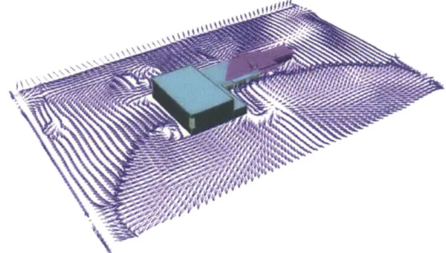
One case study I researched is entitled "Is day natural ventilation still possible in office buildings with a double-skin faeade?" by Gratia and De Herde is a study in which natural ventilation was simulated to greatly reduce energy use and energy costs in a Belgian office building. The study's main focus was to test the effects of the double-skin faeade on natural ventilation. However, they also did standalone simulations of the office without the double-skin. I focused on these simulations in order to avoid potentially misleading data. The building studied was a middle-size office building with 150 office modules aligned on two facades distributed over five floors separated
by a central corridor (see Figure 1038).
67 m
ii.
I 1111
1111
UE
_ _ _ _ _ _ _ _ _ _ _ _
Daftleldd faft-.J 54.5 M S
Figure 10: Gratia and de Herde office building
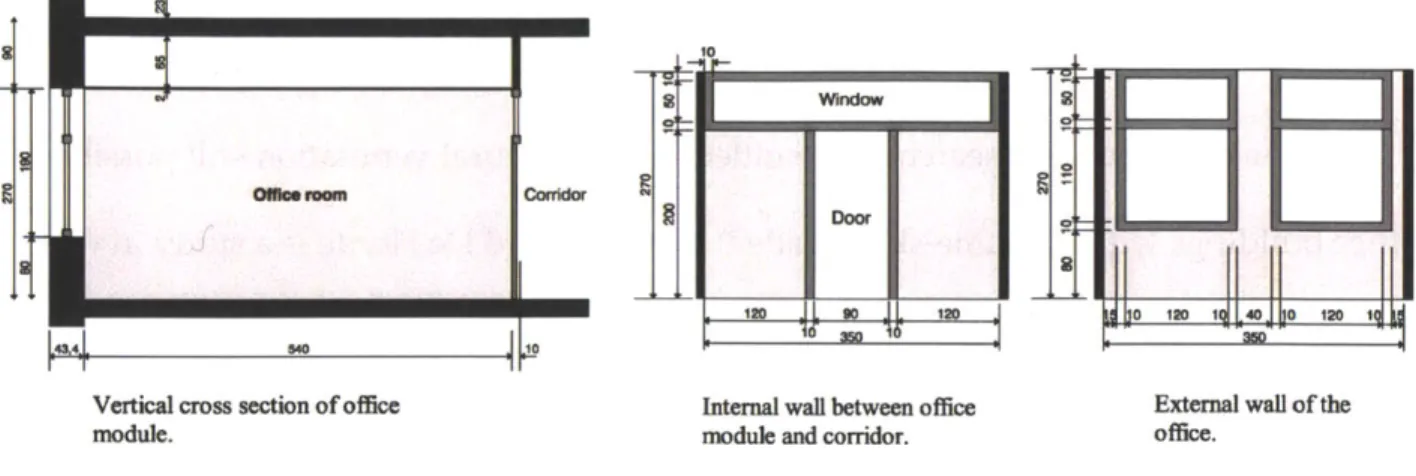
The internal walls between the office modules and the corridor have operable windows above the door to allow the flow of air between the northern and southern spaces. Each individual office module has four windows, two upper and two lower, in order to allow natural ventilation (see Figure 1138).
t
Oserown
Conidor R Door
i 120 I bo IV IL 1_R o 12o
Vertical cross section of office Internal wall between office External wall of the
module. module and corridor. office.
Figure 11: Vertical cross section of office module
The study utilized the Thermal Analysis Simulation (TAS) software package to generate the simulations that were analyzed in the study. TAS is a software package designed specifically for the thermal analysis of buildings. The TAS package contains a three-dimensional (3D) modeler, a thermal energy analysis module, a systems simulator, a two-dimensional computational fluid dynamics (2D CFD) package, and report generation facilities. The TAS program was designed to fully assess the thermal aspects of a building that can be used by designers to optimize a building's
environmental, energy, and comfort performance.39 These simulations were performed
using the climatic data of Uccle, Belgium and on July 24, a sunny summer day.38
The study's results were very supportive of the use of natural ventilation. The cooling load of the building without external shading devices and without natural ventilation was 1033 kilowatt hours (kWh) per day. When shading devices were added, the load reduced to 685 kWh per day. When both shading devices and natural ventilation during the day and night were utilized, the cooling load dramatically reduced. Introducing cross natural ventilation lowered the cooling load to 358 kWh per
day, while adding single-sided natural ventilation resulted in a cooling load of 252 kWh
per day.39
As the results above, natural ventilation is quite effective at reducing the cooling load on a building. In this study, the office building was able to see a simulated cooling load reduction of sixty-three percent simply by the addition of single-sided natural
ventilation.39 Gratia and De Herde also suggested methods as to increase the efficacy of
natural ventilation further, if, for example, their site saw reduced wind speeds. Two simple methods would be to increase the size of the window openings and to place
additional windows at various levels to encourage the stack effect.39
The next case study I have reviewed is one in which natural ventilation has the potential to vastly improve occupant health in health care facilities. This study is entitled "Natural Ventilation for the Prevention of Airborne Contagion." The transmission of drug-susceptible and drug-resistant tuberculosis (TB) is a major health issue in health care settings. A group of researchers from PLOS Medicine evaluated how natural ventilation affects air exchange rates and the estimated transmission risk of TB in hospitals in Lima, Peru."
In order to assess this, the group utilized a carbon dioxide decay technique to measure ventilation in air changes per hour (ACH). They also evaluated the room types to determine the factors that affect the ACH. They then used the Wells-Riley equation to estimate the transmission risk of TB.40 They evaluated seventy naturally ventilated rooms and twelve mechanically-ventilated rooms in eight hospitals during the study.
Five of these hospitals were built prior to 1950, whereas three of these hospitals were
more modem, having been built between 1970 and 1990. 4
The older rooms were mechanically ventilated with a constant ACH of twelve and an estimated TB transmission risk of 39% following a twenty-four exposure period to an infectious TB carrier. The modem, natural ventilated rooms were similar to the mechanically ventilated rooms in their basic design, but differed because they had open windows and doors. These rooms had an average ACH of seventeen, and an estimated TB transmission risk of 33%. The older, natural ventilated rooms were distinct in their design, having large windows and tall ceilings. Unsurprisingly, these rooms had the highest ACH among the selected group (forty), and an estimated TB transmission risk of 11%.4
Though we are not as concerned with TB in the United States as in other regions, it still remains a public health problem in many areas in the world. This study highlights the potential for prevention of infectious airborne diseases through the use of natural ventilation in health care settings. That is something that cannot be said for mechanical ventilation systems.
The next case study, "Assessing Building Performance in Use 4: The Probe Occupant Surveys and Their Implications," comes from Leaman and Bordass, faculty for the Usable Buildings Trust (UBT) in the United Kingdom. They conducted a series of surveys with the intent of linking occupants' indoor environments with their health,
natural ventilation, their research provides insight into how natural ventilation relates to occupant productivity and comfort, an often overlooked aspect of building design.
According to the study, the general rule is that the deeper a building gets, the lower the overall satisfaction and productivity of the occupants are. The optimal depth that they found is about 12m across the building.42 This is close to the limit of simple natural ventilation which is 15m across. If a building becomes deeper than this,
mechanical systems must be added to adequately ventilate the building.42 Therefore,
these researchers suggest that ventilation type and occupant comfort and productivity are closely linked. Though this detail represents a design limitation for natural ventilation, it also indicates that humans have a preference for buildings with natural ventilation as opposed to mechanical ventilation.
The study also states that occupants simply prefer natural ventilation over mechanical ventilation in the fall, winter, and spring seasons, but they prefer
mechanical air conditioning, unsurprisingly, in the summer.42 This would make sense,
considering how hot certain regions can get during the summer. However, I would like to cite my original case study when I say that perhaps we can change how people feel about natural ventilation in the summer. Though a stigma may exist that air conditioning is necessary in the summer, the study conducted by Gratia and De Herde would indicate that natural ventilation dramatically reduces the cooling load of a
In addition, better occupant health is also statistically associated with natural ventilation. As shown in the previous study by BMC, the transmission of airborne decisions is reduced by incorporating natural ventilation.4 Furthermore, Leaman and Bordass state that buildings which rely on mechanical ventilation systems have historically had more reports of ill-health, more specifically with chronic, building-related symptoms such as dry eyes and a stuffy nose than those with natural ventilation systems.4 This close linkage suggests that HVAC systems are almost certainly the cause of these building-related symptoms.
The research I have reviewed suggests that it is beneficial to consider natural ventilation as an alternative to mechanical ventilation. However, I feel it is a necessary component of research into energy efficiency. The urban environment is very rapidly approaching a state at which humans will no longer be able to sustain it. Soon enough, the price of the resources required for our cities to maintain themselves will become too great. However, natural ventilation provides a very promising solution to the majority of our cooling concerns. If we can utilize it as an alternative to mechanical ventilation, we can move towards become a more efficient, sustainable society.
The problem that most designers face with regards to natural ventilation is that they often cannot implement it. Architects are typically not trained in the building sciences, and therefore do not have knowledge of how natural ventilation systems work. This makes it very difficult for architects to incorporate natural ventilation into the early stages of their building design. At the point when a skilled engineer is able to
intervene in the architect's original design, it is too late for natural ventilation to be integrated into the design. This is due natural ventilation having so many design considerations that must be accommodated for. Additionally, mechanical ventilation and natural ventilation do not complement each other in design, exacerbating the issue.
5. METHODOLOGY
This chapter discusses my approach to the research problem outlined in Chapter
4, Literature Review - Naturally Ventilated Building Design. I conducted my research
in an iterative process, ensuring that my work can be followed and replicated by anybody who wishes to. As my research is intended to be used as a guide, this specification is critical to its success in that regard. Additionally, I approached this project from a designer's point of view, as if I were an architect with the intent of designing a sustainable building.
I began my thesis research with choosing a modeling program to work with.
Though this task may sound trivial, choosing the correct program was an essential part of ensuring proper simulations. The programs that I considered were CONTAM, CoolVent, EnergyPlus, and TRNSYS. Though all the programs can be used for simulating natural ventilation, they differ dramatically in their usage and capacity.
CONTAM, though a competent tool for running natural ventilation simulations,
does not have a very user-friendly interface. Due to how much time I would need to dedicate to simulations, I decided that my time would be better spent in simulations than in working with the CONTAM interface. CoolVent also did not make the cut, due to the limited geometry that it allows users. As I intended to work with custom geometry, CoolVent was simply not an option. And while EnergyPlus is a useful tool for whole building energy simulations, its natural ventilation component is a bit lacking as compared to other programs. TRNSYS combines the useful aspects of the other
programs with the additional benefit of allowing the user to have instant quantitative feedback on their simulations. This made TRNSYS the best choice for my thesis research. My detailed selection process is outlined in Chapter 6, Choosing a Modeling Program.
I then turned my research towards defining building typologies. I eventually
decided on two building typologies to each serve different purposes. These are 1) an office building based on the Department of Energy (DOE) Medium Office reference
building43 and 2) a residential building based on my fraternity (Sigma Alpha Epsilon or
SAE) house.
I chose my first typology for several reasons. The first was to dispel the notion that office buildings cannot be properly naturally ventilated. The details of this hypothetical building are also carefully
documented by the DOE, making
modeling this building in TRNSYS
relatively straightforward. This allowed
Figure 12 4: DOE Medium Office reference building me to produce very accurate simulations.
I chose to model my fraternity's
brownstone because I had access to all of the construction details I needed as a result of being a fraternity brother. Furthermore, I lived at the fraternity house during several summers of my undergraduate career, allowing me to compare simulation results to my own personal experience.
Additionally, as the SAE house is an existing building, I could then make distinctions between the research process for SAE and for the DOE reference building. As the DOE reference building
is not an existing building, different Figure 13: 165 Bay State Road
considerations needed to be taken into account. This distinction makes my research more comprehensive and applicable to my readers.
More details about my building type modeling process can be found in Chapter
The next step I took in my research was to learn how to utilize the TRNSYS programming environment. The detailed guide to using TRNSYS for building
simulations can be found in Chapter 7, Building Modeling in TRNSYS.
The next step was to create these models of my proposed building typologies in TRNBuild. TRNBuild is an interface within the TRNSYS environment used for creating and editing all of the non-geometry information required by TRNSYS for simulation."4 The detailed process for modeling building systems in TRNBuild can be found in Chapter 8, Building Editing in TRNBuild.
I initially modeled both building types as standard, mechanically ventilated
buildings in Boston. The next step was to introduce my new design interventions to the original models. This process was made possible through the use of TRNFlow, a component of the TRNBuild interface used for natural ventilation calculations. Because TRNFlow is fully integrated into the TRNBuild environment, it acts simply as an extension of an existing building project. This makes natural ventilation calculations relatively straightforward. TRNFlow will be discussed further in Secton 9, TRNFlow.
The next step in my project was to analyze the data I received in order to make informed decisions about my designs. Though TRNSYS is a great simulation tool, for the purposes of my thesis, it will only be used to supplement my design process, as opposed to being the primary form-giver. This will be discussed further in Chapter 11, Results.
6. CHOOSING A MODELING PROGRAM
One modeling program I considered was CONTAM. CONTAM is a multizone
indoor air quality and ventilation analysis program.45 The primary benefits of
CONTAM in the context of my research are the ability to calculate infiltration,
room-to-room airflows driven by mechanical ventilation, wind pressures, and buoyancy effects. Though it is a competent tool for calculating airflows, it does not have a very user-friendly interface. TRNFlow is also a better program for calculating effects from natural ventilation.
CoolVent is another program that I could have potentially used in my thesis research. CoolVent is an airflow network tool that uses energy and airflow calculations to model buoyancy-driven flow.4 CoolVent is used specifically for predicting the effects of natural ventilation on occupant comfort and energy savings. It is also aimed to be a simple program that can be used by architects, designers, and engineers in the early
design stages.47 This is pretty much exactly what I want to do. However, CoolVent is
too limited of a program for my research because you are restricted in the geometry that you can use. My project intends to allow the users of my methods to be very specific in their geometry.
EnergyPlus, unlike CoolVent or CONTAM, is a whole building energy simulation
program. It allows users to model energy performance and water use in buildings.4
1 It is
comfort, and natural ventilation are just some aspects of this program. However, the natural ventilation model is simply not as advanced as that of TRNFlow.
I eventually decided on using TRNSYS as my program. TRNSYS is a transient
systems simulation program.49 To name just a few use cases, TRNSYS is utilized to
simulate renewable energy, high performance buildings, and electric power generation. For the purposes of my thesis, I used TRNSYS as a tool for running various building energy simulations on my building models. The real advantage, however, was TRNFlow.
TRNFlow is a tool that allows a user to make ventilation-related calculations
within TRNBuild. By converting the mechanically ventilated models to naturally
ventilated models, I was then able to quantitatively compare results from my original simulations to my new simulations. This ability of TRNSYS to test and immediately receive feedback on the efficacy of model changes is a very useful aspect for designers.
7. BUILDING MODELING IN TRNSYS
Select project type
Empty TRNSYS New Solar hot
Project Compon... water system
Project ... Project (
COMIS project Coupled Empty COMIS
project project
step 1
Descrption
Mut-tizone biddin model The assistant wit help you set up a muLtizone beAdin project, indiding the buiing desciption, You can use the TRNSYS building editor (MR ild) afterwards to modify the bidin in t project window (@ght-dldc
Ion typeS6 and diose Edit a~dng.
LI~IZ
CancelFigure 14: New Building Project
Modeling a building in
TRNSYS starts with
acquiring the TRNSYS
software package from the
Pricing & Ordering
Chapter of the TRNSYS
website.5' The next step is
to open the Simulation Studio and start a new project. You will then want to create a new Building Project (multizone) as shown below. Take note that most parameters defined in the Simulation Studio can later be changed in TRNBuild. You
are also able to move
forward and backward
through the model assistant
to edit variables as you
please.
You are then asked to create a building floor plan
step 2
Left-cick on the plan to add / remove zones. This simpled iepresenta*iori is only used to define adnacencies between zones. It does not
necesa reflect he geometry of We biidogcorfectly , A 8 C 1 E F G N I J 2 3 4 5 6 7 81
<<Previous Step 2/10 Next
Figure 15: Building floorplan
Building fAoorplan Adjacency List
Cancel
to define zones and their adjacencies (see Figure 15). It is important to note that actual geometry will not be taken into account in this building model; you will have to keep a separate model if you desire one. This is highly preferred, so that you can relate the technical model to a more visual one in order to preserve the connection between your simulations and your architecture. Additionally, parameters defined in setting up your building project will apply to all zones, but each zone can be customized in TRNBuild after the fact.
You will then have to define your zone dimensions (not pictured). The helper will ask you to name each zone, as well as define its height, width, and depth in meters. This is when keeping keep a separate computer-aided design (CAD) model saved to use as a reference for your TRNSYS model can be very beneficial. It is also possible to add or edit zones and zone dimensions in TRNBuild, so there is no need to restart this whole process if you change your mind about your initial design.
The next step will ask you to define a few more parameters related to the building project (below). The first is the window to wall ratio (WWR) for each faeade of your building. The second is the building's rotation relative to the north axis. Then you will have to input a TRNSYS weather file to define the location of your building. Upon clicking the 'Browse' button, TRNSYS will direct you to your weather file directory in your TRNSYS folder. From there, you will be able to select a weather file from those that were downloaded during the TRNSYS installation. Additionally, you can also navigate to any weather file that you have downloaded on your computer, provided it
is a weather file readable by TRNSYS. TRNSYS can read weather files in the TMY, TMY2, TMY3, IWEC, CWEC, EPW, TM2, and TRY formats. This weather file can be altered in the Simulation Studio after your model is complete.
Windows, orientation and location
Fracwan of windws in extemal wa %] Ig rotation
Nrth West 0.0 0.0 East 0.0 South Rotatm Ollorib to East -poAive) 0 deg.]
Location .\Westher S-TMY2tUS-W-Madison-1437. trn2 Ews ee j
open
Y 3earch se.ther
Organize * New folder
& Recent places A Name Date modified TypE pCWEC 2 24214 q:55 PM Filefold
kDcunt p. Energy. 21242014 o:55 PM Fie fold
P. IWEC 2 24 20149:55 PM Fi2e fol
pPictures j Pubi JP-AMeDAS 2 24 2214 9:55 PM File fold p Meteonorm 224 2214 9:55 PM Fieffold U4
Homegroup ' US-TMY '19 2014 9:33 PM F1, fold!
US-TMY2 Z '214 13:22 PM Fiefld 01 This PC2421'nPrt
a ThiskpC. Weatherctenerator 2 24' 2214 255 PMA Pile foldi
I Documents Readme 10,2 2i-IC09 6:21 PM Trem DO File name: A ll Files(.1
<< Previous Step 4/10 Next >> Cancel Open Cancel
Figure 16: Windows, orientation and location
The next two steps refer to ventilation and air exchange within your building. The image below details the various parameters you are asked to provide for TRNSYS. You can specify the infiltration rate, mechanical and natural ventilation controls, and heating and cooling constraints. These values can be changed in TRNBuild after model completion. In addition, these parameters can be left blank and adjusted for individual
Infiltration and venti ation
Indtratin (valid for al zones)
Leakcage 0 2
W chand c vondaion
Vendaton rate (occupied) 0
Vendaton rate (unmoumed) 0
M Natural ventilation
Vntlallon rate
(-bcog 0
(0]
10' Humnkdty offpiyoar 50
[I] Supply twmpratre 20 1%]
[deg. Cl
AMd tem. dependent mnonan
Valionstart 24 1:
Venslon sap 23 [deg C)
Vendftn rate 3 (IA']
Radatve part of heating N
[Y
Set teperature day One [f [dig. C1
Set leaperaturenlgtlme j5t [dg. CJ Spedfiheatn power [1i (WIM^2]
9
Spe abn p- F
0 *
[W~m-21
Values apply toal ans.
They can be Cttin TRNMui later (a separate
heIt type is created tsr rach mme).
Valuesay to al amnvs.
Theycan be daso in
TRS dIate a piarate
-o& type aid be aested
fr sadc zane).
zones in TRNBuild.
You will then be prompted to define the internal
Internal gains
Specific gains 14 [W/mA2] Values apply to al zones.
They can be changed in
rvn~r t eft 0.1 rn +/M7 TRN~uid later.
Lighting
Light ON if total
horizontal rad < Light OFF if total horizontal rad > Specdfic light 120 '200 10 f'A^2] [WinA2] WV/MA2]
Values apply to a, zones. They can be changed in TRNBuildlater.
Previous Step 7/10 Next > Cancel
Figure 18: Gains and lighting
TRNSYS offers a lot of design specificity. This level of designers.
gains in your includes lighting as
space. This step
gains from
well.
TRNSYS also allows you
to define the shading
parameters for your
building. You can specify both fixed shading and
movable, or active,
shading. As you can see, detail is incredibly useful for
A
Orientation Acive + North + South + East -+ Weot RJActve WWidowheigh- 0.0 [m] 41 Wndow w lid Wngwal S S - 0.0 [m] el- 00 [ml s1- 00 d- 0.0 [m] e2- 0.0 [m] di- 0,0 al. 0.0 < Prevku Step 8/10Figure 19: Fixed and movable shading
Idlhb- 0.0 [m - S -[M] s2- 0.0 [m) [m] d2- 0.0 [m] [m] a2- o0o [m] M Onentaben Active *+North + South RAchmv
Coge f to~tW radation on facade > 140
open i tota radaion facade < 120
« ntiern 70
i<< Prevkxus step 9/10 r_
ovable shading [WiO^2] [W/m^2] [%] Cancel x > Fixed shading A I
The final dialog box in the assistant is simply for completing the process. At this point, you can return to any of the previous dialog boxes to edit your model, you can cancel the project entirely, or you can complete the project description. If you choose to complete the project, you will find yourself in the Simulation Studio environment as seen in Figure 20.
Pa. tda V- D. - A-1*4 CM*4Ar. 1~.f *.W
0 e
L..
* **0
-Figure 20: Simulation Studio
At this point, you have successfully created your first building project. The next chapter will detail how to use the TRNBuild editor to make more advanced changes to your building.
8. BUILDING EDITING IN TRNBUILD
In order to begin editing in TRNBuild, you must navigate to your building project in the TRNBuild editor. This can be accomplished in several ways. The first is to open your building project directly from the Simulation Studio. To do this, you have to right-click on your Building, and right-click the Edit Building option (see Figure 21).
Start Link
Edit connections with... Edit Building
Update building variable list Export to NBDM... Graphic Cut Copy Paste Delete Variables... Parameters... Inputs... Outputs... Derivatives... Proforma... Replace Add/Remove trace Lock/Unlock Send to layer Open in spreadsheet CtrI+X CtrI+C CtrIkV Del
The second way is to open your
building using the TRNBuild MFC
Application. You can access this by navigating to your TRNSYS directory on your computer, double-clicking on the Building folder, and double-clicking the
TRNBuild file. It should be easily
recognizable, as the file icon is the same as the Building icon featured above. It is also labeled as an Application file. Then, navigate to the File drop down menu and click Open. A pop-up window will appear and prompt you to select your building file. Note that these files are
E3 rq
Builditig
E a 0
TRNBuild Building File or .b17 files, which are different from the files you open in the Simulation Studio, which are TRNSYS Studio Project or .tpf files.
The final way is to navigate to your building project folder and to right-click your building file directly. Then click the Open with option and choose to open the file with your TRNBuild MFC Application.
After you have opened your building file, you will find yourself in the TRNBuild Navigator (see Figure 22).
JA~iAJii~1 A -A,.P 7*1 *K U
I
~ '%N f~o~Figure 22: TRNBuild Navigator
. OM
A I!U_ e :' db ! "
If you are looking at the above screen you can begin to edit your building. You may
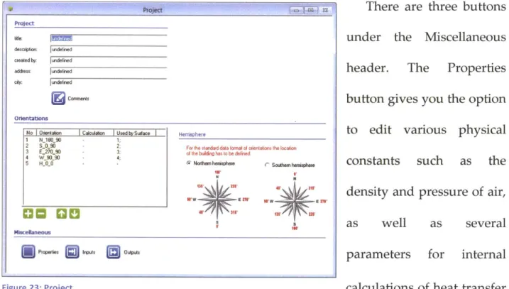
want to start with the project initialization window (see Figure 23).
This window allows you to edit some general information about your project. You can specify project title, description, creator, address, and city under the Project header. Under Orientations you can define how surfaces in your project are oriented. Under Hemisphere you can define the orientation of the building itself.
There are three buttons under the Niscellaneous
header. The Properties
button gives you the option to edit various physical
constants such as the
density and pressure of air,
as well as several
parameters for internal
Figure 23: Project calculations of heat transfer
coefficients. You will, in most cases, not be changing the TRNBuild-supplied values. Only experienced TRNSYS users should even consider changing the default values. The Inputs button displays the TRNBuild-supplied inputs to your project, as well as allows you to view and edit any user-defined inputs. Similarly, user-defined inputs should only be altered by advanced TRNSYS users. The Outputs button shows you the outputs
Project
We iffff
description undeined
cieated by: lundefied
address: Iudefined
city undelined
Orlentatons
No Orientalion COalan U IedbSuwace Hemisphere 1 N_18090 1;
2 S..O90 2: For the standard data orntrit 0 rnttons the location 3 E27O90 o e bil to be defned
4 W-91_90 4:
5 H 0 0 r Northenherimphue C Soum henrisphee
1W1 3 Miscelaneous -Properties Inputs
(
ulist, which will be an important aspect for designers. It allows you to specify all the various simulation outputs. Some examples are the temperature of an air node, the absolute humidity (humidity ratio) of an air node, and the sensible energy demand of an air node.
The next step is to become familiar with the Zone Window (below). This window can be accessed by clicking upon any of your zones in the TRNBuild Navigator. In order to add a new zone, you can click on the Zones drop-down menu and click Add Zone. Similarly, you can click on Delete Active Zone in this menu to delete a selected zone.
The Airnodes header indicates the airn zone. For the purposes of
Anodes AUnode
TRNBuild, an airnode is AINODE
defined as a single, ti-....
isolated volume of air. You can, if you choose, model
several airnodes in a single
ZRN
thermal zone in order to
view fac to.*0k 0.5
create multi-airnode zones. Modeling a double faqade
Figure 24: Zone - Airnode
or an atrium might
necessitate multi-airnode zones, for example.
:de regimes you have specified for each
Vrm Data
o^ -3 I.#=don Hoatein rine VA.*
0-C 12 MIA & C-% C---
,
oHti*. ThRa ThM Rzon
fWu4 iSyp. l IND ICtlm.wy I WVAR I d
IT
F rolye ~ undodn d <-ne - _ F a" 0 1 m-2
Caegw rE-TFNA
-oritabon I neie Elef %0
view fWc tosk *t. o
r ft mal Omd facoW I Al2 inm wdood
There are four different kinds of required regime data you must take into account in the Zone Window. These are volume, capacitance, initial zone temperature and relative humidity, and humidity model.
Volume simply refers to the volume of air within the airnode. TRNBuild will automatically calculate the capacitance for you at a value of 1.2*volume. You also have to enter the initial zone temperature and relative humidity. These will differ depending on the temperature of air supplied to your space. For most typical HVAC systems, these values are 20'C and 50% relatively humidity. As far as the humidity model is concerned, we can just utilize the simple humidity model that is the default for TRNBuild for most modeling purposes. A detailed moisture capacitance model is simply unnecessary for the vast majority of designs.
One important thing to note about the TRNBuild interface is that each component of your building project can be referred to as a type. Wall, Layer, Window, Infiltration, Ventilation, Schedule, etc. are all examples of types. Furthermore, each type has a type manager associated with it. Type managers are used for adding new types, deleting existing types, or editing properties of existing types. The four edit buttons found on the bottom-right corner of each type manager (see Figure 25) are used to rename, delete,
copy, and make new types, respectively. The remainder of this chapter
IMIN
I
I
will discuss the importance of these types in regards to your building Figure 25: RDCN
Wail
Surf i Type I iArea ICategory I
Additional Windows undefined F<-- new 0.1 m^2 incl. windows IEXTERNAL al0 1 0 10 kJ/h undefined FN_18O_90 10.5
In the lower left of
the Zone Window, users can add, edit, or delete a wall within an aimode. The upper window provides an overview of all defined walls. Below this window is the displayed definition
of the selected wall.
Clicking on a wall in the upper window allows the user to edit it. This window
Figure 26: Walls
gives you the ability to define every aspect of each individual wall construction. Do note that every wall in your building project must be defined in order to ensure an accurate simulation. This is where having a CAD model of your building project to work with alongside your TRNSYS model becomes very useful. The plus button adds new walls and the minus button is used to delete selected walls.
This same process can be repeated to create all the windows in your building project (next page). Similar to the walls, your window constructions should be specified for each window. To access your window menu, click on any wall in your building
wall type: area: category: geosurf: wal gain: orientation: view fac. to sky:
project. You will then be able to define any windows within that specific wall construction.
The zone window
also allows you to define any optional data such as infiltration, heating, gains,
ventilation, cooling, and
comfort. If you choose not to define any of this data
yourself, TRNBuild will
automatically use the data you filled in during the building creation process in
Chapter 7, Building
Modeling in TRNSYS.
(eWmdows
Surf I Type IArea I Category Iu-Value I g-Value
window type: area: category: geosurf: gain: orientation: view fac. to sky:
F internal shad. factor:
- external shad. factor .hAdng corool, undefined
J
~.~ IEXTERNAL010
IF2
al0 kJ/h undefined N 390 10.5S itred rdic ni aCLdF c A o w1ind yp ( Iri- c rA i -Idr d n I d
Figure 27: Windows
Therefore, it is advised to go through and specify each for every zone.
The Infiltration type (see Figure 28) can be used to specify an air flow from the outside of the zone into the zone. Infiltration is generally based off of wall construction.
Fundamentals Handbook or DOE Commercial Reference Buildings. Then click new to define an infiltration for your zone and the check button to confirm your selection.
Infiltration [ AirNode: AIRNODE ]I Infiltration
C off r. on Infiltration Type
undefined <- new.
Figure 28: Infiltration
New Infiftratio Type
' Infliltration Type" Manager
new infiltration type: Airchange of Infiltration
0 10.6 1/h
Figure 29: New Infiltration Type
Ventilation in TRNBuild is defined as air flow into the airnode from heating or cooling equipment. Ventilation is an optional setting and TRNBuild defaults it to off. However, when considering the viability of natural ventilation as opposed to mechanical ventilation, it is useful to turn ventilation on. To turn ventilation on, click on
the Ventilation button in the Airnode
Ventilation[ AirNode: AIRNODE]
Window (see Figure 30). You can use this
Ventilation
dialog box to select, add, or delete ventilation types.
Upon clicking new, you will find yourself in the Ventilation Type Manager (see Figure 31). Here, you can specify the
und
+:|
Ventilation Type efined
details for a new ventilation type. You have to establish the air change rate, temperature, and humidity of the air flow. These specifications should be easily accessible by anybody considering external ventilation systems in their building projects.
New Ventilation Type
-Ventiiation Type- Manager
new ventilation type: IVENTOOl AirFlow
T irn change rate Flow
mass flow rate Temperature of Air Flow
1/h
H outside
r- other 0 1j20 *
Humnidity of Air Flow relative humidity absolute humridity
(outside
(~other S130
Figure 31: New Ventilation Type
humidification if applicable. Selecting the unlimited option under Heating Power will cause TRNBuild to use as much heating power as necessary to maintain your setpoint temperature. The limited option will only apply as much heating power as is specified. The choice of which
r
The Heating button allows you to modify heating control for an airnode. Similar to
the Ventilation Type Manager, the
Heating Type Manager (see Figure 32) allows you to create, edit, or delete heating types. For heating types, you
must specify a room setpoint
temperature, the heating power, and air
New Heating Type "Heating Type" Manager
new heating type: JHEATOO
Room Temperature Control
set temperatue: 0 120 Heating Power r unlimited r- Wlied 11 radiative part: 10 Humidification r off (won r* relative humidity C lC U /1h %/100J absolute humidity I.
option to use depends entirely on your heating system
The Cooling Manager (see Figure 33) functions almost identically to the Heating
Manager. The particular values you need New Cooling Type
to use should also be specified by your Cookng Type" Manager
new cooling type: COOL001
Room Terperature Control set temperatue:
0
26 Internal gains can be defined byCooling Power
clicking the Gains button in the Zone r mwied
r- Wed all Wd h
Window. The Gains dialog box has very
Dehumidification
specific, predefined gain options that you r off
on
can select from each menu. For people r'''eh'm *"' "'"ut
01100 and computers, the scale refers to the
number of people or computers. For Figure 33: New Cooling Type
artificial lighting gains, the type of lamp, related floor area, and convective part must be
Gains [-AirNode: AIRNeE fined. Persons can also
UPerm=n
be added with varying
-- gm oepowFf
ct levels of activity. All these
ronwale 9OPF0 types of gains can, and
ACkif r*rWW
W _ _ MWt*wnshould often, be set on a
0 0schedule
according to the
Othesr Gains
Tw Scale Go~o n
operating hours of your
building project. For design Figure34: - G 4<-6
purposes, setting a schedule will be important, as each building generally
has its own type of
occupancy schedule. This will change from project to
project based on the
program and usage of the buildings.
Users can also add
Rates of Heat Gain from Occupants of Conditioned Spaces -ISO 7730
Rates of Heat Gain from Occupants of Cond
Total Heat Sensible Latent
Adjusted Heat Heat
No, Degree of Activity Typical Applicaton Watt Btu/h Watt Btu/h Watt Btu/h
r. 01 Seated at rest Theatre, Movie 100 350 60 210 40 140
C 02 Se _vight writing OficeHotelsApts 120 420 65 230 55 190
C 03 Seated, eatig RestaUant 170 580 75 255 95 325 " 04 Seated, fiht work, tying Office Hotel, Apts 150 510 75 255 75 255
C 05 Standing,fight work or Retail Store, Bank 185 640 90 315 95 325
working slowly
* 06 lightbenchwork Factory 230 780 100 345 130 435
C 07 walking 1,3m/s (3 mph) Factory 305 1040 100 345 205 695
light machine work
C 08 Bowling BowlingAlley 280 960 100 345 180 615
C os moderate dancing Dance Hall 375 1280 120 405 255 875
C 10 Heavywork,lifting Factory 470 1600 165 565 300 1035
Heavy machine work
C 1i Heavy work, athletics Gymnasium 525 1800 185 635 340 1165
Figure 35: Rates of Heat Gain from Occupants of Conditioned Spaces - ISO 7730
gains in addition to these predefined gains. A new gain type can be added by clicking new under Other Gains. This will direct you to the Gain Type Manager (see Figure 36). You must specify the radiative and convective power as well as the absolute humidity of the gain. Any new gain type definitions can also be saved for future modeling purposes.
Comfort is an optional setting for Users can use the Comfort dialog box (see Figure 36: New Gain Type
TRNBuild and its default is to be set off.
New Gain Type
"Gain Type" Manager
new gain type: Radiative Power
Convective Power
1 50 kJ/hr
Abs. Humidity
a10 kg/hr